Table of Contents
Advertisement
Comfort Systems
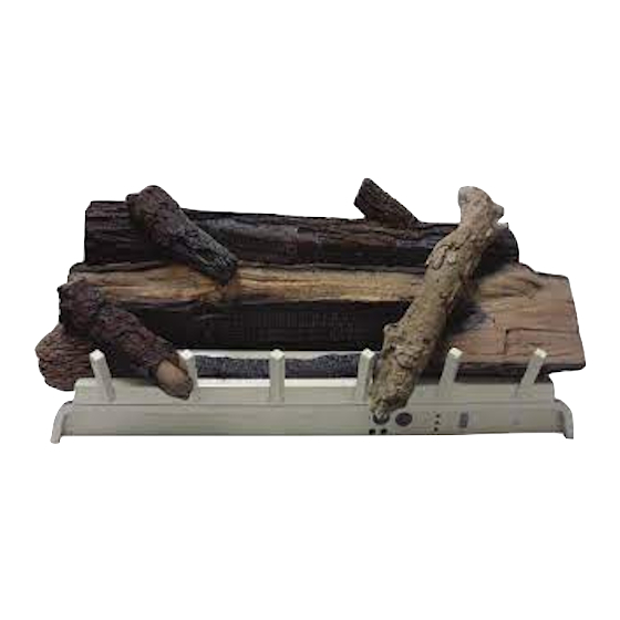
Vented/Vent-Free Burner and Logs
REFRACTORY LOGS
WARNING: If the information in this manual are
— WHAT TO DO IF YOU SMELL GAS
INSTALLATION INSTRUCTIONS
AND OWNER'S MANUAL
-
UNVENTED GAS LOG HEATER
MODELS
VFDR18LBW10N-4
VFDR18LBWN-3
VFDR24LBWN-3
VFDR30LBWN-3
VFDT18LBWN-3
VFDT24LBWN-3
VFDT30LBWN-3
VFDM18LBWN-3
VFDM24LBWN-3
VFDM30LBWN-3
VENTED DECORATIVE APPLIANCE
MODELS
VFDR18LBW10N-4
VFDR18LBWN-3
VFDR24LBWN-3
VFDR30LBWN-3
VFDM18LBWN-3
VFDM24LBWN-3
VFDM30LBWN-3
for adequate combustion and ventilation air must be
WARNING: If not installed, operated and maintained
in accordance with the manufacturer's instructions,
or from fuel combustion which can cause death or
WATER VAPOR: A BY-PRODUCT OF UN-VENTED
ROOM HEATERS
VFDR18LBW10P-4
VFDR18LBWP-3
VFDR24LBWP-3
VFDR30LBWP-3
VFDT18LBWP-3
VFDT24LBWP-3
VFDT30LBWP-3
VFDM18LBWP-3
VFDM24LBWP-3
VFDM30LBWP-3
VFDR18LBW10P-4
VFDR18LBWP-3
VFDR24LBWP-3
VFDR30LBWP-3
VFDM18LBWP-3
VFDM24LBWP-3
VFDM30LBWP-3
-
Page 1
Advertisement
Table of Contents

Related Manuals for Empire Comfort Systems VFDR18LBW10N-4


Summary of Contents for Empire Comfort Systems VFDR18LBW10N-4
- Page 1 INSTALLATION INSTRUCTIONS AND OWNER'S MANUAL Comfort Systems Vented/Vent-Free Burner and Logs UNVENTED GAS LOG HEATER MODELS VFDR18LBW10N-4 VFDR18LBW10P-4 VFDR18LBWN-3 VFDR18LBWP-3 VFDR24LBWN-3 VFDR24LBWP-3 VFDR30LBWN-3 VFDR30LBWP-3 VFDT18LBWN-3 VFDT18LBWP-3 VFDT24LBWN-3 VFDT24LBWP-3 VFDT30LBWN-3 VFDT30LBWP-3 VFDM18LBWN-3 VFDM18LBWP-3 REFRACTORY LOGS VFDM24LBWN-3 VFDM24LBWP-3 VFDM30LBWN-3 VFDM30LBWP-3 VENTED DECORATIVE APPLIANCE...
-
Page 2: Table Of Contents
TABLE OF CONTENTS SECTION PAGE IMPORTANT SAFETY INFORMATION..............3 SAFETY INFORMATION FOR USERS OF LP-GAS ..........4 INTRODUCTION......................5 PRODUCT SPECIFICATIONS.................6 WATER VAPOR: A BY-PRODUCT OF UNVENTED ROOM HEATERS ....6 GENERAL INFORMATION ..................7 REQUIREMENTS FOR CANADA................8 PROVISIONS FOR ADEQUATE COMBUSTION & VENTILATION AIR ....9 CLEARANCES....................9-10 COMBUSTIBLE MATERIAL................... -
Page 3: Important Safety Information
IMPORTANT SAFETY INFORMATION DANGER: Indicates a hazardous situation which, if not avoided, will result in death or serious injury. WARNING: Indicates a hazardous situation which, if not avoided, could result in death or serious injury. NOTICE CAUTION: Indicates a hazardous situation which, if not avoided, could result in minor or moderate injury. -
Page 4: Safety Information For Users Of Lp-Gas
SAFETY INFORMATION FOR USERS OF LP-GAS LP-GAS WARNING ODOR phone. Do not do anything that could ignite the gas. not continue to smell gas, do not turn on the gas again. Do that IMMEDIATELY. Do not re-enter the building, vehicle, trailer, or area. caped gas. -
Page 5: Introduction
INTRODUCTION smoke will occur. To prevent triggering of smoke alarms, ventilate the room in which the unit is installed. WARNING Please read this manual before installing and using the Instructions to Installer 1. Installer must leave instruction manual with owner after installation. -
Page 6: Product Specifications
PRODUCT SPECIFICATIONS Regulator Pressure Gas Inlet Pressure Gas Inlet Pressure Model Setting Minimum Natural 3.5" W.C. 10.5" W.C. 4.5" W.C. VFDR(18,24,30)LBW Millivolt Propane 10.0" W.C. 13.0" W.C. 11.0" W.C. Natural 3.5" W.C. 10.5" W.C. 5.0" W.C. VFDR18LBW10 Millivolt Propane 10.0" W.C. 13.0"... -
Page 7: General Information
GENERAL INFORMATION and ventilation air must be provided. Keep room area clear and free from combustible materials, gasoline person or through a representative is engaged in and is responsible for (a) the installation, testing, or replacement of gas piping or (b) the Unvented gas heaters are a supplemental zone heater. -
Page 8: Requirements For Canada
REQUIREMENTS FOR CANADA This unit cannot be installed in a UNVENTED application, this or near the appliance. unit be installed as a VENTED application with these eration. IMPORTANT SAFETY INFORMATION bonding agents. These bonding agents are not harmful but This unit complies with ANSI Z21.60and CGA 2.26 Decorative may produce annoying smoke and smells as they are burned Gas Appliances For Installation In Solid Fuel Burning Fireplaces. -
Page 9: Provisions For Adequate Combustion & Ventilation Air
PROVISIONS FOR ADEQUATE COMBUSTION & VENTILATION AIR Btuh of the combined input rates of all appliances drawing combustion areas outside the space must draw return air from outside the space through the space for combustion air. One opening must be within 12 inches of the sizing of these openings is determined by whether inside or outside air is used to support combustion, the method by which the air is brought to the space (vertical or horizontal duct) and by the total input rate of all appli-... - Page 10 Non-Combustible Requirements for Safe Installation Sidewall & Ceiling Clearances Material Distance 12" or more Non-combustible material Less than 12" Non-combustible material must be extended to at least 8" with the installa- cannot extend non-combustible material at least 8", you must operate heater with Mantel Clearances with Hood opening.
-
Page 11: Combustible Material
COMBUSTIBLE MATERIAL No greeting card, stockings or ornamentation of any type should be Figure 8 FIREPLACE PREPARATION FOR MASONRY BUILT FIREPLACES FREE OPENING AREA OF CHIMNEY DAMPER FOR VENTING remove ashes, soot, creosote or other obstructions. COMBUSTION PRODUCTS FROM DECORATIVE APPLIANCES Have this cleaning performed annually after installation. -
Page 12: Installing As A Vented Appliance
INSTALLING AS A VENTED APPLIANCE When installing your log set as a vent-free installation the damper clamp can be used to eliminate the potential for odors when burning When installing your log set as a vented installation the damper clamp must be used. Installing Damper Clamp cement or high temperature silicone. -
Page 13: Gas Supply
GAS SUPPLY Recommended Gas Pipe Diameter Pipe Length Schedule 40 Pipe Tubing, Type L Inside Diameter Outside Diameter Nat. L.P. Nat. L.P. 0-10 feet 1/2” 3/8” 1/2” 3/8” 0-3 meters 12.7mm 9.5mm 12.7mm 9.5mm 10-40 feet 1/2” 1/2” 5/8” 1/2” 4-12 meters 12.7mm 12.7mm... -
Page 14: Log Identification
LOG IDENTIFICATION Page 14 30726-0-0612... -
Page 15: Vfd(R,T,M)(18,24,30) & Vfdr18Lbw10 Log Placement
Before you begin: if you are installing logs onto the VFD(R,T,M)18 or EMBER MATERIAL PLACEMENT ON BURNER VFD(R,T,M)24 models, this burner assembly is supplied with a set After all logs are positioned properly, apply Rockwool ember material to the front burner port area. To apply, carefully separate the ember hands! Always wear gloves to prevent skin irritation from ceramic material into small amounts no larger than "dime size"... - Page 16 Place Rear Log (A) on rear log support. Align notch on bottom left of log with the rear burner support bracket. TOP VIEW FRONT VIEW Page 16 30726-0-0612...
- Page 17 Place Middle Log (B) in the center of the burner tube. Align notch on log with back of the far left burner support bracket. TOP VIEW FRONT VIEW 30726-0-0612 Page 17...
- Page 18 port bracket. TOP VIEW FRONT VIEW Page 18 30726-0-0612...
- Page 19 TOP VIEW FRONT VIEW 30726-0-0612 Page 19...
- Page 20 Place Top Left Log (E) in groove on Front Left Log (D) and rest on grate bar. TOP VIEW FRONT VIEW Page 20 30726-0-0612...
- Page 21 Place Top Right Log (F) in grooves between Middle Log (B) and Right Front Log (C). TOP VIEW FRONT VIEW 30726-0-0612 Page 21...
- Page 22 Place Top Middle Log (G) in grooves on Rear Log (A) and Middle Log (B). TOP VIEW FRONT VIEW Page 22 30726-0-0612...
-
Page 23: Operation Instructions/Flame Appearance
OPERATION INSTRUCTIONS/FLAME APPEARANCE Flames from the pilot (rear right back side of the pan burner) as is installed. NOTICE: up and down. patterns. Sooting and improper burning will result. During manufacturing, fabricating and shipping, various components These chemicals are not harmful, but may produce annoying smoke and smells as they are burned off during the initial operation of the appliance, possibly causing headaches or eye or lung irritation. -
Page 24: Wiring - Vfdr Models Only
WIRING - VFDR MODELS ONLY Thermostats are not approved on vented decorative appliances. behind bottom louver. Label all wires prior to disconnection when servicing controls. Wiring Refer to remote control installation and operating instructions for errors can cause improper and dangerous operation. Verify proper more details on remote control. -
Page 25: Vfdr(18,24,30)Lbw Lighting Instructions
FOR YOUR SAFETY READ BEFORE LIGHTING WARNING: WHAT TO DO IF YOU SMELL GAS LIGHTING INSTRUCTIONS STOP! Read the safety information above on this page. Turn gas control knob counterclockwise to "PILOT". Open bottom louver assembly (if applicable). Push in control knob all the way and hold in. Repeatedly push Set REMOTE/OFF/ON switch to the Piezo Ignitor Button until the pilot is lit. -
Page 26: Vfdr18Lbw10(N,P) Lighting Instructions
FOR YOUR SAFETY READ BEFORE LIGHTING WARNING: WHAT TO DO IF YOU SMELL GAS LIGHTING INSTRUCTIONS STOP! Read the safety information above on this page. Turn gas control knob counterclockwise to "PILOT". Open bottom louver assembly (if applicable). Push in control knob all the way and hold in. Repeatedly push Set REMOTE/OFF/ON switch to the Piezo Ignitor Button until the pilot is lit. -
Page 27: Vfdt(18,24,30)Lbw Lighting Instructions
FOR YOUR SAFETY READ BEFORE LIGHTING WARNING: WHAT TO DO IF YOU SMELL GAS LIGHTING INSTRUCTIONS STOP! Read the safety information above on this page. will pop back up. Pilot should remain lit. If it goes out, repeat steps 4 though 8. Set thermostat (gas control knob) to lowest setting. -
Page 28: Vfdm(18,24,30)Lbw Lighting Instructions
FOR YOUR SAFETY READ BEFORE LIGHTING WARNING: WHAT TO DO IF YOU SMELL GAS LIGHTING INSTRUCTIONS STOP! Read the safety information above on this page. lit. Release knob and it will pop back up. Pilot should remain lit. If it goes out, repeat steps 2 through 6. Push in gas control knob slightly and turn clockwise to "OFF."... -
Page 29: Pilot Flame Characteristics
PILOT FLAME CHARACTERISTICS cause the thermocouple to cool. When the thermocouple cools, the heater will shut down. Incorrect Pilot Flame Pattern for VFDR Figure 21 Correct Pilot Flame Pattern for VFDR Incorrect Flame Pattern for VFDT & VFDM Figure 22 Correct Pilot Flame Pattern for VFDT &... -
Page 30: Cleaning And Servicing
PILOT FLAME CHARACTERISTICS Cleaning and Maintenance/Pilot Depletion Sensor as follows: 1. Clean the ODS pilot by loosening nut B from the pilot tubing. wrench. 2. Blow air pressure through the holes indicated by the arrows. This will blow out foreign materials such as dust, lint and spider webs. -
Page 31: Troubleshooting
TROUBLESHOOTING SYMPTOMS, POSSIBLE CAUSES AND CORRECTIONS a. Ignitor electrode positioned wrong - Replace pilot. problem could be caused by either low gas pressure or dirty or b. Ignitor electrode is broken - Replace pilot. partially clogged ODS/pilot - Contact local gas company. c. -
Page 32: Vfdr Series Parts List
VFDR SERIES PARTS LIST Attention: When ordering parts, it is very important that part number and description of part coincide. PART NUMBERS DESCRIPTION VFDR18LBW VFDR24LBW VFDR30LBW 21588 21588 21588 PILOT SHIELD (NAT ONLY) R3623 R3623 R3623 PILOT ASSEMBLY (LPG) R3624 R3624 R3624 PILOT ASSEMBLY (NAT) -
Page 33: Vfdr Series Parts View
VFDR SERIES PARTS VIEW 18” BURNER 24” BURNER 7 PIECE LOG SET 30” BURNER 30726-0-0612 Page 33... -
Page 34: Vfdr18Lbw10 Parts List
VFDR18LBW10 PARTS LIST Attention: When ordering parts, it is very important that part number and description of part coincide. DESCRIPTION 21588 PILOT SHIELD (NAT ONLY) R3623 PILOT ASSEMBLY (LPG) R3624 PILOT ASSEMBLY (NAT) 21590 PILOT BRACKET (LPG) 23106 PILOT BRACKET (NAT) 27426 BURNER, TUBE 21592... -
Page 35: Vfdr18Lbw10 Parts View
VFDR18LBW10 PARTS VIEW 18” BURNER 7 PIECE LOG SET 30726-0-0612 Page 35... -
Page 36: Vfdt Series Parts List
VFDT SERIES PARTS LIST Attention: When ordering parts, it is very important that part number and description of part coincide. PARTS NUMBER DESCRIPTION VFDT18LBW VFDT24LBW VFDT30LBW 21588 21588 23157 PILOT SHIELD (NAT ONLY) R5170 R5170 R5170 PILOT ASSEMBLY (LPG) R5171 R5171 R5171 PILOT ASSEMBLY (NAT) -
Page 37: Vfdt Series Parts View
VFDT SERIES PARTS VIEW 18” BURNER 24” BURNER 7 PIECE LOG SET 30” BURNER 30726-0-0612 Page 37... -
Page 38: Vfdm Series Parts List
VFDM SERIES PARTS LIST Attention: When ordering parts, it is very important that part number and description of part coincide. PART NUMBER DESCRIPTION NUMBER VFDM18LB VFDM24LB VFDM30LB 21588 21588 23157 PILOT SHIELD (NAT ONLY) R5170 R5170 R5170 PILOT ASSEMBLY (LPG) R5171 R5171 R5171... -
Page 39: Vfdm Series Parts View
VFDM SERIES PARTS VIEW 18” BURNER 24” BURNER 7 PIECE LOG SET 30” BURNER 30726-0-0612 Page 39... -
Page 40: Master Parts Distributor List
To Order Parts After the Warranty Period, please contact your dealer or one of the Master Parts Distributors listed below. This list changes from time to time. For the current list, please click on the Master Parts button at www.empirecomfort.com. ment repair parts for Heaters, Grills, and Fireplaces manufactured by Empire Comfort Systems Inc. 1401 Willow Lake Boulevard... -
Page 41: Appliance Service History
APPLIANCE SERVICE HISTORY Date Dealer Name Service Technician Name Service Performed/Notes 30726-0-0612 Page 41... - Page 42 APPLIANCE SERVICE HISTORY Date Dealer Name Service Technician Name Service Performed/Notes Page 42 30726-0-0612...
- Page 43 APPLIANCE SERVICE HISTORY Date Dealer Name Service Technician Name Service Performed/Notes 30726-0-0612 Page 43...
- Page 44 Empire Comfort Systems Inc. 918 Freeburg Ave. Belleville, IL 62220 info@empirecomfort.com. Comfort Systems Page 44 30726-0-0612...
Need help?
Do you have a question about the VFDR18LBW10N-4 and is the answer not in the manual?
Questions and answers