Table of Contents
Advertisement
EMPIRE
EMPIRE
Comfort Systems
Vented/Vent-Free Loft Burner
Installer:
Leave this manual with the appliance.
Consumer: Retain this manual for future reference.
This appliance may be installed in an aftermarket
permanently located, manufactured (mobile)
home, where not prohibited by local codes.
This appliance is only for use with the type of gas
indicated on the rating plate. This appliance is not
convertible for use with other gases.
wArNING: If the information in this manual are
not followed exactly, a fire or explosion may re-
sult causing property damage, personal injury
or loss of life.
— Do not store or use gasoline or other flam-
mable vapors and liquids in the vicinity of
this or any other appliance.
— wHAT TO DO IF yOu SMeLL GAS
•
Do not try to light any appliance.
•
Do not touch any electrical switch; do not
use any phone in your building.
•
Immediately call your gas supplier from
a neighbor's phone. Follow the gas sup-
plier's instructions.
•
If you cannot reach your gas supplier, call
the fire department.
— Installation and service must be performed
by a qualified installer, service agency or the
gas supplier.
INSTALLATION INSTrucTIONS
AND OwNer'S MANuAL
uNVeNTeD GAS HeATer
MODeLS
VFrL1810(N,P)-1
VFrL(18,24,30)(N,P)-1
VFIL(18,24,30)(N,P)-1
VeNTeD DecOrATIVe APPLIANce
MODeLS
VFrL1810(N,P)-1
VFrL(18,24,30)(N,P)-1
GAS-FIRED
This is an unvented gas-fired heater. It uses air
(oxygen) from the room in which it is installed.
Provisions for adequate combustion and ventila-
tion air must be provided. Refer to page 11.
wArNING: If not installed, operated and main-
tained in accordance with the manufacturer's
instructions, this product could expose you to
substances in fuel or from fuel combustion which
can cause death or serious illness.
wATer VAPOr: A By-PrODucT OF uNVeNTeD
rOOM HeATerS
Water vapor is a by-product of gas combustion.
An unvented room heater produces approximately
one (1) ounce (30ml) of water for every 1,000 BTu's
(.3KW's) of gas input per hour. Refer to page 8.
Page 1
Advertisement
Table of Contents

Related Manuals for Empire Comfort Systems VFRL1810 Series


Summary of Contents for Empire Comfort Systems VFRL1810 Series
- Page 1 INSTALLATION INSTrucTIONS EMPIRE EMPIRE AND OwNer'S MANuAL Comfort Systems Vented/Vent-Free Loft Burner uNVeNTeD GAS HeATer MODeLS VFrL1810(N,P)-1 VFrL(18,24,30)(N,P)-1 VFIL(18,24,30)(N,P)-1 VeNTeD DecOrATIVe APPLIANce MODeLS VFrL1810(N,P)-1 VFrL(18,24,30)(N,P)-1 GAS-FIRED Installer: Leave this manual with the appliance. Consumer: Retain this manual for future reference. This appliance may be installed in an aftermarket permanently located, manufactured (mobile) home, where not prohibited by local codes.
-
Page 2: Table Of Contents
TABLe OF cONTeNTS SecTION PAGe Quick Start Guide ..........................3 Important Safety Information ......................5 Safety Information for Users of LP-Gas..................... 6 Introduction ............................7 Product Specifications ........................8 Water Vapor: A By-Product of Unvented Room Heaters ..............8 General Information ........................... 9 Requirements for Canada ....................... -
Page 3: Quick Start Guide
Quick Start Guide To STArT the Fireplace: If the pilot is NOT lit: 1. At the same time, press the “OFF” and high flame buttons and release once there is an audible “beep” sound. 2. The pilot will ignite on the sixth beep. You may hear a clicking sound around the same time as that beep, this is normal. - Page 4 THIS PAGE INTENTIONALLY LEFT BLANK Page 4 26532-5-0311...
-
Page 5: Important Safety Information
IMPOrTANT SAFeTy INFOrMATION • An unvented room heater having an input rating of more than • NOTE: Installation and repair should be done by a qualified 6,000 Btu per hour shall not be installed in a bathroom service person. The appliance should be inspected before •... -
Page 6: Safety Information For Users Of Lp-Gas
SAFeTy INFOrMATION FOr uSerS OF LP-GAS Propane (LP-Gas) is a flammable gas which can cause fires with the members of your household. Someday when there and explosions. In its natural state, propane is odorless and may not be a minute to lose, everyone's safety will depend colorless. -
Page 7: Introduction
INTrODucTION Notice: During initial firing of this unit, its paint will bake out, and IMPOrTANT: read all instructions carefully before starting smoke will occur. To prevent triggering of smoke alarms, ventilate installation. Failure to follow these installation instructions may the room in which the unit is installed. result in a possible fire hazard and will void the warranty. -
Page 8: Product Specifications
PrODucT SPecIFIcATIONS regulator Pressure Gas Inlet Pressure Gas Inlet Pressure Model Valve Type Setting Minimum Natural 3.5" W.C. 10.5" W.C. 4.5" W.C. VFRL(18,24,30) Millivolt Propane 10.0" W.C. 13.0" W.C. 11.0" W.C. Natural 3.5" W.C. 10.5" W.C. 45.0" W.C. VFRL1810 Millivolt Propane 10.0"... -
Page 9: General Information
GeNerAL INFOrMATION This is an unvented gas-fired heater. It uses air (oxygen) Qualified Installing Agency from the room in which it is installed. Provisions for adequate Installation and replacement of gas piping, gas utilization combustion and ventilation air must be provided. equipment or accessories and repair and servicing of equip- ment shall be performed only by a qualified agency. -
Page 10: Requirements For Canada
reQuIreMeNTS FOr cANADA This unit cannot be installed in a UNVENTED application, WARNING; DO NOT OPERATE THIS GAS APPLIANCE this unit can only be installed as a VENTED application wITH GLASS DOOrS cLOSeD with these requirements. • Clothing or other flammable material should not be IMPOrTANT SAFeTy INFOrMATION placed on or near the appliance. -
Page 11: Provisions For Adequate Combustion & Ventilation Air
PrOVISIONS FOr ADeQuATe cOMBuSTION & VeNTILATION AIr This heater shall not be installed in a confined space unless provi- sions are provided for adequate combustion and ventilation air. A confined space is an area with volume less than 50 cubic feet per 1,000 Btuh of the combined input rates of all appliances drawing combustion air from that space. -
Page 12: Clearances
cLeArANceS and 30" gas appliances) from the fireplace opening. Minimum Dimensions For Solid Fuel Burning Fireplaces UL127 Factory Built Fireplaces (Figure 2) Mantel clearances without Hood (Figure 4) You must have non-combustible materials above the fireplace Model or firebox opening. Non-combustible material must extend at VF(R,I)L1810 21"... -
Page 13: Combustible Material
cLeArANceS (continued) Mantel clearances with Hood (Figure 5) If your installation does not meet the above minimum clear- You must have non-combustible materials above the fireplace ances, you must proceed to one of the following steps: opening. Non-combustible material must extend at least 8" •... -
Page 14: Fireplace Preparation
FIrePLAce PrePArATION • Turn off gas supply to fireplace or firebox. FOr MASONry BuILT FIrePLAceS • Have the fireplace floor and chimney professionally cleaned to Free OPeNING AreA OF cHIMNey DAMPer FOr VeNTING cOMBuSTION PrODucTS FrOM DecOrATIVe APPLIANceS remove ashes, soot, creosote or other obstructions. FOr INSTALLATION IN SOLID FueL BurNING FIrePLAceS Have this cleaning performed annually after installation. -
Page 15: Before Fully Installing The Appliance
BeFOre FuLLy INSTALLING THe APPLIANce • Turn off the gas supply to the fireplace or firebox. BOTTOM BASE ASSEMBLY • Seal any fresh air vents and/or ash clean-out doors (VIEW OF UNDERSIDE) located on the floor or wall of the fireplace. If left un- sealed, drafting may cause pilot outage or sooting. - Page 16 BeFOre FuLLy INSTALLING THe APPLIANce Set up Procedure: (Figures 12a and 12b) 1. Remove top cover assembly as illustrated by Figure 15. Remove three (3) #8 x 1/2" Phillips Head screws from the front edge, then gently lift upward on the top cover assembly to pivot.
-
Page 17: Gas Supply
GAS SuPPLy Check all local codes for requirements, especially for the size and type of gas supply line required. recommended Gas Pipe Diameter Schedule 40 Pipe Tubing, Type L Inside Diameter Outside Diameter Pipe Length Nat. L.P. Nat. L.P. 0-10 feet 1/2”... -
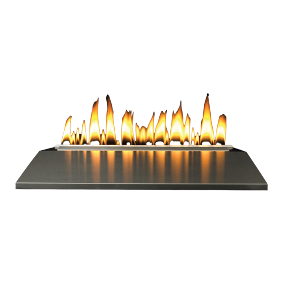
Page 18: Operation Instructions/Flame Appearance
OPerATION INSTrucTIONS/FLAMe APPeArANce Flames from the pilot (near the center of the burner) as well TOP COVER ASSEMBLY as the main flame should be visually checked as the burner assembly is installed and initially operated. In normal operation at full rate, the flame appearance should be random yellow flames above the burner. -
Page 19: Wiring - Vfrl Models
wIrING - VFrL MODeLS On a circulating vent-free firebox, it may be possible to install the Thermostats are not approved on vented decorative remote control receiver behind the bottom operable louver. appliances. Refer to remote control installation and operating instructions for Label all wires prior to disconnection when servicing controls. -
Page 20: Vfrl(18,24,30) Lighting Instructions
VFRL(18,24,30) LIGHTING INSTRUCTIONS FOr yOur SAFeTy reAD BeFOre LIGHTING wArNING: If you do not follow these instructions exactly, a fire or explosion may result causing property damage, personal injury or loss of life. A. This appliance has a pilot which must be lighted by department. -
Page 21: Vfrl1810(N,P) Lighting Instructions
VFRL1810(N,P) LIGHTING INSTRUCTIONS FOr yOur SAFeTy reAD BeFOre LIGHTING wArNING: If you do not follow these instructions exactly, a fire or explosion may result causing property damage, personal injury or loss of life. A. This appliance has a pilot which must be lighted by department. -
Page 22: Vfil Series Operating Instructions
VFIL SerIeS OPerATING INSTrucTIONS Thermostats are not approved on vented decorative appliances. Label all wires prior to disconnection when servicing con- trols. Wiring errors can cause improper and dangerous op- eration. Verify proper operation after servicing. MANUAL KNOB GAS INLET The VFIL series Loft Burners operate with a GV60 battery- (3/8 NPT) powered electronic remote ignition and control system. -
Page 23: Vfil Series Remote Electronic Ignition And Control System
VFIL SerIeS reMOTe eLecTrONIc IGNITION AND cONTrOL SySTeM APPLIcATION Timer/Thermostat RF GV60 is a battery-powered electronic and control system Remote Handset for gas appliances with pilot burners and ODS systems. G6R-H3T GeNerAL NOTeS radio Frequency remote 433.92 MHz for Europe; 315 MHz for U.S. (FCC ID: RTD-G6R) and for Canada (IC: 4943A-G6R). - Page 24 VFIL SerIeS reMOTe eLecTrONIc IGNITION AND cONTrOL SySTeM AuTOMATIc OPerATION Standard, Display, Timer/Thermostat rF remote Hand- wArNING • Simultaneously press and hold the OFF and (large Wiring of valve and receiver must be completed before flame) buttons until a short beep confirms the start se- starting ignition.
- Page 25 VFIL SerIeS reMOTe eLecTrONIc IGNITION AND cONTrOL SySTeM SeTTING THe TIMe NOTe: The display shows the set temperature every 30 Display, Timer/Thermostat rF remote Handsets seconds. • The display will flash after either: SeTTING THe TeMPerATure a. Installing the battery or •...
-
Page 26: Vfil Series Remote Electronic Ignition And Control System
VFIL SerIeS reMOTe eLecTrONIc IGNITION AND cONTrOL SySTeM 7. With the MANUAL knob in MAN position a manual pilot Location of receiver valve operator and piezo igniter are accessible. When the RF-receiver is placed in the appliance, the sur- rounding metal can reduce reception considerably. The Ignition with match: position of th antenna on the receiver also influences re- Fully push down manual pilot valve operator and hold... -
Page 27: Vfil(18,24,30) Lighting Instructions
VFIL(18,24,30) LIGHTING INSTRUCTIONS FOr yOur SAFeTy reAD BeFOre LIGHTING wArNING: If you do not follow these instructions exactly, a fire or explosion may result causing property damage, personal injury or loss of life. A. BEFORE LIGHTING, smell all around the appliance area B. -
Page 28: Vfil(18,24,30) Wiring Diagram
VFIL(18,24,30) WIRING DIAGRAM Main Valve Knob Manual Knob Piezo Igniter Connection for manual ignition Combination Control ON/OFF Switch Interrupter Block 8 Wire Cable Thermo Current Cable #2 or ON/OFF Switch with Soldered Cable Thermo Current Thermocouple Cable #1 Ignition Cable RF Antenna SPARK Battery... -
Page 29: Pilot Flame Characteristics
PILOT FLAMe cHArAcTerISTIcS Incorrect Pilot Flame Pattern for VFrL Figures 23 and 24 show a correct pilot flame pattern. The correct flame will be blue and will extend beyond the PILOT THERMOPILE thermocouple. The flame will surround the thermocouple (VFRL ONLY) just below the tip. -
Page 30: Cleaning And Servicing
PILOT FLAMe cHArAcTerISTIcS cleaning and Maintenance/Pilot Oxygen Depletion Sensor Pilot (Figures 27 and 28) When the pilot has a large yellow tip flame, clean the Oxygen Depletion Sensor as follows: 1. Clean the ODS pilot by loosening nut B from the pilot tubing. -
Page 31: Troubleshooting Symptoms, Possible Causes And Corrections
TrOuBLeSHOOTING SyMPTOMS, POSSIBLe cAuSeS AND cOrrecTIONS 1. When ignitor button is pressed, there is no spark at 7. ODS/pilot lights but flame goes out when control ODS/pilot. knob is released. a. Ignitor electrode positioned wrong - Replace pilot. a. Control knob not fully pressed in - Press in control b. -
Page 32: Decorative Top Cover Accessory Installation
DecOrATIVe TOP cOVer AcceSSOry INSTALLATION The Decorative Top Cover accessory options are available for your Installation Loft Burner. Choose the proper size Decorative Top Cover listed Addition of the Decorative Top Cover accessory should be for use with the Loft burner assembly. performed after the Loft burner has been fully installed, se- cured and tested for leaks. - Page 33 DecOrATIVe AcceSSOry INSTALLATION wArNING: Failure to position the parts in accordance with To install the Decorative Glass, cut off a corner of the plastic the diagrams and instructions below or failure bag and proceed to apply the glass to the rear shelf on the to use only parts specifically approved for use Loft burner (area behind the burner).
-
Page 34: Vfil Parts List
VFIL PArTS LIST Attention: When ordering parts, it is very important that part number and description of part coincide. PArT NO INDeX DeScrIPTION VFIL18 VFIL24 VFIL30 26526 26543 26551 TOP COVER ASSEMBLY R10410 R10411 R10412 TUBE BURNER R7624 R7624 R7624 AIR SHUTTER R7572 R7572... -
Page 35: Vfil Parts View
VFIL PArTS VIew TEMP 26532-5-0311 Page 35... -
Page 36: Vfrl Parts List
VFrL PArTS LIST Attention: When ordering parts, it is very important that part number and description of part coincide. PArT NO INDeX DeScrIPTION VFrL1810 VFrL18 VFrL24 VFrL30 26526 26526 26543 26551 TOP COVER ASSEMBLY R10477 R10410 R10411 R10412 TUBE BURNER R7624 R7624 R7624... -
Page 37: Vfrl Parts View
VFrL PArTS VIew 26532-5-0311 Page 37... -
Page 38: Master Parts Distributor List
For the current list, please click on the Master Parts button at www.empirecomfort.com. Please note: Master Parts Distributors are independent businesses that stock the most commonly ordered Original Equip- ment repair parts for Heaters, Grills, and Fireplaces manufactured by Empire Comfort Systems Inc. Dey Distributing... -
Page 39: Service Notes
APPLIANce SerVIce HISTOry Date Dealer Name Service Technician Name Service Performed/Notes 26532-5-0311 Page 39... - Page 40 Empire Comfort Systems Inc. EMPIRE EMPIRE 918 Freeburg Ave. Belleville, IL 62220 If you have a general question about our products, please e-mail us at info@empirecomfort.com. If you have a service or repair question, please contact your dealer. Comfort Systems www.empirecomfort.com...
Need help?
Do you have a question about the VFRL1810 Series and is the answer not in the manual?
Questions and answers