Table of Contents
Advertisement
www.reebokfitness.com
USER'S MANUAL
Model No. RBTL59211.0
Serial No.
Write the serial number in the space
above for reference.
Serial Number
Decal
QUESTIONS?
If you have questions, or if parts
are damaged or missing, DO NOT
CONTACT THE STORE; please
contact Customer Care.
IMPORTANT: Please register this
product (see the limited warranty
on the back cover of this manual)
before contacting Customer Care.
CALL TOLL-FREE:
1-877-994-4999
Mon.–Fri. 6 a.m.–6 p.m. MT
Sat. 8 a.m.–4 p.m. MT
ON THE WEB:
www.reebokservice.com
CAUTION
Read all precautions and instruc-
tions in this manual before using
this equipment. Save this manual
for future reference.
Advertisement
Table of Contents

Subscribe to Our Youtube Channel
Related Manuals for Reebok Competitor RT5.1


Summary of Contents for Reebok Competitor RT5.1
- Page 1 www.reebokfitness.com USER’S MANUAL Model No. RBTL59211.0 Serial No. Write the serial number in the space above for reference. Serial Number Decal QUESTIONS? If you have questions, or if parts are damaged or missing, DO NOT CONTACT THE STORE; please contact Customer Care. IMPORTANT: Please register this product (see the limited warranty on the back cover of this manual)
-
Page 2: Table Of Contents
TABLE OF CONTENTS WARNING DECAL PLACEMENT ............. . 2 IMPORTANT PRECAUTIONS . -
Page 3: Important Precautions
IMPORTANT PRECAUTIONS WARNING: To reduce the risk of serious injury, read all important precautions and instructions in this manual and all warnings on your treadmill before using your treadmill. ICON as- sumes no responsibility for personal injury or property damage sustained by or through the use of this product. - Page 4 DANGER: 20. Never leave the treadmill unattended while Always unplug the power it is running. Always remove the key, unplug cord immediately after use, before clean- the power cord, and press the power switch ing the treadmill, and before performing the into the off position when the treadmill is not maintenance and adjustment procedures in use.
-
Page 5: Before You Begin
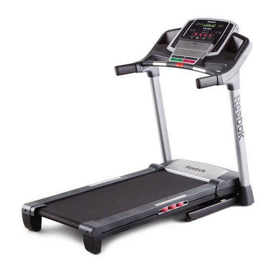
BEFORE YOU BEGIN Thank you for selecting the revolutionary reading this manual, please see the front cover of this REEBOK COMPETITOR RT 5.1 treadmill. The manual. To help us assist you, please note the product ® COMPETITOR RT 5.1 treadmill offers an impres- model number and serial number before contacting us. -
Page 6: Part Identification Chart
PART IDENTIFICATION CHART Use the drawings below to identify small parts used for assembly. The number in parentheses below each draw- ing is the key number of the part, from the PART LIST near the end of this manual. The number following the key number is the quantity used for assembly. -
Page 7: Assembly
ASSEMBLY • To hire a service technician to assemble this • To identify small parts, see page 6. product in your home, call 1-800-445-2480. • Assembly requires the following tools: • Assembly requires two persons. the included hex key • Place all parts in a cleared area and remove the packing materials. -
Page 8: The Upright Wire
2. See the inset drawing. Cut the plastic tie near the Upright Wire (88). Plastic Tie Attach a Wheel (93) to the Base (91) with a 3/8" x 2" Bolt (9) and a 3/8" Nut (10). Do not over- tighten the Nut; the Wheel must turn freely. Press a Base Cap (110) into the Base (91). -
Page 9: 2" Bolt (9) And A 3/8" Nut (10). Do Not Over
4. Hold the Right Upright (81) against the Base (91). Be careful not to pinch the Upright Wire (88). Insert two 3/8" x 4" Screws (7) and a 3/8" x 1 1/2" Screw (8) with three 3/8" Star Washers (11) into the Right Upright. Partially tighten the 3/8"... - Page 10 6. Hold the Left Upright (80) against the Base (91). Insert two 3/8" x 4" Screws (7) and a 3/8" x 1 1/2" Screw (8) with three 3/8" Star Washers (11) into the Left Upright. Partially tighten the 3/8" x 4" Screws (7) until the heads of the Screws touch the Left Upright (80);...
- Page 11 9. Attach the Right Handrail (85) to the Right Upright (81) with two 5/16" x 1" Screws (5), two 5/16" Star Washers (13), and a 5/16" x 1 1/4" Bolt (2). Do not fully tighten the Screws and Bolt yet. Attach the Left Handrail (84) in the same way.
-
Page 12: Wire Tie
12. With the help of a second person, hold the con- sole assembly near the Right Handrail (85). Connect the Upright Wire (88) to the console Console wire. See the inset drawing. The connectors Assembly should slide together easily and snap into place. - Page 13 14. Firmly tighten the four 3/8" x 4" Screws (7) and the two 3/8" x 1 1/2" Screws (8) (only one side is shown). Slide the Left Base Cover (86) and the Right Base Cover (87) downward. 15. Slide the Left Handrail Cover (83) onto the Left Handrail (84).
- Page 14 16. Hold the Left Upright Cover (78) against the console assembly. Align the holes in the Left Upright Cover with the holes in the Left Upright (80). Attach the Left Upright Cover with three #8 x 1/2" Screws (16). Attach the Right Upright Cover (79) to the Right Upright (81) in the same way.
- Page 15 18. Raise the Frame (53) to the position shown. Have a second person hold the Frame until this step is completed. Orient the Storage Latch (52) so that the large barrel and the latch knob are oriented as shown. Attach the Latch Bracket (51) and Storage Latch (52) to the Base (91) with two 3/8"...
-
Page 16: Operation And Adjustment
OPERATION AND ADJUSTMENT HOW TO CONNECT THE POWER CORD nominal 120-volt circuit capable of carrying 15 or more amps. To avoid overloading the circuit, do Use a Surge Suppressor not plug other electrical devices, except for low- power devices such as cell phone chargers, into the surge suppressor or into an outlet on the same Your treadmill, like other electronic equipment, can be damaged by sudden voltage changes in your home’s... - Page 17 CONSOLE DIAGRAM FEATURES OF THE CONSOLE You can even listen to your favorite workout music or audio books with the console’s stereo sound system The treadmill console offers an impressive array of while you exercise. features designed to make your workouts more effec- tive and enjoyable.
- Page 18 HOW TO TURN ON THE POWER HOW TO USE THE MANUAL MODE IMPORTANT: If the treadmill has been exposed to 1. Insert the key into the console. cold temperatures, allow it to warm to room tem- perature before turning on the power. If you do not See HOW TO TURN ON THE POWER at the left.
- Page 19 5. Follow your progress with the displays. To measure your heart The matrix—When rate, stand on you select the manual the foot rails mode, the matrix will and hold the display a track that rep- pulse bar with resents 1/4 mile (400 your palms on m).
- Page 20 HOW TO USE AN ONBOARD WORKOUT grammed for the next segment, the new speed and/ or incline setting will flash in the displays for a few 1. Insert the key into the console. seconds. The treadmill will automatically adjust to the new speed and/or incline setting.
- Page 21 HOW TO USE THE WEIGHT LOSS CENTER 4. Follow your progress with the displays. 1. Insert the key into the console. See step 5 on page 19. Note: The calorie goal is an estimate of the See HOW TO TURN ON THE POWER on page 18. number of calories that you will burn during 2.
- Page 22 HOW TO USE AN IFIT WORKOUT the button, the treadmill will automatically adjust to the first speed and incline settings of the workout. To purchase iFit cards at any time, go to www.iFit.com Hold the handrails and begin walking. or call the telephone number on the front cover of this manual.
- Page 23 THE INFORMATION MODE An "E" for English miles or an "M" for metric kilome- The console features an information mode that keeps ters will appear in the right track of the total distance that the walking belt has display. Press the Speed moved and the total number of hours that the treadmill increase button to change has been used.
-
Page 24: How To Fold And Move The Treadmill
HOW TO FOLD AND MOVE THE TREADMILL HOW TO FOLD THE TREADMILL HOW TO MOVE THE TREADMILL To avoid damaging the treadmill, adjust the incline Before moving the treadmill, fold it as described at the to the lowest position before you fold the treadmill. left. -
Page 25: Troubleshooting
TROUBLESHOOTING Most treadmill problems can be solved by following d. If the treadmill still will not run, please see the front the simple steps below. Find the symptom that cover of this manual. applies, and follow the steps listed. If further as- sistance is needed, see the front cover of this SYMPTOM: The console displays remain lit when manual. - Page 26 Remove the three #8 x 3/4" Screws (1) and care- begin calibrating, press the Stop button again, and fully pivot the Motor Hood (61) off. then press the Incline increase or decrease button again. When the incline is calibrated, remove the key from the console.
- Page 27 SYMPTOM: The walking belt is off-center or slips b. If the walking belt slips when walked on, first re- when walked on move the key and UNPLUG THE POWER CORD. Using the hex key, turn both idler roller screws a. If the walking belt is off-center, first remove the clockwise, 1/4 of a turn.
-
Page 28: Exercise Guidelines
EXERCISE GUIDELINES Burning Fat—To burn fat effectively, you must exer- WARNING: cise at a low intensity level for a sustained period of Before beginning this time. During the first few minutes of exercise, your or any exercise program, consult your physi- body uses carbohydrate calories for energy. - Page 29 SUGGESTED STRETCHES The correct form for several basic stretches is shown at the right. Move slowly as you stretch —never bounce. 1. Toe Touch Stretch Stand with your knees bent slightly and slowly bend forward from your hips. Allow your back and shoulders to relax as you reach down toward your toes as far as possible.
-
Page 30: Part List
PART LIST Model No. RBTL59211.0 R0412A Key No. Qty. Description Key No. Qty. Description #8 x 3/4" Screw Latch Bracket 5/16" x 1 1/4" Bolt Storage Latch 1/4" x 1/2" Screw Frame #10 x 3/4" Screw Idler Roller Bracket 5/16" x 1" Screw Right Handrail Cover #8 x 1"... - Page 31 Key No. Qty. Description Key No. Qty. Description Left Tray Crossbar Right Tray 5/16" Flat Washer Console Frame #10 x 3/4" Flat Head Screw Ground Wire Base Cap Console Clamp – User’s Manual Console Back Note: Specifications are subject to change without notice. For information about ordering replacement parts, see the back cover of this manual.
-
Page 32: Exploded Drawing
EXPLODED DRAWING A Model No. RBTL59211.0 R0412A... - Page 33 EXPLODED DRAWING B Model No. RBTL59211.0 R0412A...
- Page 34 EXPLODED DRAWING C Model No. RBTL59211.0 R0412A...
- Page 35 EXPLODED DRAWING D Model No. RBTL59211.0 R0412A...
-
Page 36: Ordering Replacement Parts
ORDERING REPLACEMENT PARTS To order replacement parts, please see the front cover of this manual. To help us assist you, be prepared to provide the following information when contacting us: • the model number and serial number of the product (see the front cover of this manual) •...
Need help?
Do you have a question about the Competitor RT5.1 and is the answer not in the manual?
Questions and answers