Table of Contents
Advertisement
Advertisement
Table of Contents
Troubleshooting

Related Manuals for Hemisphere GPS eDriveTC


Summary of Contents for Hemisphere GPS eDriveTC
- Page 1 Outback eDrive User Guide Part No. 875-0171 Rev. C1...
- Page 2 U.S. Patents No. 6,539,303 and No. 6,711,501. The OUTBACK Hitch™ automated hitch control system is protected under U.S. Patent No. 6,631,916. The OUTBACK eDriveTC™ GPS assisted steering system is protected under U.S. Patent No. 7,142,956. Other U.S. and international patents pending.
-
Page 4: Warranty Notice
Warranty Notice Covered Products This warranty covers all products manufactured by Hemisphere GPS (the "Products"). Hemisphere GPS Limited Warranty Hemisphere GPS hereby warrants solely to the end purchaser of the Products, subject to the exclusions and procedures set forth herein below, that the Products sold to such end purchaser shall be free, under normal use and maintenance, from defects in material and workmanship for a period of 12 months from delivery to such end purchaser. - Page 5 For any questions regarding warranty service or to obtain information regarding the location of any of Hemisphere GPS' approved service centers, contact Hemisphere GPS at the following address: Outback Guidance Technical Support Hemisphere GPS 2207 Iowa Street Hiawatha, Kansas 66434 Phone 800.247.3808 Fax 785.742.4584...
-
Page 6: Table Of Contents
Initial system startup sequence 16 3: eDriveTC Operation ....23 Guidance overview ..... . .24... - Page 7 For Contour Driving 26 Auto-Disengage ......27 Manual Disengage ..... . .28 Auto-Engage .
- Page 8 User Guide C: Sales and Service Information ... .51 Contacting the Factory 51 Outback eDriveTC Extended Service Plan (ESP) Summary 53 Limited Outback eDriveTC Extended Service Plan 54...
-
Page 10: 1: Overview
1: Overview Product Overview What’s Included Parts Listing... -
Page 11: Product Overview
A complete system consists of an Outback S2 (sold separately), an equipment model specific eDriveTC install kit, and the eDriveTC electronic components. This manual covers the installation of the electronic components along with the eDriveTC setup and operation. -
Page 12: What's Included
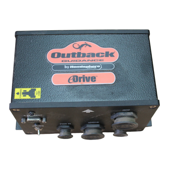
User Guide What’s Included The following equipment is included with the Outback eDriveTC: • eDriveTC console • CAN/Power cable • CAN/Expansion cable • CAN/Battery cable • Auxiliary power cable • Tie straps • Screws (#8 x 3/4”) Figure 1-1. Outback eDriveTC and Equipment... -
Page 13: Parts Listing
1: Overview Parts Listing... - Page 14 Table 1-1: Outback eDriveTC Guidance System Ref. Description Qty. Outback S2 (required) Outback External CAN Device (optional) 051-0101-001# CAN/Power Cable, OKB-eDriveTC - 10ft Lg/15ft Lg, WP 051-0067-005# CAN/Expansion Cable, OBK-eDriveTC - 10ft 054-0065-000# CAN/Battery Cable, OBK-eDriveTC - 5ft Lg. 806-1007-03A Console, OBK-eDriveTC 054-0044-003# Auxiliary Power Cable, OBK-eDriveTC - 12ft Lg.
- Page 15 1: Overview...
-
Page 16: 2: Getting Started
2: Getting Started Overview Installing the eDriveTC Powering the Unit System Configuration... -
Page 17: Overview
2: Getting Started Overview Before using the Outback eDriveTC for the first time, you’ll need to: • install the eDriveTC • turn on the power, • and set basic features. Installing the eDriveTC Exchange Power Cable - If the power cable currently used with the S2 does not have a second CAN connector then it will need to be replaced by the CAN/Power cable in the eDriveTC package. - Page 18 Note: The Outback eDriveTC may also be used in combination with an optional Outback external CAN device (example: Outback 360.) If an external CAN device is already installed, it is not necessary to exchange the power cable. Instead, a three- connector CAN/Expansion cable is installed between the external CAN device and the eDriveTC.
- Page 19 Route both cables into the cab, securing with tie straps. Avoid sharp edges and pinch points which could damage the cables and cause a short circuit. Outback electronic components are designed for 12 volt Note: negative ground automotive systems. Make certain there are good solid connections to 12 volts and ground.
- Page 20 CAN/Battery Cable Use this criteria when mounting the eDriveTC unit: Securely mount the eDriveTC unit to the vehicle with screws on the eDrive console flanges. (See Figure 2-2 on page 12.) Have the top of the eDriveTC console face upwards according to...
- Page 21 2: Getting Started Ensure that the eDriveTC unit is on a surface that is level when the machine is level with the ground. (See Figure 2-2.) Follow the instructions on the new label with regards to the mounting orientation. The default is to mount the eDriveTC unit parallel to the line of travel with the connectors towards the left.
- Page 22 User Guide Install Auxiliary Power Cable: - Connect the Auxiliary Power cable to the eDriveTC console. Twist the connector firmly until it locks into place. Install CAN/Power Cable: - Connect the CAN/ Power cable to the eDriveTC console. Twist the...
- Page 23 2: Getting Started Install Valve Control Cable: - Connect the valve control cable (supplied with the model specific installation kit) to the eDriveTC console. Twist the connector firmly until it locks into place. Valve Control Cable Install Steering Wheel Switch Cable: -...
-
Page 24: Powering The Unit
Powering the Unit To power up both units Turn on the power switches of the Outback S2 and eDriveTC in any order. The Outback S2 will boot up and begin acquiring a DGPS signal. The eDriveTC will establish communication with the S2 and wait for the DGPS signal to be acquired. -
Page 25: System Configuration
System Configuration Configuration of the Outback eDriveTC is accomplished through the menu system of either the Outback S2, or an external serial device. During power-up, the eDriveTC is detected, and additional menu options are included to configure the eDriveTC for operation. - Page 26 Test drive the vehicle in straight guidance mode, and fine tune the steering control rate for smooth response and minimum tracking errors. See Appendix B for tips on fine tuning. Table 2-2: eDriveTC Setup Menu Options Display Menu Item Defaults...
- Page 27 2: Getting Started Table 2-2: eDriveTC Setup Menu Options Display Menu Item Defaults Description Sequence Steering Adjust <=DN UP=> <<<DN UP>>> Press DOWN ARROW to ENTER TO STOP ENTER TO STOP move vehicle steering to the left. Press ENTER to stop at left extreme.
- Page 28 User Guide Tilt Compensation setup sequence: - After completing initial system startup sequence, perform the following tilt setup sequences prior to field operation. Note: Be sure the vehicle is parked on a level surface before calibrating the accelerometer value. It may be necessary to use a long bubble level against a rigid vehicle surface to verify that it is indeed level.
- Page 29 (This will provide the degree of level.) 18. Scroll down to Diagnostics. 19. Press the ENTER button to show the eDriveTC version and tilt angle. The angle value displayed is the calibrated vehicle slope from level. The version number is the current eDriveTC software...
- Page 30 User Guide Table 2-3: Tilt Setup Menu (only always present in eDriveTC) Menu Item Display Sequence Defaults Description Tilt Comp Tilt Comp [On, Off] Allows the user to > Off Default = Off enable or disable the tilt sensor functionality.
- Page 31 2: Getting Started Gyro Calibration: - The eDriveTC uses a rate gyro to improve guidance and control the steering. This is automatically calibrated after power up, while moving and using GPS data. It requires some turns and straight runs to optimize its performance. Users may find it beneficial to momentarily slow down beneath the minimum speed, 1 M.P .H.
-
Page 32: 3: Edrivetc Operation
3: eDriveTC Operation Guidance Overview Auto-Disengage Auto-Engage... -
Page 33: Guidance Overview
3: eDriveTC Operation Guidance overview Operation of the Outback eDriveTC is an intuitive extension of the stand-alone Outback guidance modes. If you are a first time user of Outback products, carefully review the instruction booklet provided with the Outback guidance controller. -
Page 34: For Straight Driving
User Guide For Straight Driving Enter the STRAIGHT GUIDANCE mode and establish the guideline following the prompts given by the guidance controller. Manually steer the vehicle close to the guideline and engage the eDriveTC. At the end of the pass, manually turn the vehicle around and line up... -
Page 35: For Contour Driving
Anytime you approach a previous pass, the Outback guidance controller begins to display guidance. Manually steer the vehicle close to the guideline and engage the eDriveTC. For sharp turns, slow down or manually steer the vehicle. In either straight or contour mode, the eDriveTC automatically disengages when manually steered off the guideline. -
Page 36: Auto-Disengage
The vehicle’s ground speed is less than 1 m.p.h. or greater than 20 m.p.h. Note: If your system has RTK corrections, the eDriveTC will automatically disengage if your ground speed is less than 0.25 m.p.h. or greater than 20 m.p.h. -
Page 37: Manual Disengage
If no previous pass is found nearby, the display will show LOGGING PASS, and the eDriveTC is disabled. Once a previous pass has been detected, guidance indicators will be displayed, and the eDriveTC can be engaged. -
Page 38: Auto-Engage
ENTER button. The auto-engage feature may be turned on or off through the eDriveTC setup menu. To operate with the auto-engage: Initiate guidance and manually engage the eDriveTC, using the normal operating procedure. - Page 39 Note: For safety reasons, there is a time-out of 45 seconds for the auto-engage to operate. If the auto-engage does not re- engage with in this time, the indicator light will stop flashing and eDriveTC must be manually re-engaged by pressing the ENTER button.
-
Page 40: 4: Troubleshooting
Troubleshooting Fine Tuning Performance Troubleshooting Tips Vehicle Type Setup Table... -
Page 41: Fine-Tuning Performance
Proper setting and periodic adjustments of the steering control rate are required to achieve smooth steering response, minimize tracking errors, and optimize the eDriveTC’s performance. Increasing the Steering Control Rate by using the control knob on the steering block (the control block may vary according to... - Page 42 The eDriveTC tracking errors in contour guidance can be minimized by reducing travel speed on sharp curves. Note: The overall accuracy of the eDriveTC system depends on many factors. Refer to Appendix A: Making the Most of Automated Steering for more information.
-
Page 43: Troubleshooting Tips
Verify Outback S2 application software is the appropriate version, “6.0 and above. ” • Verify the S Present light is lit on the eDriveTC console. • Check CAN communication cable and connections. No Steering Output at eDriveTC Steering Adjust Menu: - •... -
Page 44: Vehicle Type Setup Table
User Guide Vehicle Type Setup Table GPS Antenna Machine Type Sensitivity Dampening Location MFWD or 2WD Row- Leading edge of the Crop Tractor vehicle cab Articulated 4WD Leading edge of the 10, In some cases it Tractor vehicle cab... - Page 45 4: Troubleshooting GPS Antenna Machine Type Sensitivity Dampening Location Track Machines Leading edge of the (Differential Steering vehicle cab only, use Track Mode. A CaseIH QuadTrac is not considered a track machine because it does not use differential steering, refer to Articulated 4WD tractors)
-
Page 46: Appendices
Appendices A: Making the Most of Automated Steering B: Frequently Asked Questions C: Sales and Service Information... -
Page 47: A: Making The Most Of Automated Steering
Appendices A: Making the Most of Automated Steering Hemisphere GPS Crescent Receiver Technology sets new standards for accuracy and flexibility in precision ground agriculture. However, in-the-field accuracy for automated steering applications is influenced by a variety of factors, not just the inherent accuracy of the GPS system. - Page 48 User Guide Figure 5-2. GPS antenna installed on the leading edge of the vehicle cab and centered left to right. It is also important to install the GPS antenna in the center (left and right) of the vehicle. This prevents swath offsets resulting in skips and overlaps.
- Page 49 Appendices Steering Controller and Tilt Compensation Installation - The automated steering controller contains sensors for the yaw (left/ right turn) and roll (tilt side to side) axes so it is important to install it in the appropriate orientation. For proper operation, calibrate the tilt compensation sensor according to the operator’s manual.
-
Page 50: Machine / Vehicle Control
User Guide Machine / Vehicle Control Automated Steering Hydraulic Tuning - It is necessary to adjust the steering speed on the automated steering hydraulic valve to optimize machine control accuracy. Make adjustments when the vehicle hydraulic oil is at operating temperature. - Page 51 Appendices change in the vehicle or application. For example, adding an implement with significantly more draft, adding duals or ballasting, and/or dramatically increasing operational ground speed. Vehicle Setup: Steering Maintenance, Ballasting and Stance, Traction Aids - It is important to consider the physical characteristics of a vehicle that may affect the ability of the automated steering system to perform at an optimal level.
-
Page 52: Implement Tracking
User Guide Additionally, a wider wheel stance with front and rear duals (where applicable) will dramatically improve vehicle stability allowing for increased steering accuracy. Figure 5-5. Machine ballasted with full set of front suitcase weights and rear wheel weights. Wide stance with duals front and rear for stability and traction. - Page 53 Appendices Drawn Implements - Implements with long drawbar connections to the vehicle can often move back and forth behind a vehicle that is driving in a straight path. It is important to use stabilizing methods such as disk coulters to help the implement track inline with the towing vehicle.
-
Page 54: Field Conditions
User Guide implement to the front of the vehicle to prevent deflection in the outer sections of the implement. Figure 5-6. Vehicle 3-point sway block set tight and spaced evenly on both sides. Field Conditions Field conditions can also play a role in accuracy. Smooth, flat fields with uniform tilth will obviously allow for the best possible accuracy. -
Page 55: Consistent Accuracy And Increased Productivity
Appendices Contour Terraces - Similar to rolling terrain, but may require the use of contour guidance mode. Contour guidance mode uses a smoothing feature to gradually reduce curve severity with every consecutive pass. Therefore, each pass will have some amount of error at the transitions of each curve. In addition, drawn implements do not track directly behind the tow vehicle when navigating curves inherently reducing accuracy. -
Page 56: B: Frequently Asked Questions
(part umber 876-0082) for more information. Does it make a difference which eDriveTC steering hose is connected to the A and B ports of the eDriveTC hydraulic block? No, the steering outputs of the eDriveTC hydraulic block can be reversed and easily corrected. When performing the steering adjust function, the vehicle steering should turn left with the down arrow and right with the up arrow. - Page 57 Each time one the eDriveTC is disengaged then the system is reset and must go back through the auto-engage routine. See pages 27 to 30 in the eDriveTC User Guide for eDriveTC auto-disengage, manual disengage and auto-engage criteria.
- Page 58 No, under normal field operation the vehicle steering wheel should not turn when eDriveTC is steering. When performing the steering adjust function the steering wheel may begin to turn if eDriveTC after the steering cylinders have reached the end of their stroke. If...
- Page 59 13. Why does my manual steering seem stiff with eDriveTC installed? If the system uses a closed center eDriveTC valve then the load sense signal from the manual steering unit is not being correctly transmitted; make sure that the eDriveTC is installed properly.
-
Page 60: C: Sales And Service Information
User Guide C: Sales and Service Information Contacting the Factory U.S: Canada: Outback Guidance Outback Canada Hemisphere GPS Hemisphere GPS 2207 Iowa Street 3244 Portage Avenue Hiawatha, KS 66434 Winnipeg, MB R3K 0Y9 CANADA ONLINE: http://www.outbackguidance.com PHONE: Monday Through Friday 8AM-5PM U.S. Central Time •... - Page 61 Appendices U.S. REGIONAL SALES OFFICES: • Outback Nebraska - Hastings, NE 1-877-777-6142 • Outback Texas - Hewitt, TX 1-866-857-4448 • Outback Dakotas - Watertown, SD 1-888-825-6031 • Outback Illinois- Jacksonville, IL 1-888-477-6070...
-
Page 62: Outback Edrivetc Extended Service Plan (Esp Summary
User Guide Outback eDriveTC Extended Service Plan (ESP) Summary U.S. and Canada Only Item Standard Term Extended Term Price Free $299 Term 1 Year ESP 3 Year ESP (Standard +2 Years) Exchange Service Software Revision Updates No Charge No Charge... -
Page 63: Limited Outback Edrivetc Extended Service Plan
Appendices Limited Outback eDriveTC Extended Service Plan The Outback eDriveTC ESP (U.S. and Canada only) applies only to the non-software portions of the electronic components of the product, including the console and related cables. Coverage for the mechanical portions of the Outback eDriveTC is described in the warranty notice. - Page 64 No one is authorized to alter, modify or enlarge this Limited Outback eDriveTC Extended Service Plan nor the exclusions, limitations, and...
- Page 65 Appendices...
- Page 66 www.hemispheregps.com e-mail: info@hemispheregps.com...
Need help?
Do you have a question about the eDriveTC and is the answer not in the manual?
Questions and answers
Have a outback edrive hydraulic can’t get power to valve block for auto steer
Possible issues with the Hemisphere GPS eDriveTC not providing power to the valve block for auto steer include:
1. The eDriveTC is not powered on — ensure the power switch is turned on.
2. The Outback S2 is not acquiring a DGPS signal — eDriveTC waits for this signal before engaging.
3. The system is automatically disengaged — this can happen if:
- Position error exceeds 6 feet or 10% of swath width.
- The steering wheel is manually turned.
- Vehicle speed is below 1 mph or above 20 mph (or below 0.25 mph with RTK corrections).
4. The eDriveTC is in a non-operational mode or menu.
5. Steering hoses may be incorrectly connected — reversing A/B ports and confirming direction may be necessary.
Check these conditions to determine the cause.
This answer is automatically generated