Life Fitness LIFECYCLE R1 Owner's Manual
Recumbent exercise bikes
Hide thumbs
Also See for LIFECYCLE R1:
- Assembly instructions (2 pages) ,
- User manual (22 pages) ,
- Parts list (7 pages)
Table of Contents
Advertisement
Advertisement
Table of Contents

Related Manuals for Life Fitness LIFECYCLE R1


Summary of Contents for Life Fitness LIFECYCLE R1
- Page 1 R1 / R3 RECUMBENT LIFECYCLE® EXERCISE BIKES Owner’s Manual 8975001 REV B-2...
- Page 3 5100 River Road Schiller Park, Illinois 60176 • U.S.A. 847.288.3300 • FAX: 847.288.3703 Service phone number: 800.351.3737 (toll-free within U.S.A., Canada) Bijdorpplein 25-31 Siemensstraße 3 2992 LB Barendrecht 85716 Unterschleißheim 5100 N River Road THE NETHERLANDS GERMANY Schiller Park, IL 60176 U.S.A Telephone: (+31) 180 646 644 Telephone: (+49) 89.31 77 51.0 (Germany) Telephone: (847) 288 3300...
- Page 4 FCC Warning - Possible Radio / Television Interference Note: Reorient or relocate the receiving antenna. • Increase the separation between the equipment and the receiver. • Connect the equipment into an outlet on a circuit different from that to which the receiver is connected. •...
- Page 5 R1 / R3 Recumbent Lifecycle ® Exercise Bike Overview ....... .
- Page 6 Life Fitness Recumbent Lifecycle ® Exercise Bike Models: Thank you for purchasing a Life Fitness bike. Before using this product please read this user manual in its entirety to ensure that you have the knowledge to safely and properly operate all of the features on your bike. We hope you...
- Page 7 Never insert objects into any openings in this product. If an object should drop inside, turn off the power, unplug the power cord from the outlet and carefully retrieve it. If the item cannot be reached, contact Life Fitness Customer Support Services.
- Page 8 • Never operate this appliance if it has a damaged cord or plug, if it is not working properly, if it has been dropped or damaged, or dropped into water. Contact Life Fitness Customer Support Services. • Never operate the appliance with the air openings blocked. Keep the air openings free of lint, hair, and the like.
- Page 10 Identify the following components after unpacking your Lifecycle. The tools needed for assembling the product are included. 50mm Button Head Screw 15mm Button Head Screw Flat Washer - 18mm O.D. 55mm Phillips Screw Lock Washer - 12.2mm O.D. 8mm Phillips Screw 40mm Button Head Screw with Locking Compound Flat Washer - 24mm O.D.
- Page 11 Rubber Bumper 50mm Button Head Screw 15mm Button Head Screw Sleeve Thick Flat Washer -16mm O.D. 60mm Hex Head Bolt 55mm Phillips Screw 12mm Large Head Phillips Screw Nylock Nut 12mm Phillips Screw with 40mm Button Head Screw Flat Washer - Locking Compound with Locking Compound 18mm O.D.
- Page 12 None Remove all packaging and place main components to the side of the box. Break box down in each of the four corners. Hardware Bag #1 (2, 50mm Button Head Screws) (2, 15mm Button Head Screws) 5mm Hex Head Wrench Locate and install the two LEVELER FEET (A) to the bottom of the REAR STABI- LIZER (B).With the bends facing rearward, attach the REAR STABILIZER (B) to the BASE UNIT (C) using two 50mm BUTTON HEAD SCREWS (1) from the top of the...
- Page 13 Hardware Bag #3 (1, 40mm Button Head Screw with Locking Compound) (1, 24mm Flat Washer) (1, Rubber Bumper Sleeve) (1, Rubber Bumper 1”) (1, 18mm Flat Washer) (2, 12mm Phillips Screws with Locking Compound) (2, 12mm Phillips Screws) (4, 55mm Phillips Screws) (4, 8mm Nylock Nuts) (4, 8mm Self-Tapping Phillips Screws) (4, 12mm Phillips Screws)
- Page 14 : Secure the SEAT BACK PAD (Q) to the SEAT BACK SUPPORT (R) using four 8mm NYLOCK NUTS (21) making sure the LOWER ADJUSTMENT STRAP is located behind the SUPPORT TUBES. Be careful not to allow the LOWER ADJUSTMENT STRAP to be caught between the SEAT BACK SUPPORT and the SEAT MOUNTING BRACK- ET.
- Page 15 Hardware Bag #4 (2, 100mm Hex Head Bolts) (5, Thick Flat Washers - 16mm O.D.) (2, 60mm Hex Head Bolts) (4, 12mm Phillips Screws) (4, Flat Washers - 12mm O.D.) (4, 15mm Button Head Screws) 13mm Socket Wrench, 5mm Hex Head Wrench, Phillips Screwdriver Locate the MONOCOLUMN (S).
- Page 16 Hardware Bag #5 (4, 12mm Phillips Screws) Phillips Screwdriver Remove the DISPLAY CONSOLE (DD) from its shipping carton. Position the DISPLAY CONSOLE above the DISPLAY CONSOLE BRACKET (EE). Connect the CONSOLE WIRE 15-pin connector (FF), HEART RATE WIRE 4-pin connector (GG), SUPPLEMENTAL POWER WIRE 2-pin connector (OO), and GROUND WIRE single spade (HH) (Green) to the corresponding CONNECTORS located on the back of the DISPLAY CONSOLE.
- Page 17 15mm Open End Wrench Locate the RIGHT PEDAL (JJ) (marked with an "R") and PEDAL STRAP (KK) (marked with an "R"). With the side of the PEDAL STRAP marked with an “R” fac- ing upward, slide the slotted end of the PEDAL STRAP through the left slot in the PEDAL.
- Page 18 Read the entire User Manual before setting up the Lifecycle exercise bike. Following all safety instructions in Section 1 move the bike to the location in which it will be used. See Section 7, for the dimensions of the footprint. Allow a distance of 4 feet (120 centimeters) between the bike and other objects or surfaces on either side.
- Page 19 The bike pedal safety straps keep the user's shoes on the pedals during a workout. The straps should fit comfortably, but they also should be tight enough to prevent shoes from slipping at any point in the pedaling rotation. Before working out, the user should test and adjust the tightness of the straps.
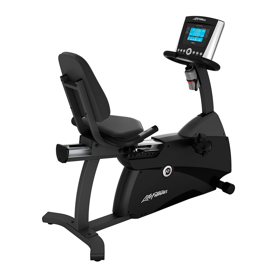
- Page 20 Two accessory trays (A) are mounted to the right of the seat on the R3 to provide storage for items such as water bot- tles, personal stereos, and cell phones. A Water Bottle Holder (B) is located on the monocolumn of the R1. Additionally, an integrated Reading Rack (C) for supporting a book or magazine is located at the base of the console.
- Page 21 Check to see that the power cord is fully plugged into the back of the Lifecycle exercise bike and into the wall. Make sure the power cord is fully seated into the back of the Lifecycle exercise bike. You may be in “Energy Saver Mode”. Press the “Energy Saver” button to No power.
- Page 23 The Life Fitness Lifecycle exercise bike is backed by the engineering excellence and reliability of Life Fitness and is one of the most rugged and trouble-free pieces of exercise equipment on the market today. Note: The following preventive maintenance tips will keep the Life Fitness exercise bike operating at peak performance: •...
- Page 24 WEEKLY MONTHLY BI-ANNUALLY 1. Please contact your dealer or Life Fitness Customer Service at 1-800-351-3737. 2. Verify the symptom and review the operating instructions and troubleshooting matrix. 3. Locate and document the serial number of the unit . The serial number plate is located on the front stabilizer, below the Please also have proof of purchase information available.
- Page 25 Drive Type: Poly -V belt-drive Power Requirements: 120 Volt (U.S.), 220 Volt (Europe), 240+ Volt (Australia) Note: Accessories: Water Bottle Holder & Reading Rack (R1) Two Accessory Trays & Reading Rack (R3) Resistance System: Eddy Current (R1) Generator (R3) Note: Length 56.5 in.
- Page 26 Non-Residential: Warranty void (this Product is intended for residential use only). If the Product or any warranted part must be returned to a service facility for repairs, Life Fitness will pay all shipping and insurance charges during the warranty period (within the United States only). The purchaser is responsible for ship- ping and insurance charges after the warranty has expired.
- Page 27 Warranties may vary outside the U.S. Contact Life Fitness for details. No one is authorized to change, modify or extend the terms of this limited warranty.