Table of Contents
Advertisement
Quick Links
IMPORTS, INC.
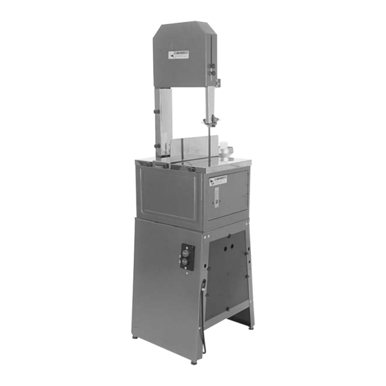
HUNTER'S MEAT CUTTING SAW
MODEL G1016
INSTRUCTION MANUAL
COPYRIGHT © 1995 BY GRIZZLY IMPORTS, INC.
WARNING: NO PORTION OF THIS MANUAL MAY BE REPRODUCED IN ANY SHAPE
OR FORM WITHOUT THE WRITTEN APPROVAL OF GRIZZLY IMPORTS, INC.
JULY, 1995. PRINTED IN USA
DISCONTINUED MACHINE MANUAL DISCLAIMER
THE INFORMATION IN THIS MANUAL REPRESENTS THE LAST CONFIGURATION OF THE MACHINE BEFORE IT WAS DISCONTINUED.
MACHINE CONFIGURATIONS MAY HAVE CHANGED AS PRODUCT IMPROVEMENTS WERE INCORPORATED. IF YOU OWN AN EARLIER VER-
SION OF THE MACHINE, THIS MANUAL MAY NOT EXACTLY DEPICT YOUR MACHINE . CONTACT CUSTOMER SERVICE IF YOU HAVE ANY
QUESTIONS ABOUT DIFFERENCES. PREVIOUS VERSIONS ARE NOT AVAILABLE ONLINE.
- - 1 1 - -
H H u u n n t t e e r r ' ' s s M M e e a a t t C C u u t t t t i i n n g g B B a a n n d d s s a a w w
Advertisement
Table of Contents

Related Manuals for Grizzly G1016


Summary of Contents for Grizzly G1016
-
Page 1: Instruction Manual
INSTRUCTION MANUAL COPYRIGHT © 1995 BY GRIZZLY IMPORTS, INC. WARNING: NO PORTION OF THIS MANUAL MAY BE REPRODUCED IN ANY SHAPE OR FORM WITHOUT THE WRITTEN APPROVAL OF GRIZZLY IMPORTS, INC. JULY, 1995. PRINTED IN USA DISCONTINUED MACHINE MANUAL DISCLAIMER THE INFORMATION IN THIS MANUAL REPRESENTS THE LAST CONFIGURATION OF THE MACHINE BEFORE IT WAS DISCONTINUED. -
Page 2: Table Of Contents
Introduction...1 Safety Rules for all Tools ...2 III. Electrical Requirements ...4 A. Circuit Loading...4 B. Grounding ...4 C. General Information...4 D. Word of Caution ...4 Site Planning...5 A. Working Clearances ...5 B. Lighting and Outlets ...5 Unpacking ...5 Piece Inventory ...6 VII. - Page 3 Table of Contents VIII. Adjustments ...12 A. Blade Tension ...12 B. Tracking ...13 C. Guide Blocks ...14 D. Support Bearings...15 E. Blade Removal and Replacement...16 F. Blade Guard ...16 Safety Rules for Bandsaws ...17 Operations ...18 A. General ...18 B. Test Run ...18 C.
-
Page 4: Introduction
The saw features a sheet steel body, easy to clean stainless steel table, and a 10 height. It comes equipped with a 1720 RPM, 1 HP motor. -
Page 5: Safety Rules For All Tools
II. Safety Rules for all Tools 1. KNOW YOUR POWER TOOL. Read the owner’s manual carefully. Learn the tool’s applications and limitations, as well as its hazards. 2. KEEP ALL GUARDS IN PLACE and in working order. 3. GROUND ALL TOOLS. If an adapter is used to accommodate a two-prong receptacle, the adapter plug must be attached to a known ground. - Page 6 Review all safety procedures often. These safety rules, while expansive, may not cover every situation. Please consider your unique conditions when setting up and using your saw. TURN More safety rules are reviewed in Section Hunter’s Meat Cutting Bandsaw INFLUENCE...
-
Page 7: Electrical Requirements
III. Electrical Service Requirements When placing the bandsaw in your work area, three considerations should be addressed; electrical service requirements, working clear- ances, and lighting and outlets. We’ll look at the first consideration now and leave the other two for the next section. A. -
Page 8: Iv. Site Planning
If you need advice regarding this situation, please call us immediately. Caution: The meat cutting saw is a HEAVY machine (106 lbs. shipping weight). DO NOT over-exert yourself while unpacking or moving your machine –... -
Page 9: Vi. Piece Inventory
VI. Piece Inventory With all the parts removed from the container, you should have: • Bandsaw Unit with Blade • Motor • Motor Pulley • V-Belt • Table • Fence • Column Guard • Blade Guard • Table & Guard Knobs (13) •... -
Page 10: Vii. Assembly
page of 5 page section A. Stand Note: All die-cut metal parts have a sharp edge (called “flashing”) on them after they are formed. This is removed at the factory. Sometimes, though, a bit of flashing might escape inspection. Please examine the edges of all die-cut metal parts before handling them. -
Page 11: Motor
Re-tighten the bolts. C. Bandsaw Unit 1. Lift the bandsaw onto the stand. The front of the saw must be on the same side as the switch. 2. Attach the bandsaw to the stand with the three (3) threaded studs. Screw them up through the stand top and into the welded nuts on the base of the bandsaw. -
Page 12: Pulleys And V-Belt
page of 5 page section D. Pulleys and V-Belt Pulley alignment and proper V-Belt tension are crucial to increased belt life and optimal power transmission from motor to blade. The motor pulley should already be centered under the slot in the stand top. Shift the driven pulley so it lines up with the motor pulley. -
Page 13: Table
VII. Assembly E. Table Before installing the table and guards, peel off the blue, protective plastic. Slide the table on at a 45° angle. Figure 6. Lower the table so the notch goes around the column. When it is in its final position, secure it to the bandsaw body using the black knobs provided. -
Page 14: Meat Grinder
To install the meat grinder (Figure 8): 1. Loosen the mounting bolt at the base of the meat grinder. 2. Line up the tang on the saw with the slot on the grinder (similar to a flat head screwdriver and a screw). -
Page 15: Adjustments
This will act as a supplementary lock. If the tension seems correct, make the other adjustments to the saw and test run it. If the blade does not cut properly, the tension may " with mod- be incorrect. Re-adjust tension. -
Page 16: Tracking
Also, blade life will be extended and your cuts will be more predictable. To CHECK tracking: 1. Turn the power off and unplug the saw. 2. Spin the wheels through several com- plete rotations. Watch the position of the blade on the wheels. -
Page 17: Guide Blocks
VIII. Adjustments C. Guide Blocks The guide blocks ensure that the blade is not pushed too far laterally. The upper guide To adjust the upper guide blocks (Figure 13): 1. Check the position of the guide blocks in relation to the blade. They should be approximately "... -
Page 18: Support Bearings
page of 5 page section D. Support Bearings The support bearings back-up the blade dur- ing sawing. The upper support bearing is To adjust the upper support bearing (Figure 13): 1. Loosen the thumbscrew securing the upper support bearing shaft. 2. -
Page 19: Blade Removal And Replacement
Section VIII.A. Check tracking as well. See Section VIII.B. The teeth must point toward the front of the saw and downward. If you cannot ori- ent the blade so the teeth are in the cutting position, the blade is inside out. Remove the blade, twist it inside out, and replace it. -
Page 20: Safety Rules For Bandsaws
All safety equip- ment must be ANSI approved. 3. NEVER attempt to operate your band- saw with dull or badly worn blades. Dull blades require more effort to use and are difficult to control. Cracked blades will snap and flail dangerously in the saw dur- ing operation. -
Page 21: Operations
1. Completely assemble the bandsaw and perform all adjustment procedures. 2. Check that all fasteners are tight. 3. Make sure that the saw is properly wired for the voltage you intend to use. 4. Turn on the machine. Be ready to turn it off immediately if there is any sign of mal- function. -
Page 22: Xi. Cleaning
Do not forget to clean the blade. Soap is cheap, lather it up. 6. Rinse the saw off with the hose and dry it. Some parts, such as the blade, will rust if not dried completely. Wiping the blade with vegetable oil will help to retard rust. -
Page 23: Xii. Maintenance
XII. Maintenance Since the moving parts on this machine run on shielded ball bearings, you will find that there is very little in the line of routine mainte- nance outside of cleaning (See Section XI). However, “little maintenance” does not imply “no maintenance."... -
Page 24: Troubleshooting
SYMPTOM POSSIBLE CAUSE Motor will not start. Low voltage. Open circuit in motor or loose connections. Worn or defective switch. Faulty starting capacitor. Centrifugal switch out of adjust- ment. Motor will not start; fuses or Short circuit in line cord or plug. circuit breakers blow. -
Page 25: Main Parts Diagram
XIV. Main Parts Diagram - 22 - Hunter’s Meat Cutting Bandsaw 64-1... -
Page 26: Meat Grinder Parts Diagram
XV. Meat Grinder Parts Diagram - 23 - Hunter’s Meat Cutting Bandsaw... -
Page 27: Stand Parts Diagram
XVI. Stand Parts Diagram - 24 - Hunter’s Meat Cutting Bandsaw... -
Page 28: Parts List
REF# PART# DESCRIPTION P1016001 CABINET BODY PB09 HEX BOLT PW07 FLAT WASHER P1016004 COVER P1016005 LOWER WHEEL P1016006 BEARING MOUNT PSS04M SETSCREW M6 - 1.0 x 12 PB08M HEX BOLT M6 - 1.0 x 20 PN01M HEX NUT M6 - 1.0 PN02 HEX NUT PN01M... -
Page 29: Machine Data
XVIII. Machine Data HUNTER’S MEAT CUTTING SAW Design Type ...2 Wheel Floor Model Overall Dimensions: Table ...16" W x 13 Stand...23 Height ...58" Height from Floor to Table ...34 Width of Unit ...16" Shipping Weight ...106 lbs. Cutting Capacity: Left of Blade ...9 Height ...10... - Page 30 Limited Warranty & Returns Policy Grizzly Imports, Inc. warrants every product it sells for a period of 1 year to the original purchaser from the date of purchase. This warranty does not apply to defects due directly or indirectly to mis- use, abuse, negligence, accidents, repairs or alterations or lack of maintenance.
Need help?
Do you have a question about the G1016 and is the answer not in the manual?
Questions and answers