Sign In
Upload
Download
Table of Contents
Contents
Add to my manuals
Delete from my manuals
Share
URL of this page:
HTML Link:
Bookmark this page
Add
Manual will be automatically added to "My Manuals"
Print this page
×
Bookmark added
×
Added to my manuals
Manuals
Brands
Profile Manuals
Amplifier
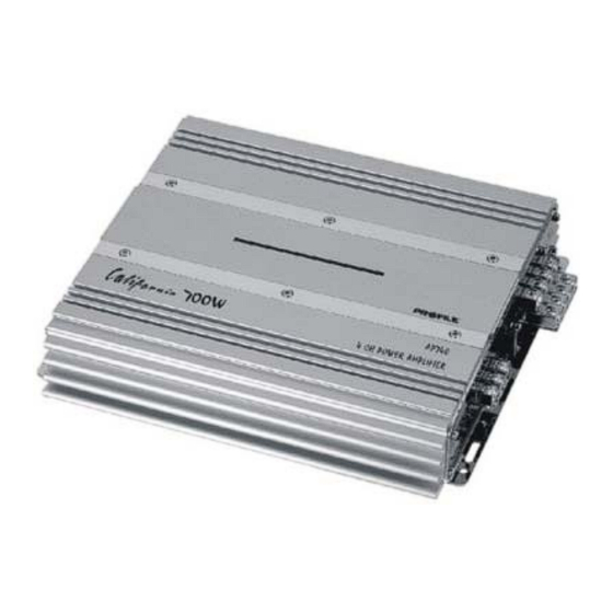
California AP400
Installation instructions & owner's manual
Profile California AP400 Installation Instructions & Owner's Manual
California mosfet power amplifiers
Hide thumbs
Also See for California AP400
:
Installation instructions and owner's manual
(20 pages)
1
2
3
4
5
6
7
8
9
10
11
12
13
14
15
16
17
18
19
20
Table Of Contents
21
page
of
21
Go
/
21
Contents
Table of Contents
Troubleshooting
Bookmarks
Table of Contents
Mosfet Power Amplifiers
Safety Precautions
Features and Benefits
Treble Boost
Subsonic Filter
DC Offset Protection
Short Circuit Protection
Thermal Protection
Protection Indicator
Power Connections
Mounting Location
Signal Connections
Speaker Connections
Setting the Gain
Troubleshooting the System
Specifications
Limited Warranty
Warranty Repair Policy
Advertisement
Quick Links
1
Mosfet Power Amplifiers
2
Features and Benefits
3
Power Connections
4
Signal Connections
5
Speaker Connections
6
Setting the Gain
7
Specifications
Download this manual
See also:
Installation Instructions & Owner's Manual
MOSFET POWER AMPLIFIERS
Installation Instructions / Owner's Manual
AP400
AP600
AP1000
AP1200
AP2000
AP740
AP1040
AP700M
AP1000M
Table of
Contents
Previous
Page
Next
Page
1
2
3
4
5
Advertisement
Table of Contents
Need help?
Do you have a question about the California AP400 and is the answer not in the manual?
Ask a question
Questions and answers
Related Manuals for Profile California AP400
Car Amplifier Profile California AP1000 Installation Instructions And Owner's Manual
Mosfet power amplifier (20 pages)
Amplifier Profile California AP2000 Installation Instructions & Owner's Manual
California mosfet power amplifiers (21 pages)
Amplifier Profile California AP1040 Installation Instructions & Owner's Manual
California mosfet power amplifiers (21 pages)
Amplifier Profile California AP600 Installation Instructions & Owner's Manual
California mosfet power amplifiers (21 pages)
Amplifier Profile California AP1200 Installation Instructions & Owner's Manual
California mosfet power amplifiers (21 pages)
Amplifier Profile California AP740 Installation Instructions & Owner's Manual
California mosfet power amplifiers (21 pages)
Amplifier Profile California 400SX Installation And Owner's Manual
Mosfet power amplifiers (20 pages)
Amplifier Profile California Mosfet 100SX Installation Instructions & Owner's Manual
Mosfet power amplifiers (21 pages)
Amplifier Profile Baja BA400 Installation Instructions Manual
Mosfet power amplifiers (20 pages)
Amplifier Profile Clarus CL440 Installation And Owner's Manual
Mosfet power amplifiers (21 pages)
Amplifier Profile California 400MSX Installation And Owner's Manual
Mosfet power amplifiers (17 pages)
Amplifier Profile J600.4 Owner's Manual
Mosfet power amplifiers california jam (20 pages)
This manual is also suitable for:
California ap600
California ap1000
California ap1200
California ap2000
California ap740
California ap1040
...
Show all
California ap700m
California ap1000m
Table of Contents
Save PDF
Print
Rename the bookmark
Delete bookmark?
Delete from my manuals?
Login
Sign In
OR
Sign in with Facebook
Sign in with Google
Upload manual
Upload from disk
Upload from URL


Need help?
Do you have a question about the California AP400 and is the answer not in the manual?
Questions and answers