Advertisement
Advertisement
Table of Contents

Related Manuals for Profile Baja BA400


Summary of Contents for Profile Baja BA400
-
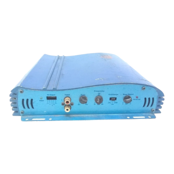
Page 1: Mosfet Power Amplifiers
MOSFET POWER AMPLIFIERS Installation Instructions / Owner's Manual BA400 BA440... - Page 2 It is recommended that you have our product installed by an authorized Profile retailer. However, if you decide to install it yourself, please carefully read through this manual and take your time to do a quality installation.
-
Page 3: Safety Precautions
AFETY PRECAUTIONS Fuse amplifier's power wire at the battery. Be sure to fuse the power wire within 12" of the car's battery. This will protect the car's battery in case of a short circuit between the power amplifier and battery. THIS IS A MUST, the amplifier's built-in fuse will only protect the power amplifier not the car's battery! Use high grade wire connectors. -
Page 4: Features And Benefits
EATURES AND BENEFITS DC Offset Protection This circuit protects the output of the amplifier against DC voltage. If for some reason DC voltage is detected at the output stage, the amplifier will shut down protecting the speakers from direct current. Short Circuit Protection The circuit protects the amplifier from damage due to a short found in the speakers or wiring. - Page 5 Bass Boost For added low frequency performance the amplifiers are equipped with a variable 0~12 dB bass boost @ 45Hz. (BA 400 only) Power Fusing This protects the amplifier against short circuits and excessive current. Remote Turn-on Automatically turns amplifier on when connected to the head unit's remote output. The amplifier will turn on and off with the head unit to save current consumption.
-
Page 6: Mounting Location
OUNTING LOCATION Before you start the installation, it will be necessary to find a mounting location for the amplifier. Find a location in which the amplifier will receive adequate ventilation in order to dissipate the heat it develops during operation. Two popular mounting locations are in the trunk or under the seat. -
Page 7: Power Connections
OWER CONNECTIONS RADIO'S REMOTE RADIO'S REMOTE TURN-ON OUTPUT TURN-ON OUTPUT 94.7 94.7 IMPORTANT! Before making any connections, disconnect the car's battery until the installation is completed to avoid possible damage to the electrical system. Connect the amplifier to the car's battery. At times, the amplifier will need to draw large levels of current that cannot be provided by any circuit in the car's fuse box. -
Page 8: Signal Connections
IGNAL CONNECTIONS Connect the RCA output of the head unit (AM/FM cassette player, CD, or DAT) to the RCA input terminals of the amplifier. To make these connections, we recommend high quality RCA cables, which are available at your local car audio retailer. Run signal wires away from electrical wires to avoid possibility of induced noise from the car's electrical system (i.e. - Page 9 IGH LEVEL CONNECTIONS (OPTIONAL) High Level inputs have been included to connect the amplifier to a radio without low-level outputs (i.e. factory radio). This connection will allow you to connect directly to the speaker output of the radio with out the need of an external adapter. Determine the type of radio you have and make one of the following connections.
- Page 10 FOUR CHANNEL CONNECTIONS: FLOATING GROUND RADIO (MOST COMMON TYPE)
- Page 11 PEAKER CONNECTIONS Make the speaker connections using speaker wire that is at least 14 gauge or heavier. As with any audio component, proper phasing of the amplifier and speakers is essential for strong bass response. When connecting, make sure that positive (+) from the amplifier is connected to the positive (+) of the speaker, and the same for negative (-).
-
Page 12: Speaker Connections
PEAKER CONNECTIONS (BRIDGED) The Baja amplifiers are capable of being bridged in a mono configuration. This feature allows you the flexibility of using the amplifier to drive a ** subwoofer or a center channel. In this configuration the amplifier sums the right and left channel to deliver one channel (mono) output. - Page 13 PEAKER CONNECTIONS (TRI-MODE) NON-POLAR NON-POLAR INDUCTOR INDUCTOR CAPACITOR CAPACITOR (COIL) (COIL) CAUTION! In Tri- mode operation, the amplifier must see a 2 Ohm load or higher for the stereo satellites and no lower than 4 Ohms for the subwoofer(s). Any lower than the above mentioned impedance will cause the amplifier to overheat and possibly cause permanent damage to the amplifier.
- Page 14 DJUSTING THE X-OVER AND BASS BOOST (Please note: If you intend to us e the amplifier in the Tri-mode configuration, it is necessary to set the crossover control to the "Flat" setting in order to receive full range output) The Baja amplifiers are equipped with a built-in variable crossover network allowing you to select the crossover type (i.e.
-
Page 15: Troubleshooting The System
ROUBLE SHOOTING THE SYSTEM We have put together this trouble-shooting guide if you experience problems after installing the amplifier. Please keep in mind that the majority of problems incurred are caused by improper installation and not the equipment itself. In addition, there are many components in the system that could cause various signal problems such as inducted electrical noise and engine noise. -
Page 16: Specifications
PECIFICATIONS Output Power @ 4 Ohm RMS Power @ 4 Ohm RMS Power @ 2 Ohm Bridged RMS @ 4 Ohm THD @ RMS Power Frequency Response 10Hz ~ 35Khz Signal To Noise Stereo Separation Low Level Input 200mV ~ 5V Load Impedance Stereo 2 ~ 8 Ohms Load Impedance Bridged... -
Page 17: Limited Warranty
One (1) Year from the date of sale to the original consumer purchaser. If this product is proven to be defective within this one year period, Profile will repair it when said product is returned, with a copy of the dated sales receipt, freight prepaid to Profile. -
Page 18: Warranty Repair Policy
4) Include a brief description of the problem or failure with the unit. 5) Include the return street address and daytime telephone number. 6) Allow 2~3 weeks for repair (this period includes shipping time). Send unit to : PROFILE CONSUMER ELECTRONICS, INC. 15060 SHOEMAKER AVE SANTA FE SPRINGS, CA 90670 TEL: 562-404-9393... - Page 19 PROFILE CONSUMER ELECTRONICS, INC. 15060 SHOEMAKER AVE SANTA FE SPRINGS, CA 90670 TEL: 562-404-9393 FAX: 562-404-9433 WWW.PROFILEUSA.COM...
Need help?
Do you have a question about the Baja BA400 and is the answer not in the manual?
Questions and answers