
Related Manuals for Accurate Technology Digi-Stop


Summary of Contents for Accurate Technology Digi-Stop
- Page 1 Digi-Stop™ User Manual for: Digi-Stop Digital Readout Firmware version d 2.000 & Higher...
- Page 2 Accurate Technology, Inc., warrants this product against defective parts and workmanship for 1 year commencing from the date of original purchase. Upon notification of a defect, Accurate Technology, Inc., shall have the option to repair or replace any defective part. Such services shall be the customer's sole and exclusive remedy.
-
Page 3: Table Of Contents
Table of Contents ............4 ECTION ENERAL NFORMATION Introduction....................4 What This Manual Includes................4 Digi-Stop Specifications................4 Digi-Stop Parts .................... 5 ............... 6 ECTION NSTALLATION Assembly & Mounting .................. 6 Calibration ....................7 Maintenance ....................7 Changing the Batteries ................8 The LCD Display.................. -
Page 4: Section 1 General Information
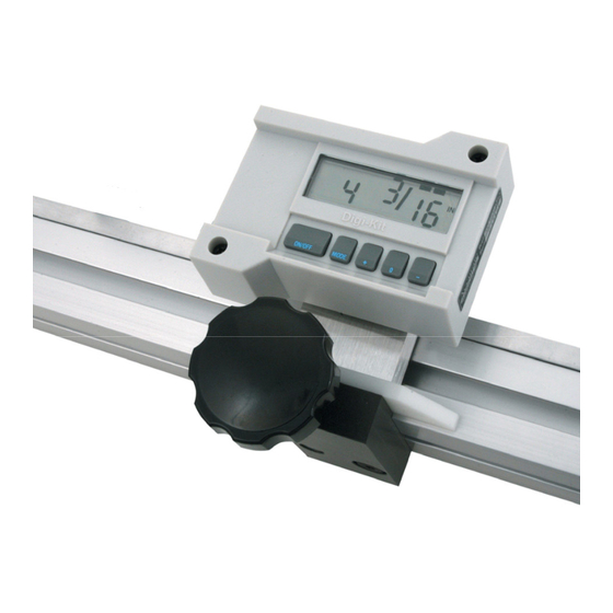
ENERAL NFORMATION Introduction Digi-Stop is a complete digital stop and fence system for chop saws, radial arm saws, and miter saws. It is the consumer model of Accurate Technology’s ProStop™ Stop & Fence System. The readout has easy-to-use front panel... -
Page 5: Digi-Stop Parts
Digi-Stop Parts Each Digi-Stop is shipped in two packages. The first contains the Fence extrusion with the Scale attached. The second package contains the Digital Stop and some installation hardware. Pictured below are parts that will be referred to throughout this manual. -
Page 6: Section 2 Installation
ECTION NSTALLATION Assembly & Mounting Digi-Stop is easy to install. By following the basics of good installation reliable, error-free operation can be expected. 1. Carefully slide the encoder onto the Scale. 2. Loosen the locking knob and slide the Stop assembly into the fence extrusion. -
Page 7: Calibration
Calibration Once installed, Digi-Stop can be calibrated easily and quickly. The following is an example of calibrating Digi-Stop on a cutoff saw application. Other installations follow the same general procedure. Cut a small part (approximately 8 inches) using the stop. DO NOT MOVE THE STOP UNTIL THIS PROCEDURE IS COMPLETED. -
Page 8: Changing The Batteries
IN PLACE WHEN THE CASE HALVES ARE SCREWED TOGETHER. The LCD Display The above figure illustrates all the segments available on the LCD. (Not all segments are used on Digi-Stop Systems) Pressing and holding the key for 10 seconds with power off... -
Page 9: Section 3 Operation
PERATION Readout Keys Key Timing The keys pictured above, are found on all Digi-Stop readouts, and some of them have multiple functions. Timing, which is how long a key is depressed, and the combination of the keys pressed is important. This manual uses the term ‘”momentarily” to describe a key press of shorter than 1 second. -
Page 10: Datum, And
illuminated bar indicates an additional 1/64 of an inch of measurement.) For better resolution, switch to 1/32 or 1/64 mode. For the best resolution and accuracy switch to a decimal mode – inches or millimeters.. When the measurement is greater than 99 63/64 inches, a +100 +100 +100 and/or +200 +100... -
Page 11: Readout Resolution
The incremental mode allows the operator to make relative distance measurements from one arbitrary point to another. The absolute position of the Digi-Stop is not lost when using the incremental mode. Absolute The readout automatically enters ABS mode when power is first applied. -
Page 12: Circuit Board Jumpers
UNITS longer functions to change the measurement units displayed. The absolute position of the Digi-Stop is not lost when using the incremental mode. When the readout is switched back to the absolute mode the readout reflests the current stop position relative to your original calibrated absolute setting. -
Page 13: Readout Programming
Readout Programming Several functions of the Digi-Stop readout is user programmable. following describes what features and functions are available and how to change the factory defaults to customize your Digi-Stop system.. To enter Programming Mode: 1. Press and hold the key then momentarily press the key. -
Page 14: Programming Parameters
Programming Parameters The Digi-Stop readout programming parameters are listed below. Values in [ ] are the available range of values that can be entered for that parameter. Factory defaults are shown in Bold Red. Pr 1 – Datum Key to + 999.999in] or to +9999.99mm]... -
Page 15: Frequently Asked Questions
These clips are designed to expand when the two case halves are screwed together. The readings are “backwards”? You can change reading direction of the Digi-Stop by changing the value of Programming Parameter Pr 2. Accurate Technology DigiStop... - Page 16 Fletcher, NC 28732 USA 828.654.7920 Please register your product at: http://www.digi-kit.com/registration.htm This manual is available online at: www.digi-kit.com Manual P/N 800-1070-001 Rev G. Copyright © © © © Accurate Technology 2008 Manual Part # 800-1070-001, Rev G, 10-2008 Page 16 of 16...
Need help?
Do you have a question about the Digi-Stop and is the answer not in the manual?
Questions and answers