
Related Manuals for Yamaha Majesty YP400Y


Summary of Contents for Yamaha Majesty YP400Y
- Page 1 Read this manual carefully before operating this vehicle. OWNER’S MANUAL YP400Y LIT-11626-22-28 34B-28199-10...
- Page 2 EAU10042 Read this manual carefully before operating this vehicle. This manual should stay with this vehicle if it is sold.
- Page 3 Yamaha has met these standards without reducing the performance or economy of operation of the scooter. To maintain these high standards, it is important that you and your Yamaha dealer pay close attention to the rec- ommended maintenance schedules and operating instructions contained within this manual.
-
Page 4: Important Manual Information
IMPORTANT MANUAL INFORMATION EAU10132 Particularly important information is distinguished in this manual by the following notations: This is the safety alert symbol. It is used to alert you to potential personal injury hazards. Obey all safety messages that follow this symbol to avoid possible injury or death. - Page 5 IMPORTANT MANUAL INFORMATION EAU10193 YP400Y OWNER’S MANUAL ©2008 by Yamaha Motor Corporation, U.S.A. 1st edition, May 2008 All rights reserved. Any reprinting or unauthorized use without the written permission of Yamaha Motor Corporation, U.S.A. is expressly prohibited. Printed in Japan.
-
Page 6: Table Of Contents
TABLE OF CONTENTS LOCATION OF IMPORTANT Ignition circuit cut-off system ..4-17 Air filter elements and check LABELS ..........1-1 hoses and V-belt case air filter FOR YOUR SAFETY – element ........7-20 SAFETY INFORMATION ....2-1 PRE-OPERATION CHECKS ....5-1 Checking the throttle cable free Further safe-riding points ....2-5 Pre-operation check list .... - Page 7 Matte color caution ......8-1 Care ..........8-1 Storage ..........8-3 SPECIFICATIONS ......9-1 CONSUMER INFORMATION....10-1 Identification numbers ....10-1 Reporting safety defects ....10-3 Scooter noise regulation ....10-4 Maintenance record .......10-5 YAMAHA MOTOR CORPORATION, U.S.A. STREET AND ENDURO MOTORCYCLE LIMITED WARRANTY .......10-7 YAMAHA EXTENDED SERVICE (Y.E.S.) ........10-9...
-
Page 8: Location Of Important Labels
Read and understand all of the labels on your vehicle. They contain important information for safe and proper operation of your vehicle. Never remove any labels from your vehicle. If a label becomes difficult to read or comes off, a replacement label is available from your Yamaha dealer. - Page 9 LOCATION OF IMPORTANT LABELS NOTICE Cleaning with alkaline or acid cleaner, gasoline or solvent will damage windshield. Use neutral detergent. 8ET — 2815K — 00 WARNING BEFORE YOU OPERATE THIS VEHICLE, READ 5RU-21668-00 THE OWNER’S MANUAL AND ALL LABELS. ALWAYS WEAR AN APPROVED MOTORCYCLE HELMET, eye protection, and protective clothing.
- Page 10 LOCATION OF IMPORTANT LABELS 5RU - 21686 - 00...
-
Page 11: Safety Information
SAFETY INFORMATION EAU10263 time you use the vehicle to make sure it motorist’s blind spot. is in safe operating condition. Failure to Many accidents involve inexperi- Be a Responsible Owner inspect or maintain the vehicle properly enced operators. In fact, many op- As the vehicle’s owner, you are respon- increases the possibility of an accident erators who have been involved in... - Page 12 SAFETY INFORMATION ed by road and traffic conditions. accidents are the result of head inju- monoxide, a deadly gas. Breathing car- Always signal before turning or ries. The use of a safety helmet is the bon monoxide can cause headaches, changing lanes.
- Page 13 Yamaha accessories, which are avail- Loading sible and make sure to distribute able only from a Yamaha dealer, have Adding accessories or cargo to your the weight as evenly as possible been designed, tested, and approved...
-
Page 14: Specifications
SAFETY INFORMATION or others. Installing aftermarket prod- lightweight as possible and Aftermarket Tires and Rims ucts or having other modifications per- should be kept to a minimum. The tires and rims that came with your formed to your vehicle that change any Bulky or large accessories may scooter were designed to match the of the vehicle’s design or operation... -
Page 15: Further Safe-Riding Points
SAFETY INFORMATION EAU10371 and ankle so they do not flap), and Further safe-riding points a bright colored jacket. Be sure to signal clearly when Do not carry too much luggage on making turns. the scooter. An overloaded scoot- Braking can be extremely difficult er is unstable. -
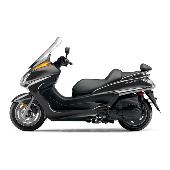
Page 16: Description
DESCRIPTION EAU10410 Left view 1. Headlight (page 7-34) 9. Air filter element (left) (page 7-20) 2. Fuel tank cap (page 4-9) 10. Engine oil filter element (page 7-14) 3. Rear storage compartment (page 4-14) 11. Sidestand (page 4-16, 7-30) 4. V-belt case air filter element (page 7-20) 5. -
Page 17: Right View
DESCRIPTION EAU10420 Right view 1. Grab bar (page 6-2) 2. Passenger seat (page 4-12) 3. Rider seat (page 4-12) 4. Coolant reservoir (page 7-18) 5. Radiator 6. Centerstand (page 7-30) 7. Air filter element (right) (page 7-20) 8. Shock absorber assembly spring preload adjusting ring (page 4-16) -
Page 18: Controls And Instruments
DESCRIPTION EAU10430 Controls and instruments 1. Rear brake lever (page 4-8) 9. Throttle grip (page 7-22) 2. Left handlebar switches (page 4-7) 10. Front storage compartment B (page 4-14) 3. Rear brake lock lever (page 4-8) 11. Main switch/steering lock (page 4-1) 4. -
Page 19: Instrument And Control Functions
INSTRUMENT AND CONTROL FUNCTIONS EAU10460 sidestand is moved down. To unlock the steering Main switch/steering lock Push the key in, and then turn it to “OFF” while still pushing it. EAU10661 All electrical systems are off. The key can be removed. EWA10061 WARNING Never turn the key to “OFF”... -
Page 20: Indicator And Warning Lights
This warning light comes on if a prob- lem is detected in the electrical circuit monitoring the engine. If this occurs, have a Yamaha dealer check the self-diagnosis system. The electrical circuit of the warning light can be checked by turning the key to “ON”. -
Page 21: Tachometer
INSTRUMENT AND CONTROL FUNCTIONS EAU11872 EAU36106 Tachometer Multi-function display EWA12312 WARNING Be sure to stop the vehicle before making any setting changes to the multi-function display. Changing settings while riding can distract the operator and increase the risk of an accident. - Page 22 INSTRUMENT AND CONTROL FUNCTIONS cator started flashing) tor will start flashing, and the display will the fuel reserve tripmeter manually, it a self-diagnosis device automatically change to the fuel re- will reset itself automatically and the a clock serve tripmeter mode “TRIP F” and display will return to the prior mode af- an ambient temperature display start counting the distance traveled...
- Page 23 If the multi-function display indicates such an error code, note the code num- The oil change indicator may flash ber, and then have a Yamaha dealer Oil change indicator “OIL” when the engine is revved with the check the vehicle.
- Page 24 INSTRUMENT AND CONTROL FUNCTIONS the minute digits will start flashing. will not be displayed. 4. Push the “RESET” button to set The accuracy of the temperature the minutes. reading may be affected when 5. Push the “SELECT” button and riding slowly (approximately under then release it to start the clock.
-
Page 25: Handlebar Switches
INSTRUMENT AND CONTROL FUNCTIONS EAU12347 Right EAU12500 Handlebar switches Horn switch “ ” Press this switch to sound the horn. Left EAU12660 Engine stop switch “ ” Set this switch to “ ” before starting the engine. Set this switch to “ ”... -
Page 26: Front Brake Lever
INSTRUMENT AND CONTROL FUNCTIONS EAU12900 EAU12950 EAU12962 Front brake lever Rear brake lever Rear brake lock lever 1. Front brake lever 1. Rear brake lever 1. Rear brake lock lever The front brake lever is located on the The rear brake lever is located on the This vehicle is equipped with a rear right handlebar grip. -
Page 27: Fuel Tank Cap
INSTRUMENT AND CONTROL FUNCTIONS rear brake lock lever is applied. EAU13163 Fuel tank cap To provide secure locking of the rear wheel, apply the rear brake le- To open the fuel tank cap ver first before moving the rear 1. Open the lid by sliding the lever brake lock lever to the left. -
Page 28: Fuel
INSTRUMENT AND CONTROL FUNCTIONS move it. EAU13212 Fuel 3. Close the lid. Make sure there is sufficient gasoline in EWA11121 WARNING the tank. EWA10881 Be sure that the fuel tank cap is WARNING properly installed and locked before Gasoline and gasoline vapors are riding the scooter. -
Page 29: Catalytic Converter
Do not allow the engine to idle Your Yamaha engine has been de- more than a few minutes. Long signed to use regular unleaded gaso- idling can cause a build-up of line with a pump octane number heat. -
Page 30: Seats
INSTRUMENT AND CONTROL FUNCTIONS pairable damage to the catalytic EAU34140 Seats converter. 1. Open. 1. Rider seat 2. Passenger seat Do not push inward when turning the key. Rider seat 3. Fold the rider seat up. To open the rider seat 1. -
Page 31: Adjusting The Rider Seat
INSTRUMENT AND CONTROL FUNCTIONS To close the rider seat To install the passenger seat EAU34150 Adjusting the rider seat 1. Fold the rider seat down, and then 1. Insert the projections on the pas- push it down to lock it in place. senger seat into the holders as 2. -
Page 32: Storage Compartments
INSTRUMENT AND CONTROL FUNCTIONS EAU14493 and then remove it. Storage compartments Front storage compartment A To open the storage compartment when it is locked, insert the key in the lock, turn it counterclockwise, and then grasp the lock while pushing the button To open the storage compartment when it is unlocked, simply grasp the 1. - Page 33 INSTRUMENT AND CONTROL FUNCTIONS being washed, wrap any articles stored in the compartment in a plastic bag. Do not keep anything valuable or breakable in the storage com- partment. ECA11100 NOTICE Do not leave the rider seat open for an extended period of time, other- 1.
-
Page 34: Adjusting The Shock Absorber Assemblies
EWA10210 sibility of raising the sidestand be- WARNING fore starting off. Therefore, check Always adjust both shock absorber this system regularly as described assemblies equally, otherwise poor below and have a Yamaha dealer re- 4-16... -
Page 35: Ignition Circuit Cut-Off System
INSTRUMENT AND CONTROL FUNCTIONS pair it if it does not function proper- EAU15373 Ignition circuit cut-off system The ignition circuit cut-off system (com- prising the sidestand switch and brake light switches) has the following func- tions. It prevents starting when the side- stand is up, but neither brake is ap- plied. - Page 36 2. Make sure that the engine stop switch is turned on. stand during this inspection. • 3. Turn the key on. If a malfunction is noted, have a Yamaha 4. Keep the front or rear brake applied. dealer check the system before riding. 5. Push the start switch.
-
Page 37: For Your Safety - Pre-Operation Checks
Failure to inspect or maintain the vehicle properly increases the possibility of an accident or equipment damage. Do not operate the vehicle if you find any problem. If a problem cannot be corrected by the procedures provided in this manual, have the vehicle inspected by a Yamaha dealer. Before using this vehicle, check the following points:... -
Page 38: Pre-Operation Check List
If necessary, add recommended brake fluid to specified level. Check hydraulic system for leakage. Make sure that operation is smooth. Check cable free play. Throttle grip 7-22, 7-29 If necessary, have Yamaha dealer adjust cable free play and lubricate cable and grip housing. - Page 39 Make sure that all nuts, bolts and screws are properly tightened. Chassis fasteners — Tighten if necessary. Instruments, lights, signals Check operation. — and switches Correct if necessary. Check operation of ignition circuit cut-off system. Sidestand switch 4-16 If system is not working correctly, have Yamaha dealer check vehicle.
-
Page 40: Operation And Important Riding Points
Yamaha dealer. a turnover. To start the engine after a hicle for the first time. -
Page 41: Starting Off
OPERATION AND IMPORTANT RIDING POINTS EAU16761 EAU16780 EAU16793 Starting off Acceleration and deceleration Braking EWA10300 WARNING Before starting off, allow the engine to Avoid braking hard or suddenly warm up. (especially when leaning over to 1. While pulling the rear brake lever one side), otherwise the scooter with your left hand and holding the may skid or overturn. -
Page 42: Engine Break-In
1600 km (1000 mi). The various parts in period, immediately have a the engine wear and polish themselves Yamaha dealer check the vehi- Rear to the correct operating clearances. cle. During this period, prolonged full-throt-... -
Page 43: Parking
OPERATION AND IMPORTANT RIDING POINTS EAU17213 Parking When parking, stop the engine, and then remove the key from the main switch. EWA10311 WARNING Since the engine and exhaust system can become very hot, park in a place where pedestri- ans or children are not likely to touch them and be burned. -
Page 44: Periodic Maintenance And Adjustment
(if applicable). Yamaha dy or wet conditions, the air filter el- your risk of injury or death during dealers are trained and equipped to... -
Page 45: Owner's Tool Kit
Owner’s tool kit If you do not have the tools or experi- ence required for a particular job, have a Yamaha dealer perform it for you. 1. Storage compartment mat 2. Owner’s tool kit The owner’s tool kit is located inside the... -
Page 46: Periodic Maintenance Chart For The Emission Control System
Replace if necessary. Check the air cut-off valve, reed √ 7 * Air induction system valve, and hose for damage. Replace any damaged parts. * Since these items require special tools, data and technical skills, have a Yamaha dealer perform the service. -
Page 47: General Maintenance And Lubrication Chart
PERIODIC MAINTENANCE AND ADJUSTMENT EAU32185 General maintenance and lubrication chart INITIAL ODOMETER READINGS 600 mi 4000 mi 8000 mi 12000 mi 16000 mi 20000 mi ITEM ROUTINE (1000 km) (7000 km) (13000 km) (19000 km) (25000 km) (31000 km) 1 month 6 months 12 months 18 months... - Page 48 PERIODIC MAINTENANCE AND ADJUSTMENT INITIAL ODOMETER READINGS 600 mi 4000 mi 8000 mi 12000 mi 16000 mi 20000 mi ITEM ROUTINE (1000 km) (7000 km) (13000 km) (19000 km) (25000 km) (31000 km) 1 month 6 months 12 months 18 months 24 months 30 months Check bearing assemblies for...
- Page 49 Adjust headlight beam. * Since these items require special tools, data and technical skills, have a Yamaha dealer perform the service. From 24000 mi (37000 km) or 36 months, repeat the maintenance intervals starting from 8000 mi (13000 km) or 12 months.
- Page 50 PERIODIC MAINTENANCE AND ADJUSTMENT EAU36370 The air filters and V-belt filter need more frequent service if you are riding in unusually wet or dusty areas. Hydraulic brake service After disassembling the brake master cylinders and calipers, always change the fluid. Regularly check the brake fluid levels and fill the reservoirs as required.
-
Page 51: Removing And Installing Cowlings And Panels
PERIODIC MAINTENANCE AND ADJUSTMENT EAU18712 Removing and installing cowlings and panels The cowlings and panels shown need to be removed to perform some of the maintenance jobs described in this chapter. Refer to this section each time a cowling or panel needs to be re- moved and installed. - Page 52 PERIODIC MAINTENANCE AND ADJUSTMENT Cowling B To install the cowling Place the cowling in the original posi- To remove the cowling tion, and then install the screws. 1. Remove the screws. Cowlings C and D To remove one of the cowlings 1.
- Page 53 PERIODIC MAINTENANCE AND ADJUSTMENT 2. Install the screw access cover by 1. Left floorboard mat 1. Cowling E placing it in its original position. 2. Remove the cowling screws. To install the cowling 3. Install the grab bar by installing the 1.
- Page 54 PERIODIC MAINTENANCE AND ADJUSTMENT EAU34290 To install the panel Place the panel in the original position, Panel A and then install the bolts. To remove the panel 1. Remove the bolts. 1. Panel B 2. Screw To install the panel Panel B Place the panel in the original position, and then install the screws.
-
Page 55: Checking The Spark Plug
If the spark plug shows a distinctly dif- ferent color, the engine could be oper- ating improperly. Do not attempt to diagnose such problems yourself. In- stead, have a Yamaha dealer check the vehicle. 1. Spark plug cap 2. Check the spark plug for electrode 4. - Page 56 PERIODIC MAINTENANCE AND ADJUSTMENT necessary. 3. Install the spark plug with the spark plug wrench, and then tight- Specified spark plug: en it to the specified torque. NGK/CR7E Tightening torque: Spark plug: To install the spark plug 12.5 Nm (1.25 m·kgf, 9 ft·lbf) 1.
-
Page 57: Canister
PERIODIC MAINTENANCE AND ADJUSTMENT EAU36110 EAU34184 Canister Engine oil and oil filter element The engine oil level should be checked before each ride. In addition, the oil must be changed and the oil filter ele- ment replaced at the intervals specified in the periodic maintenance and lubri- cation chart and when the oil change in- dicator comes on. - Page 58 PERIODIC MAINTENANCE AND ADJUSTMENT to collect the used oil. 3. Remove the engine oil filler cap and the engine oil drain bolt to drain the oil from the crankcase. 1. Engine oil drain bolt 1. Bolt 2. Washer 2. Oil filter element cover 6.
-
Page 59: Reset Oil Change Indicator
PERIODIC MAINTENANCE AND ADJUSTMENT 7. Install the compression spring and Recommended engine oil: oil filter element cover by installing See page 9-1. the bolts, then tightening them to Oil quantity: the specified torque. Without oil filter element replace- ment: Tightening torque: 1.50 L (1.59 US qt, 1.32 Imp.qt) Oil filter element cover bolt: With oil filter element replacement:... -
Page 60: Final Transmission Oil
The final transmission case must be checked for oil leakage before each ride. If any leakage is found, have a Yamaha dealer check and repair the scooter. In addition, the final transmis- sion oil must be changed as follows at the intervals specified in the periodic maintenance and lubrication chart. -
Page 61: Coolant
PERIODIC MAINTENANCE AND ADJUSTMENT EAU20070 Recommended final transmission Coolant oil: The coolant level should be checked See page 9-1. before each ride. In addition, the cool- Oil quantity: ant must be changed at the intervals 0.25 L (0.26 US qt, 0.22 Imp.qt) specified in the periodic maintenance 7. - Page 62 If water has been 1. Screw added to the coolant, have a 2. Coolant reservoir cover Yamaha dealer check the anti- 4. Check the coolant level in the cool- freeze content of the coolant as ant reservoir. soon as possible, otherwise the...
-
Page 63: Air Filter Elements And Check Hoses And V-Belt Case Air Filter Element
PERIODIC MAINTENANCE AND ADJUSTMENT EAU34205 Left Left Air filter elements and check hoses and V-belt case air filter element The air filter elements and the V-belt case air filter element should be ser- viced at the intervals specified in the periodic maintenance and lubrication chart. - Page 64 PERIODIC MAINTENANCE AND ADJUSTMENT NOTICE: Make sure that each Left Cleaning the V-belt case air filter el- filter element properly ement seated in its case. Always re- 1. Remove cowling (See place both air filter elements page 7-8.) at the same time, otherwise 2.
-
Page 65: Checking The Throttle Cable Free Play
3.0–5.0 mm (0.12–0.20 in) at the throttle grip. Periodically check the throttle cable free play and, if neces- sary, have a Yamaha dealer adjust it. 7. Check the V-belt case air filter ele- ment for damage and replace it if... -
Page 66: Valve Clearance
Rear: from occurring, the valve clearance specified tires. 250 kPa (2.50 kgf/cm , 36 psi) must be adjusted by a Yamaha dealer 90–196 kg (198–432 lb): at the intervals specified in the periodic Tire air pressure Front: maintenance and lubrication chart. - Page 67 It is dangerous to ride with a ed wheel parts replacement should The tires must be checked before each worn-out tire. When a tire tread be left to a Yamaha Service Techni- ride. If a tire tread shows crosswise begins to show crosswise lines, cian.
-
Page 68: Cast Wheels
The wheel rims should be checked for cracks, bends, warpage or damage before each ride. If any damage is found, have a Yamaha dealer replace the wheel. Do not 1. Valve stem nut attempt even the smallest repair to 2. -
Page 69: Adjusting The Rear Brake Lock Lever Cable
To decrease the rear brake lock lever Adjusting the rear brake lock brake lever ends. If there is free play, cable length, turn the adjusting nut in lever cable have a Yamaha dealer inspect the direction (b). brake system. EWA10650 WARNING... -
Page 70: Checking The Front And Rear Brake Pads
EAU22580 Checking the front and rear Checking the brake fluid level peared, have a Yamaha dealer replace brake pads the brake pads as a set. Front brake The front and rear brake pads must be... -
Page 71: Changing The Brake Fluid
Changing the brake fluid ing it to become ineffective. lower the boiling point of the fluid Have a Yamaha dealer change the Before riding, check that the brake fluid and may result in vapor lock. brake fluid at the intervals specified in... -
Page 72: Checking And Lubricating The Cables
If a cable is damaged maintenance chart. or does not move smoothly, have a Yamaha dealer check or replace it. WARNING! Damage to the outer housing of cables may result in in- ternal rusting and cause interfer- The pivoting points of the front and rear ence with cable movement. -
Page 73: Checking And Lubricating The Centerstand And Sidestand
Yamaha dealer check or re- tenance and lubrication chart. pair it. Otherwise, the centerstand or sidestand could contact the ground... -
Page 74: Checking The Steering
[EWA10751] fork does not operate smoothly, 2. Hold the lower ends of the front have a Yamaha dealer check or re- fork legs and try to move them for- pair it. ward and backward. If any free play can be felt, have a Yamaha dealer check or repair the steering. -
Page 75: Battery
ECA10631 Electrolyte is poisonous and To charge the battery NOTICE dangerous since it contains sul- Have a Yamaha dealer charge the bat- Always keep battery furic acid, which causes severe tery as soon as possible if it seems to charged. -
Page 76: Replacing The Fuses
2. Remove the blown fuse, and then have a Yamaha dealer charge install a new fuse of the specified 1. Spare main fuse your battery. -
Page 77: Replacing A Headlight Bulb
This model is equipped with quartz bulb 40.0 A headlights. If a headlight bulb burns Ignition fuse: 10.0 A out, have a Yamaha dealer replace it Signaling system fuse: and, if necessary, adjust the headlight 10.0 A beam. Headlight fuse: 20.0 A... -
Page 78: Tail/Brake Light
LED-type tail/brake light. 1. Place the scooter on the center- If the tail/brake light does not come on, stand. have a Yamaha dealer check it. 2. Remove panel A. (See page 7-8.) 3. Remove the windshield by remov- ing the screws. -
Page 79: Replacing A Rear Turn Signal Light Bulb
PERIODIC MAINTENANCE AND ADJUSTMENT clockwise. EAU34262 push it in, and then turn it clock- Replacing a rear turn signal 7. Insert a new bulb into the socket, wise until it stops. light bulb push it in, and then turn it clock- 6. -
Page 80: Replacing The License Plate Light Bulb
5. Insert a new bulb into the socket, self. However, should your scooter re- push it in, and then turn it clock- quire any repair, take it to a Yamaha wise until it stops. dealer, whose skilled technicians have 6. Install the license plate light lens... - Page 81 PERIODIC MAINTENANCE AND ADJUSTMENT heaters or furnaces. Gasoline or gasoline vapors can ignite or ex- plode, causing severe injury or property damage. 7-38...
-
Page 82: Troubleshooting Charts
Remove the spark plug and check the electrodes. The engine does not start. Have a Yamaha dealer check the vehicle. Check the battery. 4. Battery The engine turns over The battery is good. - Page 83 Start the engine. If the engine overheats again, have a The coolant level Yamaha dealer check and repair the cooling system. is OK. If coolant is not available, tap water can be temporarily used instead, provided that it is changed to the recommended coolant as soon as possible.
-
Page 84: Scooter Care And Storage
Be Rust and corrosion can develop even if ECA10781 NOTICE sure to consult a Yamaha dealer for high-quality components are used. A advice on what products to use be- rusty exhaust pipe may go unnoticed Avoid using strong acidic wheel fore cleaning the vehicle. - Page 85 SCOOTER CARE AND STORAGE cleaning products, solvent or After normal use on all metal, including chrome- and thinner, fuel (gasoline), rust re- Remove dirt with warm water, a mild nickel-plated, surfaces to prevent movers or inhibitors, brake flu- detergent, and a soft, clean sponge, corrosion.
-
Page 86: Storage
2. Fill up the fuel tank and add fuel [EWA10951] 4. Lubricate all control cables and the Consult a Yamaha dealer for advice on stabilizer (if available) to prevent pivoting points of all levers and what products to use. - Page 87 SCOOTER CARE AND STORAGE pedals as well as of the sidestand/ centerstand. 5. Check and, if necessary, correct the tire air pressure, and then lift the scooter so that both of its wheels are off the ground. Alterna- tively, turn the wheels a little every month in order to prevent the tires from becoming degraded in one spot.
-
Page 88: Specifications
SPECIFICATIONS EAU2633P Lubrication system: Radiator capacity (including all routes): Wet sump 1.57 L (1.66 US qt, 1.38 Imp.qt) Engine oil: Air filter: Dimensions: Type: Air filter element: Overall length: YAMALUBE 4 10W-40 or 20W-50, SAE Oil-coated paper element 2230 mm (87.8 in) 10W-40 or 20W-50 Fuel: Overall width:... - Page 89 SPECIFICATIONS Operation: Tire air pressure (measured on cold Rear brake: Centrifugal automatic type tires): Type: Chassis: Single disc brake Loading condition: Frame type: Operation: 0–90 kg (0–198 lb) Aluminum die-cast and steel tube back- Left hand operation Front: bone Recommended fluid: 200 kPa (2.00 kgf/cm , 29 psi) Caster angle:...
- Page 90 SPECIFICATIONS Headlight: Radiator fan fuse: 10.0 A Bulb type: Fuel injection system fuse: Halogen bulb Bulb voltage, wattage × quantity: 10.0 A Backup fuse: Headlight: 10.0 A 12 V, 60 W/55.0 W × 2 Tail/brake light: Front turn signal/position light: 12 V, 21 W/5.0 W ×...
-
Page 91: Consumer Information
Record the key identification number, vehicle identification number and mod- el label information in the spaces pro- vided below for assistance when ordering spare parts from a Yamaha dealer or for reference in case the vehi- cle is stolen. KEY IDENTIFICATION NUMBER: 1. - Page 92 The model label is affixed to the inside of the rear storage compartment. (See page 4-14.) Record the information on this label in the space provided. This in- formation will be needed when ordering spare parts from a Yamaha dealer. 10-2...
-
Page 93: Reporting Safety Defects
If you believe that your vehicle has a defect which could cause a crash or could cause injury or death, you should immediately inform the National Highway Traffic Safety Administration (NHTSA) in addition to notifying Yamaha Motor Corporation, U.S.A. If NHTSA receives similar complaints, it may open an investigation, and if it finds that a safety defect exists in a group of vehicles, it may order a recall and remedy campaign. -
Page 94: Scooter Noise Regulation
CONSUMER INFORMATION EAU26580 Scooter noise regulation TAMPERING WITH NOISE CONTROL SYSTEM PROHIBITED: Federal law prohibits the following acts or the causing thereof: (1) The removal or rendering inoperative by any person other than for purposes of maintenance, repair, or replacement of any device or element of design incorporated into any new ve- hicle for the purpose of noise control prior to its sale or delivery to the ultimate purchaser or while it is in use or (2) the use of the vehicle after such device or element of design has been removed or rendered inoperative by any person. -
Page 95: Maintenance Record
CONSUMER INFORMATION EAU26632 Maintenance record Copies of work orders and/or receipts for parts purchased and installed on your vehicle will be required to document that maintenance has been completed in accordance with the emissions warranty. The chart below is printed only as a reminder that maintenance work is required. - Page 96 CONSUMER INFORMATION Maintenance Date of Servicing dealer Mileage Remarks interval service name and address 32000 mi (49000 km) or 48 months 36000 mi (55000 km) or 54 months 40000 mi (61000 km) or 60 months 10-6...
-
Page 97: Yamaha Motor Corporation, U.s.a. Street And Enduro Motorcycle Limited Warranty
CONSUMER INFORMATION EAU26663 YAMAHA MOTOR CORPORATION, U.S.A. STREET AND ENDURO MOTORCYCLE LIMITED WARRANTY Yamaha Motor Corporation, U.S.A. hereby warrants that CUSTOMER’S RESPONSIBILITY under this Engine new Yamaha motorcycles will be free from defects in warranty shall be to: Displacement Period... - Page 98 CUSTOMER SERVICE What costs are my responsibility during the warranty period? If your machine requires warranty service, you must take it to any authorized Yamaha The customer’s responsibility includes all costs of normal maintenance services, motorcycle dealer within the continental United States. Be sure to bring your warranty non-warranty repairs, accident and collision damages, and oil, oil filters, air filters, registration card or other valid proof of the original date of purchase.
-
Page 99: Yamaha Extended Service (Y.e.s.)
This excellent Y.E.S. plan coverage is only available to dealer to see how comforting uninterrupted factory- Yamaha owners like you, and only while your Yamaha is still backed protection can be. within the Yamaha Limited Warranty period. So visit your authorized Yamaha dealer to get all the facts. - Page 100 Yamaha Limited Warranty expires. A special note: If visiting your dealer isn’t convenient, contact Yamaha with your Primary ID number (your frame number). We’ll be happy to help you get the Y.E.S. coverage you need.
- Page 101 INDEX Fuel ............4-10 Rear brake lock lever cable, adjusting ..7-26 Fuel tank cap..........4-9 Rider seat, adjusting ....... 4-13 Acceleration and deceleration ....6-2 Fuses, replacing ........7-33 Air filter elements and check hoses and V-belt case air filter element....7-20 Safe-riding points ........
- Page 102 INDEX Vehicle identification number ....10-1 Warranty, extended......... 10-9 Warranty, limited ........10-7 Wheel bearings, checking....... 7-31 Wheels ............ 7-25...
- Page 104 YAMAHA MOTOR CO., LTD. PRINTED ON RECYCLED PAPER PRINTED IN JAPAN 2008.5–0.6×1 !
Need help?
Do you have a question about the Majesty YP400Y and is the answer not in the manual?
Questions and answers
Replacement fuel pump assembly