Table of Contents
Advertisement
SETUP & OPERATION MANUAL
FEATURES
Optimum sanding results without the need
for special operator skills.
High quality conveyor belt for long service
life.
Variable feed rate from 3-20 FPM.
Conveyor motor equipped with indepen-
dant safety switch with removable key.
Magnetic safety switch on main motor.
Side and rear extension tables for easier
stock handling.
Reinforced pressure roller brackets.
Large metal hand wheel controls sanding
head height for thickness adjustment.
Internal dust shroud for efficient dust con-
trol.
Totally enclosed stand with storage com-
partment.
Ability to sand up to 30"material in two
passes. (Finish sanding may be required)
SPECIFICATIONS
MAXIMUM SANDING WIDTH
15" (380 MM) / *30" (*IN 2 PASSES)
MIN / MAX SANDING THICKNESS
1/4" (6 MM) / 4" (102 MM)
MINIMUM SANDING LENGTH
5" (127 MM)
FEED RATE
3 TO 20 FPM - VARIABLE
SANDING BELT SIZE
15" X 39 1⁄2" (381 X 1003 MM)
CONTACT ROLLER DIAMETER
2 1⁄2" (82 MM)
OVERALL DIMENSIONS (L X W X H)
WITH TABLES FULLY EXTENDED
39" X 52" X 64 1⁄2"
(991 X 1321 X 1638 MM)
CONVEYOR MOTOR
1⁄6 HP
MAIN MOTOR
3 HP , 220 V, 1 PH, 1720 RPM
WEIGHT
400 LBS / 182 KG
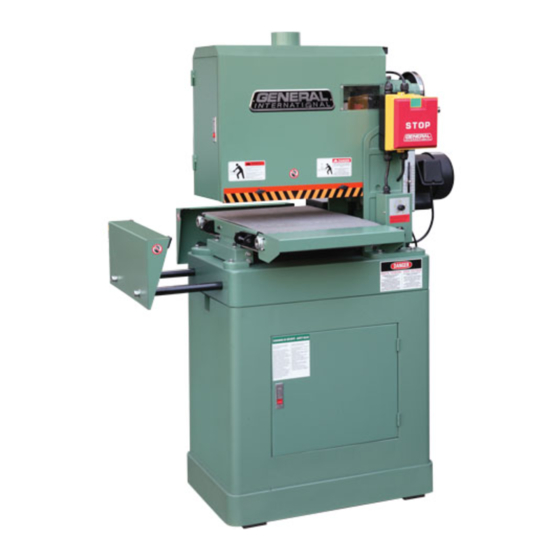
15" OPEN TYPE WIDE BELT SANDER
MODEL
# 15-030 M1
REVISION 1 - September 25/08
© Copyright General® International 09/2008
Advertisement
Table of Contents

Subscribe to Our Youtube Channel
Related Manuals for General International 15-030 M1


Summary of Contents for General International 15-030 M1
-
Page 1: Specifications
WITH TABLES FULLY EXTENDED MODEL 39” X 52” X 64 1⁄2” (991 X 1321 X 1638 MM) CONVEYOR MOTOR # 15-030 M1 1⁄6 HP MAIN MOTOR 3 HP , 220 V, 1 PH, 1720 RPM WEIGHT 400 LBS / 182 KG REVISION 1 - September 25/08 ©... - Page 2 GENERAL® INTERNATIONAL 8360 Champ-d’Eau, Montreal (Quebec) Canada H1P 1Y3 Telephone (514) 326-1161 • Fax (514) 326-5555 • www.general.ca THANK YOU for choosing this General ® International model 15-030 15” Open Type Wide Belt Sander. This sander has been carefully tested and inspected before shipment and if properly used and maintained, will provide you with years of reliable service.
- Page 3 ® ® GENERAL & GENERAL INTERNATIONAL WARRANTY All component parts of General®, General® International and Excalibur by General International ® products are carefully inspected during all stages of production and each unit is thoroughly inspected upon completion of assembly. Limited Lifetime Warranty Because of our commitment to quality and customer satisfaction, General®...
-
Page 4: Table Of Contents
TABLE OF CONTENTS SAFETY RULES ..... . . RECOMMENDED ADJUSTMENTS ... Adjusting the pressure roller height . -
Page 5: Rules For Safe Operation
RULES FOR SAFE OPERATION To help ensure safe operation, please take a moment to learn the machine’s applications and limitations, as well as poten- tial hazards. General® International disclaims any real or implied warranty and holds itself harmless for any injury that may result from improper use of its equipment. -
Page 6: Electrical Requirements
ELECTRICAL REQUIREMENTS BEFORE CONNECTING THE MACHINE TO THE POWER SOURCE, VERIFY THAT THE VOLTAGE OF YOUR POWER SUPPLY CORRE- SPONDS WITH THE VOLTAGE SPECIFIED ON THE MOTOR I.D. NAMEPLATE. A POWER SOURCE WITH GREATER VOLTAGE THAN NEED- ED CAN RESULT IN SERIOUS INJURY TO THE USER AS WELL AS DAMAGE TO THE MACHINE. IF IN DOUBT, CONTACT A QUALIFIED ELECTRICIAN BEFORE CONNECTING TO THE POWER SOURCE. -
Page 7: Identification Of Main Parts And Components
15” OPEN TYPE WIDE BELT SANDER 15-030 M1 IDENTIFICATION OF MAIN PARTS AND COMPONENTS RIGHT SIDE VIEW DUST OUTLET TOP COVER DOOR CONVEYOR SIDE / REAR EXTENSION TABLES STAND WITH STORAGE CABINET FRONT WINDOW MAIN MOTOR MAGNETIC SAFETY SWITCH LEFT SIDE VIEW... -
Page 8: Basic Functions
Carefully unpack and remove the sander and its components from the shipping crate and check for damaged or missing items as per the list of contents below. Note: Please report any damaged or missing items to your General International distributor immediately. LIST OF CONTENTS SANDER ................1... -
Page 9: Safety Rules
PLACEMENT WITHIN THE SHOP / ESTABLISHING A SAFETY ZONE PLACEMENT WITHIN THE SHOP This machine should be installed and operated only on a solid, flat and stable floor that is able to support the weight of the sander (400 lbs - 182 kg) and the operator. Using the dimensions shown as a guideline, plan for pla- cement within your shop that will allow the operator to work unencumbered and unobstructed by foot traffic... -
Page 10: Assembly Instructions
ASSEMBLY INSTRUCTIONS SERIOUS PERSONAL INJURY COULD OCCUR IF YOU CONNECT THE MACHINE TO THE POWER SOURCE BEFORE YOU HAVE COMPLE- TED THE INSTALLATION AND ASSEMBLY STEPS. DO NOT CONNECT THE MACHINE TO THE POWER SOURCE UNTIL INSTRUCTED TO DO INSTALL THE SIDE AND REAR EXTENSION TABLES REAR VIEW The extension rods are covered with a protective coa-... - Page 11 RIGHT SIDE VIEW LEFT SIDE VIEW Turn the hand wheel , located on the right side of Swing out the locking bar as shown. the sander, counter-clockwise to raise the sanding head enough to remove the styrofoam pads located under the drive roller. TOP COVER REMOVED ONLY FOR CLARITY LARGER VIEW Turn the lock handle...
-
Page 12: Connecting To A Dust Collector
CONNECTING TO A DUST COLLECTOR DO NOT OPERATE THIS SANDER WITHOUT AN ADEQUATE DUST COLLECTION SYSTEM PROPERLY INSTALLED AND RUNNING. OPERATING THIS SANDER WITHOUT ADEQUATE DUST COLLECTION CAN LEAD TO EQUIPMENT MALFUNCTION OR DANGEROUS SITUATIONS FOR THE OPERATOR OR OTHER INDIVIDUALS IN THE WORKSHOP. This sander is equipped with one 4"... -
Page 13: Conveyor Motor Switch With Safety Key
CONVEYOR MOTOR SWITCH WITH SAFETY KEY This model 15-030 is also equiped with a simple ON/OFF switch for the conveyor motor, featuring a removable lock out safety key. To start the conveyor belt, insert the safety key, , and lift the switch up, . -
Page 14: Sanding Belt Tension Adjustment
SANDING BELT TENSION ADJUSTMENT DO NOT ATTEMPT TO PERFORM ANY ADJUSTMENTS WHILE THE MACHINE IS RUNNING. ALWAYS TURN OFF AND UNPLUG THE SAN- DER BEFORE PERFORMING ANY ADJUSTMENTS. KEEP HANDS WELL AWAY FROM THE SANDING BELT AND ALL MOVING PARTS WHEN THE SANDER IS RUNNING. NOTICE! Do not overtighten sanding belt tension. -
Page 15: Adjusting The Sanding Head Height
VIEW THROUGH FRONT WINDOW VIEW THROUGH FRONT WINDOW Turn the tracking adjustment screw: Insert the supplied 3 mm T-wrench into the lock screw (through the hole in the front window • Clockwise if the belt tracks to the right. and turn counter-clockwise to unlock the tracking •... -
Page 16: Changing Feed Speed
CHANGING FEED SPEED The conveyor speed ranges from 3 to 20 Feet Per DECREASE INCREASE minute (FPM). SPEED SPEED The feed speed adjustment knob is located above the conveyor motor switch. • Turn the knob counter-clockwise to decrease the feed rate. •... - Page 17 Verify and, if needed, adjust the height of the pressure rollers as follows: For the following adjustments, we recommend that you use a 1 mm shim and feeler gauge and a home made gauge block made of hardwood. The gauge block can be made by following the di- mensions shown in Place a gauge block under the drive roller (with...
-
Page 18: Operating Instructions
OPERATING INSTRUCTIONS MAKE SURE TO HAVE ON SAFETY GLASSES AS WELL AS HEARING AND RESPIRATORY PROTECTION AT ALL TIMES WHEN USING THE SANDER. MAKE SURE YOU AND ANY ASSISTANTS ARE WEARING SAFE APPROPRIATE WORKSHOP ATTIRE. ROLL UP LONG SLEEVES, SECURE LONG HAIR AND REMOVE ANY JEWELRY: WATCHES, RINGS, BRACELETS OR ANYTHING THAT COULD BECOME CAUGHT IN THE CONVEYOR FEED ROLLERS OR THE DRUMS, POTENTIALLY CAUSING SERIOUS INJURY. -
Page 19: Maintenance
MAINTENANCE MAKE SURE THE SANDER HAS BEEN TURNED OFF AND UNPLUGGED FROM THE POWER SOURCE BEFORE PERFORMING ANY MAINTENANCE. PERIODIC MAINTENANCE 1. Inspect/test the ON/OFF switches before each use. Do not operate the sander with a damaged switch; replace a damaged switch immediately. 2. -
Page 20: Recommended Optional Accessories
RECOMMENDED OPTIONAL ACCESSORIES We offer a large variety of products to help you increase convenience, productivity, accuracy and safety when using your sander Here’s a small sampling of optional accessories available from your local General International dealer. For more information about our products, please visit our website at www.general.ca 15”... -
Page 21: Parts List And Diagrams
CABINET PARTS LIST 15-030 PART NO. REF. NO. DESCRIPTION SPECIFICATION 15030-03 S0230506 LOCK WASHER 5/16" 15030-04 S0210500c FLAT WASHER 15030-28 S0110500 HEX NUT 5/16"-18 UNC 15030-32 S0020516 HEX HEAD BOLT 5/16"-18 UNC-5/8" 15030-35 S0030413 PHILLIPS HEAD SCREW M4XP0.7X6 15030-74 S0110812 HEX NUT 1/2"-12 UNC 15030-82... - Page 22 ELECTRICAL CONTROLS PARTS LIST 15-030 PART. NO. REF. NO. DESCRIPTION SPECIFICATION 15030-10 S0030307 PHILLIPS HEAD SCREW 3/16"-24 UNC-1" 15030-33 20900073 PC BOARD 15030-34 40501018 PC BOARD MOUNTING PLATE 15030-36 S0030304 PHILLIPS HEAD SCREW 3/16"-24 UNC-1/4" 15030-37 L0000035A POWER CORD 15030-40 S0040510M FLAT HEAD SCREW M5X0.8X10L...
- Page 23 UPPER ROLLER AND COVER ASSEMBLY...
- Page 24 PARTS LIST 15-030 PART NO. REF. NO. DESCRIPTION SPECIFICATION 15030-07 S0230400 LOCK WASHER 1/4" 15030-49 S0010303 CAP SCREW 3/16"-24 UNC-1/2" 15030-50 S0230500M LOCK WASHER 15030-54 20900049 BEARING CAP 15030-69 S0010409 CAP SCREW 1/4"-20 UNC X1/2" 15030-70 S0010638 CAP SCREW 3/8"-18 UNC-1 1/2" 15030-84 21700017 BEARING COVER...
- Page 25 CONVEYOR...
- Page 26 PARTS LIST 15-030 PART NO. REF. NO. DESCRIPTION SPECIFICATION 15030-01 20702015a FRONT STAND 15030-02 S0010505 CAP SCREW 5/16"-18 UNCX1-1/4 15030-03 S0230506 LOCK WASHER 5/16" 15030-05 21600002 INFEED TABLE 15030-08 21600020 TABLE SPACER 15030-08A 21600020A PLATE BACK-UP 15030-09 S0010412 CAP SCREW 1/4"-20 UNCX3/4"...
- Page 27 SANDING HEAD...
- Page 28 PARTS LIST 15-030 PART NO. REF. NO. DESCRIPTION SPECIFICATION 15030-03 S0230506 LOCK WASHER 5/16" 15030-04 S0210500c FLAT WASHER 15030-06 S0400420 4X4X20 15030-21 S0120200 NYLON NUT 1/4" 15030-22 S0110400 HEX NUT 1/4" 15030-26 S0210516 FLAT WASHER 5/16" 15030-27 S0120500M LOCK NUT 15030-31 S0050404N SET SCREW...
- Page 29 MODEL 15-030 M1 8360 Champ-d’Eau, Montreal (Quebec) Canada H1P 1Y3 Tel.: (514) 326-1161 Fax: (514) 326-5565 - Fax: (514) 326-5555 - Parts & Service / Order Desk orderdesk@general.ca www.general.ca IMPORTANT When ordering replacement parts, always give the model number, serial number of the machine and...
Need help?
Do you have a question about the 15-030 M1 and is the answer not in the manual?
Questions and answers