Advertisement
Quick Links
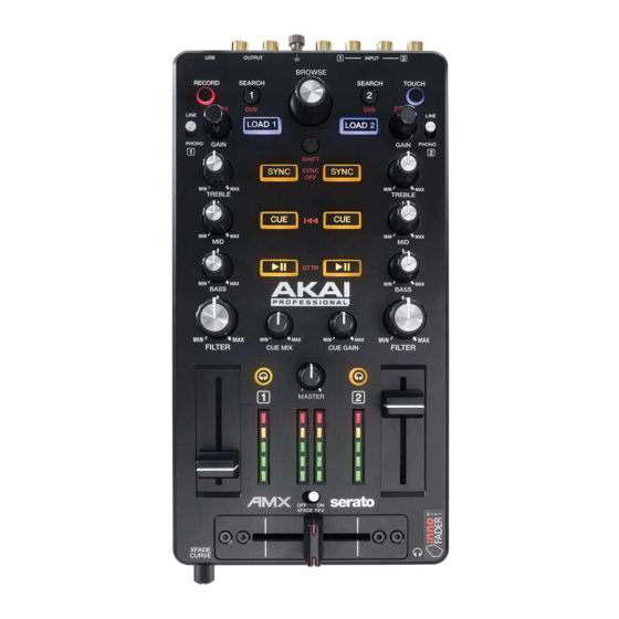
SERVICE MANUAL
Connections
Knobs
Power
Dimensions
(width x depth x height; no cable)
Weight
SPECIFICATIONS
1 1 1 1 USB port
2 2 2 2 RCA stereo (pairs) line/phono inputs
1 1 1 1 RCA stereo (pair) master output
1 1 1 1 1/8" (3.5 mm) TRS headphone output
1 1 1 1 360° touch-capacitive encoder
8 8 8 8 270° touch-capacitive knobs
2 2 2 2 360° encoders
3 3 3 3 270° knobs
USB-bus-powered
5.2" x 10.8" x 1.9"
13.3 cm x 27.4 cm x 4.8 cm
1.76 lbs.
0.8 kg
MODEL:AMX
Advertisement

Subscribe to Our Youtube Channel
Related Manuals for Akai AMX Serato


Summary of Contents for Akai AMX Serato
- Page 1 SERVICE MANUAL MODEL:AMX SPECIFICATIONS 1 1 1 1 USB port 2 2 2 2 RCA stereo (pairs) line/phono inputs Connections 1 1 1 1 RCA stereo (pair) master output 1 1 1 1 1/8" (3.5 mm) TRS headphone output 1 1 1 1 360° touch-capacitive encoder 8 8 8 8 270°...
-
Page 2: Disassembly Procedures
T e c h n i c a l S p e c i f i c a t i o n T e c h n i c a l S p e c i f i c a t i o n T e c h n i c a l S p e c i f i c a t i o n T e c h n i c a l S p e c i f i c a t i o n DISASSEMBLY PROCEDURES... - Page 3 2. DISASSEMBLE THE MAIN PCB ASSY’. (Fig.3)(Fig.4) (A) REMOVE THE GROUND LUG FROM THE TOP PANEL. (B) REMOVE THE NAME PLATE FROM TOP PANEL. (C) REMOVE 17 KNOBS FROM THE TOP PANEL. (D) REMOVE 13 NUTS AND 13 WASHERS (E) REMOVE 7 SCREWS FROM THE MAIN PCB ASSY’. (Fig.3) (Fig.4)
-
Page 4: Wiring Diagram
WIRING DIAGRAM (US) -
Page 5: Packing Diagram
PACKING DIAGRAM (US) -
Page 6: Explode Diagram
EXPLODE DIAGRAM (US/AUS) - Page 7 AK40AKA01 DESCRIPTION LEVEL AK40AKA01 AK40 USB USA AL4-71-0016 USB Cable 1.8m/CORD/2.0 BART-K00701 Rotate Knob BASJ5012B PU Stand LAC22AKA333 Bar Code Label LAC53AKA364 Safety Sticker LAC62AKA331 Bar Code Label(GTIN14) 0.25 LAC62AKA332 Bar Code Label(CODE39) 0.25 LAC67AKA362 Mini Fader Sticker LAC67MAR681 Label(Circle Limpid) LAC67YAH261 Label φ8mm Green MT1101878...
- Page 8 PT1130379 Bottom Housing PT15106179 VR Knob(032C) PT151063801 FADER INDICATE PAINTING WHITE PT1510638 FADER PU010010004 Conbuctive Foam SC0305FA2IBI Screw M3X5 HFB SC0308PBNI Screw SC0310RBBI Screw M3X10 PPB Tapping TWPC14A00201 MAIN PCB Assembly AA822524X IC SN74HC165PW U12,40 AA822757X Transistor 2SC3326 NPN SC-59 Q29,30,40,41 AL0-09-0044 Variable Resistor...
- Page 9 EC10735TLE Capacitor Electrolytic low ESR 100uF/35V C97,102 6.3*11mm EC10816 Capacitor Electrolytic 1000uF/16V 10*16mm C92,93 ECS10710D Capacitor Electrolytic 100UF 10V SMD-D C76,146 ECS15725FLE ECAP 150UF/25V 8*10MM SMD Low ESR ECS33716FLE ECAP 330uF/16V 8*10.2mm SMD LOW ESR ECS47635DLE ECAP 47UF/35V 6.3X5.7mm SMD-D Low ESR C116,117,119,120 IC74AHC02D IC 74AHC02D SOP-14...
- Page 10 RS022110F03 RES 221 1% SMD 0603 R88,434 RS022K10F03 RES 22K 1% SMD 0603 R22,37 RS030110F03 RES 301 1% 1/10W 0603 R250 RS047010F03 RES 470 1% SMD 0603 R265,584,585 RS047K10F03 RES 47K 1% SMD 0603 R568,572,576,580 RS04K710F03 RES 4.7K 1% SMD 0603 R569,573,577,581 RS084510F03 RES 845 1% SMD 0603...
- Page 11 TWPT11106502 Knob(STDV)Assembly PT11106502 Knob(STDV) PT11106503 Decoretive(STDV) PT113002401 Knob Deck(STDV)(Anodizeing) TWPT1110650401 Knob(MED) Assembly PT11106504 Knob(MED) PT1502909 Knob Deck(MED) TWPT15106169 Knob(LRG) Assembly PT113004001 Knob Deck(LRG)(Anodizeing) PT15106169 Knob WS073307IC Washer Flat WS1306505 Washer FLAT 13*6.5*0.5MM WS663309IC Spring Washer 3#...
- Page 12 3. Connect the headphone output into RCA inputs 3,4 4. Open the AK40 Test application with the MaxMSP Runtime 5. Set the MIDI Input and Output devices to AMX 6. Set the AUDIO Device Driver to “ad_asio Akai Professional AMX ASIO(64)” 7. Set Input to: Internal 8.
- Page 13 a. If test passed, the knob on screen corresponding to the physical potentiometer will turn green. 8. Move all Sliders to the minimum and maximum position. a. If test passed, the slider on screen corresponding to the physical slider will turn green. 9.
Need help?
Do you have a question about the AMX Serato and is the answer not in the manual?
Questions and answers