
Related Manuals for Teledyne 3010


Summary of Contents for Teledyne 3010
-
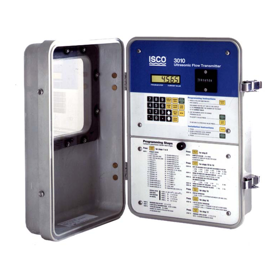
Page 1: Flow Transmitter
3010 Flow Transmitter Installation and Operation Guide Part #60-3403-171 of Assembly #60-3404-070 Copyright © 2001. All rights reserved, Teledyne Isco Revision V, February 2012. - Page 3 3010 Flow Transmitter Safety 3010 Flow Transmitter Safety General Warnings Before installing, operating, or maintaining this equipment, it is imperative that all hazards and preventive measures are fully understood. While specific hazards may vary according to location and application, take heed in the following general hygiene mishaps.
- Page 4 3010 Flow Transmitter Safety The equipment and this manual use symbols used to warn of Hazard Symbols hazards. The symbols are explained below. Hazard Symbols Warnings and Cautions The exclamation point within the triangle is a warning sign alerting you of important instructions in the instrument’s technical reference manual.
-
Page 5: Table Of Contents
3010 Flow Transmitter Table of Contents Section 1 Introduction 1.1 Manual Organization ..........1-1 1.2 Description. - Page 6 3010 Flow Transmitter Table of Contents 3.7.1 Mounting the Ultrasonic Level Sensor ......3-8 3.7.2 Minimization of Level Measurement Errors .
- Page 7 4-1 High-Low Alarm Relay Box (Cover Removed) ......4-2 4-2 Interconnection of 3010 and Alarm Boxe(s) ......4-4 4-3 Remote Totalizer .
- Page 8 3010 Flow Transmitter Table of Contents viii...
-
Page 9: Manual Organization
1.1 Manual Organization The purpose of this manual is to provide the information nec- essary to program, operate, maintain, and service the 3010 Flow Transmitter. To accomplish this, the manual is organized into five sections and an appendix. This first section is a general introduction to the flow transmitter. -
Page 10: Interfacing Equipment
Note Throughout this manual, we describe various accessories available for the 3010. We have listed the part numbers for all these items on an Accessory List, that you will find at the back of Appendix A Replacement Parts List. You can obtain part numbers for other Teledyne Isco equipment by calling the fac- tory. -
Page 11: Setup Step
Figure 1-2 Ultrasonic Level Sensor 1.3.1 SETUP Step The 3010 has a special feature to help you correctly align the ultrasonic level sensor. This Setup step lets you orient the ultra- sonic level sensor over the flow stream while an assistant watches the flow transmitter's display. -
Page 12: Controls, Indicators, And Terminal Blocks
1.4 Controls, Indicators, Table 1-1 lists the controls, indicators, and terminal blocks for wiring to the 3010 Flow Meter, and briefly describes their func- and Terminal Blocks tions. Refer to Figure 1-3 for a view of the terminal blocks. -
Page 13: Interior View Of Transmitter, Showing Terminal Blocks
3010 Flow Transmitter Section 1 Introduction Figure 1-3 Interior View of Transmitter, Showing Terminal Blocks... -
Page 14: Technical Specifications
The technical specifications for the 3010 and ultrasonic level sensor (USLS) are listed below in Tables 1-2 and 1-3. Specifications Table 1-2 Technical Specifications for the Model 3010 Flow Transmitter Size (H x W x D) inches x 10 inches x 7 inches (38.7 cm x 27 cm x 18.7 cm) -
Page 15: Section 2 Programming
Auxiliary equipment used with the 3010 connects to the terminal blocks on the printed circuit board in the bottom section of the flow transmitter case. 2.1.1 Ultrasonic Level... -
Page 16: Error Factors Affecting Performance
If, after approximately four minutes, the flow transmitter cannot obtain a valid reading, the 3010 will show EE 80 on the display. In such instances, it may be necessary to realign the level sensor or check the operation of the flow transmitter. -
Page 17: Error Factors And Flow Compensation
Noise – Background noise can interfere with the operation of the flow transmitter. The unit must filter out this noise, or it may trigger on the noise rather than the returned echo. The 3010 uses a tuned circuit to filter out unwanted noise outside the operating frequency. -
Page 18: Controls And Indicators
Wavelength – You can determine the wavelength of sound by dividing the velocity of the sound by the frequency. The frequency of the 3010 is about 49 kHz. You can find the length of a 49 kHz sound wave by dividing 1,125 feet /second by 49,000, which is 0.02296 feet or 0.276 inches. -
Page 19: Display
FUNCTION KEYS – The yellow keys let you enter the program of the 3010 at specific steps so you can change selections or numerical values. These keys govern specific programming steps, and will be described elsewhere. Refer to Section 2.3.3 for the detailed descriptions of the Function Keys. -
Page 20: Programming
Overview stored in memory, even if it is only the default program installed at the factory. To program the 3010, press the yellow FUNCTION KEYS. The display will show the step number on the left and the number of the choice currently selected (or the numerical value entered for steps requiring a value) on the right. -
Page 21: List Of Program Steps
3010 Flow Transmitter Section 2 Programming Note that you can do all programming for the 3010 in the shop, except for Setup (concerned with sensor alignment) and the Adjust Level step, which you must do at the job site after com- pleting the installation. -
Page 22: Programming Sequence In Detail
16. Display Operation (1. Flow rate 2. Level 3. Alternate between the two) Note Program step 17 only if the 3010 controls other external pro- cess equipment which operates from the standard 4–20 mA current loop. 17. 4–20 mA Output Operation (level, flow rate, with or with- out event mark.) -
Page 23: Primary Measuring Devices
With any choice but #34 in Step 2, the program advances auto- matically to Step 7. Step 7 - Maximum Head – The 3010 will request entry of a value for MAXIMUM HEAD. The display will show the value already in memory. You can enter possible values from 0.1 to 10 feet (0.31 to 3.04 meters). - Page 24 You would then enter 2, 6, 1 for this step. In this instance, you would place three “0” labels and the CF label to the right of the display. If the 3010 is connected to a Model 2312, you would then enter 1 (CF) in Step 13 and 3 in Step 14.
- Page 25 Step 15 - Reset Plotter Totalizer to Zero – This step allows you the option of resetting the totalizer on the remote plotter. It does not affect the mechanical totalizer on the 3010. An example of where you might use this is for studies of flow over specific periods of time.
- Page 26 This output, a variable DC current of 4-20 mA, changes with the level or flow rate measured by the 3010: 4 mA=0% flow or 0 level; 20 mA=100% flow rate, full-scale, or maximum head. The 4-20 mA current output is a standard industrial control format.
-
Page 27: Equations Used In Flow Conversion
2.3.4 Equations Used in The equations used for flow conversions in the 3010 are in Table Flow Conversion 2-2. Note that the equations provided for primary devices with data-only flow conversions (Palmer-Bowlus, “H”... -
Page 28: Default Program
3010 Flow Transmitter Section 2 Programming Table 2-2 Equations Used in the Model 3010 (Contin- Type and # of Device Flow Equation 14-22. Palmer-Bowlus Flume 14. 6” Q = KH 15. 8” Q = KH 16. 10” Q = KH 17. -
Page 29: Simplified 3010 Programming Flowchart
FLOW RATE AT MAXIMUM HEAD (0.001 to 9,999) Step 18 - Adjust Level Step 9 -Totalizer CURRENT LEVEL TOTALIZER To Remainder of Program (FT. –1.0 to 10.0)(M –0.31 to 3.05) SCALING (0 to 9,999) Figure 2-1 Simplified 3010 Programming Flowchart 2-15... -
Page 30: Programming Examples
Program Step, while the number on the right is the value currently held in memory. 2.4.1 Programming for a In this example, we will program the 3010 to select a 6-inch Parshall Flume Parshall flume with a maximum head of 1.5 feet. Flow rate will be displayed in GPM. - Page 31 3010 Flow Transmitter Section 2 Programming Press ENTER. Place the “GPM” label to the right of the display. 6. To enter the totalizer scaling, calculated above, press 1, 0, 5, 2. 1052 Press ENTER. The totalized flow in gallons would be the totalizer value x 100, so attach two “0”...
-
Page 32: Programming For A Cipolletti Weir
42,740 GPM, is larger than four digits. Divide by 10 so that flow rate at maximum head is less than 9,999. The value entered into the 3010 will then be only four digits long (42,740 10 = 4,274). Place a “0” label and the “GPM” label to the right of the display. - Page 33 3010 Flow Transmitter Section 2 Programming 3. Select the correct primary device from the list shown on the front panel. To select a Cipolletti weir, press 4. Press ENTER. 4. Enter the maximum head in feet that you expect to see at the primary measuring device.
- Page 34 11. Totalized flow in Step 9 was hundreds of cubic feet. Since hundreds would have two zeros to the right of the totalizer, press 2. Press ENTER. 12. To reset the totalizer on the remote plotter (Teledyne Isco Model 2312) to 0, press 1. Press ENTER. XXXX...
- Page 35 3010 Flow Transmitter Section 2 Programming 13. Press DISPLAY. To alternate between level and flow rate, press 3. Press ENTER. XXXX (Flow Rate) H XXXX (H = Height, or level) 14. Press 4-20 MA OUTPUT to select the information trans- mitted.
-
Page 36: Programming With The Equation (Device #34)
You use the equation to calculate flow in applications where you Equation (Device #34) cannot use the standard devices provided with the 3010. You can also use the special equation for rectangular weirs with end contractions if you need a more accurate level-to-flow rate con- version than the one programmed into the 3010. - Page 37 GPH by 1,000 (160,056 GPH 1,000 gallons per count = 160 counts per hour). The result, 160, is the value you enter into the 3010. Place 3 “0” labels and the “GAL” label to the right of the totalizer. 2-23...
- Page 38 3010 Flow Transmitter Section 2 Programming 1. Press PRIMARY DEVICE. 2. Select units of measure for level. To select feet, press 1. Press ENTER. 3. Select entry of an equation (#34) from the list of primary devices shown on the front panel; press 3, 4.
- Page 39 3010 Flow Transmitter Section 2 Programming Press ENTER. 9. To program the totalizer, enter the constant calculated above by pressing 1, 6, 0. Press ENTER. The totalizer will now totalize in thousands of gallons. Place 3 “0” labels and the “GAL” label to the right of the totalizer.
-
Page 40: Rectangular Weirs With End Contractions
P1, P2 = exponents To change the level-to-flow rate conversion for a rectangular weir with end contractions into an equation that you can program into the 3010, you must calculate the constants N1 and N2: N1 = 3.33(L)(H N = 3.33(–0.2)(H... -
Page 41: Programming Example For A Rectangular Weir With End Contractions
3010 Flow Transmitter Section 2 Programming Therefore, you would program the following equation into the flow transmitter for a 4-foot rectangular weir with end contrac- tions and a maximum head of 1 foot: Q 37.67(H ) – 3.767(H ) CFS... - Page 42 3010 Flow Transmitter Section 2 Programming Because these values are in CFS, we must convert from CFS to GPM by multiplying by 448.8. N1 = 56.51 x 448.8 = 25,362 N2 = –3.767 x 448.8 = –1,691 Because N1 and N2 must be in the range of –4,999 to 4,999, we must divide both these numbers by 10.
- Page 43 3010 Flow Transmitter Section 2 Programming 4. To enter the value for N1, press 2, 5, 3, 6. 2536 Press ENTER. 5. To enter the value for P1, press 1, (decimal), 5. Press ENTER. 6. To enter the value for N2, press +/-, 1, 6, 9.
- Page 44 3010 Flow Transmitter Section 2 Programming 10. Press DISPLAY MODE and press 1 to display flow rate. Press ENTER. XXXX (Flow Rate) 11. Press ADJUST LEVEL to set the current level in feet. Press (decimal), 7, 5. (the H will flash.) Press ENTER.
-
Page 45: Section 3 Installation
This is not only harmful to the 3010, but there is also the possibility of electric shock from the presence of AC power inside the unit. Always try to locate outside installations in relatively secure areas to min- imize the possibility of tampering or vandalism. -
Page 46: Portable Operation
3010 Flow Transmitter Section 3 Installation Because it uses an ultrasonic level sensor, the 3010 does not have to be mounted directly above the primary device, or even close to the flow stream. You can install the flow transmitter at a conve- nient, protected location and run the cable to the level sensor. -
Page 47: Connection To A Power Source
A 15-amp breaker is sufficient. Do not attach the flow transmitter to a circuit that already has other equipment on it. Do not connect the 3010 to a circuit controlled by an unrestricted ordinary wall switch. 3.2.3 Voltage Selector Switch A slide switch above TS1 selects 120- or 240-volt operation. -
Page 48: Wiring The Ultrasonic Level Sensor
It serves as a splice box between the level sensor and an extension cable. The extension cable then runs to the 3010. Extension cables of 25, 50, 100, and 250 feet (7.6, 15.2, 30.4, and 76.3 meters) are available from Teledyne Isco. -
Page 49: Connection To An Isco Sampler
The flow transmitter works with any of the Teledyne Isco sam- plers. If you use the 3010 with an Isco sampler in a flow-paced sampling system, you must connect them together. You can... -
Page 50: Connection To A Non-Isco Sampler
Section 3 Installation Locations Greater Than 22 Feet – For distances between the flow meter and sampler greater than 22 feet, Teledyne Isco has a kit consisting of a 6-pin M/S connector that attaches to a cus- tomer-supplied cable. Follow the instructions supplied with the kit to attach the connector to your cable. -
Page 51: Safety Considerations
3010 Flow Transmitter Section 3 Installation 3.6 Safety Considerations While you will generally install the 3010 Flow Transmitter above ground in relatively safe environments, you may have to locate the level sensor in a sewer or manhole. Before attempting instal- lation of the level sensor in such a hazardous location, please review the following safety information carefully. -
Page 52: Mounting The Ultrasonic Level Sensor
” male pipe thread with a conduit locknut to connect it to a mounting bracket or cable stiffener. Teledyne Isco also offers an optional mounting bracket to mount the level sensor. Figure 3-6 shows this bracket. -
Page 53: Minimization Of Level Measurement Errors
3.7.2 Minimization of Level In order to minimize measurement errors with the 3010, observe Measurement Errors the following precautions installing the ultrasonic level sensor. These are listed in the approximate order of their significance. - Page 54 3010 Flow Transmitter Section 3 Installation significantly higher than the surrounding air. Teledyne Isco has an optional sunshade available for its ultrasonic level sensors. Level Errors Due to Temperature Differences – E r r o r s caused by the ultrasonic level sensor operating at a different temperature than the ambient can be quite serious.
- Page 55 3010 Flow Transmitter Section 3 Installation Water Condensation – The ultrasonic level sensor will not operate properly if the bottom surface collects water droplets. This may occur if water condenses on the transducer surface as a result of high ambient humidity. Some people have found that mounting the ultrasonic level sensor horizontally and aiming it at a 45°...
-
Page 56: Foam And Oil On The Surface Of The Stream
3010 Flow Transmitter Section 3 Installation FOAM Figure 3-3 Foam and Oil on the Surface of the Stream Figure 3-4 Small Pipes and Narrow Channels 3-12... - Page 57 3010 Flow Transmitter Section 3 Installation Determining Suitability – The channel to be measured can be “pre qualified” by a simple equation which will determine whether the channel is wide enough to allow correct positioning of the ultrasonic sensor. Since the beam angle is 12°, the equation is: Minimum Width = .21 x Distance...
-
Page 58: Ultrasonic Level Sensor "Dead Band
DEAD BAND: The nonuseable distance (2 feet) between the USLS and the liquid surface. This requires that at maximum level the liquid surface must be at least 2 feet from the level sensor. DISTANCE “D” is the distance from the USLS to the liquid surface. For the Model 3010, this can be from 2 to 12 feet. -
Page 59: Usls Mounting Methods
3010 Flow Transmitter Section 3 Installation USLS Mounting Bracket Figure 3-6 USLS Mounting Methods 3-15... -
Page 60: Usls Mounting Methods (Continued)
3010 Flow Transmitter Section 3 Installation Figure 3-7 USLS Mounting Methods (continued) 3-16... -
Page 61: Section 4 Options And Accessories
4.1 High-Low Alarm Relay Teledyne Isco offers an alarm box that monitors flow rate infor- mation provided by the 3010 (see Figure 4-1). Relays trip when flow rate falls below or exceeds preset limits. High and low set points are user-selected and range from 0% to 99% in 1% incre- ments. -
Page 62: Setting The Limit Switches
The High-Low Alarm Relay Box contains a microprocessor that Switches compares serial data from the 3010 to set values for high and low alarm trip-points for the relays. Rotary switches inside the alarm box set the trip points. There are two rotary switches for each limit. -
Page 63: Wiring
Any color of wire or cable is acceptable, but make sure the connections end up the same as those shown. The maximum recommended distance between the 3010 and the alarm box is 250 feet (76 meters). The recommended wire gauge for interconnection cable is #18 AWG. -
Page 64: Connection To External Serial Devices
Devices a simplex serial output port providing ASCII level and flow rate data for remote transmission. Every 30 seconds, the 3010 transmits a line of data which includes level, units of level mea- surement, percentage of maximum flow rate, maximum flow rate, a total-flow value, units of flow, sample number, and bottle number. -
Page 65: Remote Totalizer
‘CR’ (carriage return) and an ‘LF’ (line feed). The large gaps between some of the words indicate extra character spaces which are defined for a 2312 plotter, but not for the 3010. 4.3 Remote Totalizer Teledyne Isco offers a remote totalizer for use with the 3010. It... -
Page 66: Extension Cables For The Sensor
3010 Flow Transmitter Section 4 Options and Accessories 4.4 Extension Cables for The ultrasonic level sensor used with 3010 has a 50-foot (15.2 m) cable attached. Strip this cable and expose the wires. Connect the Sensor these wires to the ULTRASONIC SENSOR and TEMP SENSOR terminals as described in Section 3.2.4. - Page 67 3010 Flow Transmitter Section 4 Options and Accessories Connect the cable to the 20 MA OUTPUT terminals of the 3010. Note which color conductor is on which terminal. For example, if the wires are black and white, connect the black wire to the + ter- minal of the 20 MA OUTPUT and the white wire to the –...
- Page 68 3010 Flow Transmitter Section 4 Options and Accessories...
-
Page 69: Section 5 Maintenance And Troubleshooting
Teledyne Isco recommends you become completely familiar with the routine maintenance presented here. While the 3010 is built to withstand severe field conditions, it will function best and remain most reliable if you perform these simple maintenance procedures. -
Page 70: Care Of The Sensor And Cables
3010 Flow Transmitter Section 5 Maintenance and Troubleshooting 5.2 Care of the Sensor and The ultrasonic level sensor (USLS) requires little periodic main- tenance. It is completely encapsulated to protect it from the envi- Cables ronment. The level sensor's transmitting surface is rubber. Do not scratch or score the surface;... -
Page 71: Fuse Replacement
5.5 Display Warnings The 3010 LCD displays various error messages to warn the user of problems in the program, or difficulties inside the flow trans- mitter. Messages will generally assume the format of:... -
Page 72: If Serious Problems Occur
3010 Flow Transmitter Section 5 Maintenance and Troubleshooting CAUTION Do not attempt to service the 3010 unless you are skilled in the analysis and repair of digital circuits. You must also know how to work safely with AC-powered equipment. If the technical information presented in the following sections is not clear to you, please do not attempt to go any further than changing the fuse, or cleaning the ultrasonic level sensor. -
Page 73: Precautions For Servicing Ac-Powered Equipment
• Make sure the crystal oscillator is running and at the proper frequency. 5.6.4 Precautions for The 3010 is a low-voltage, DC-powered device, and hazardous Servicing AC-Powered voltages are not present on the CPU board. However, the unit Equipment converts power from 120 or 240 VAC to the DC used to run the flow transmitter. -
Page 74: Precautions For Servicing Cmos Circuitry
5.6.5 Precautions for Most of the circuitry in the 3010 is made up of CMOS compo- Servicing CMOS nents. Because of the oxide gate structure of these devices, they... - Page 75 3010 Flow Transmitter Section 5 Maintenance and Troubleshooting • Avoid using a work surface made of an extremely good insulator. Avoid plastic counter tops or glass as they are good insulators. A metal surface is best, but do not let compo- nents connected to the AC line touch a metal surface, particularly a grounded one.
-
Page 76: Call For Assistance
Because of the difficulty and specialized equipment necessary to check program “software,” its detailed description is beyond the scope of this manual. The 3010 contains three printed circuit boards. The keypad is mounted under an aluminum plate just behind the top front panel. It connects to the ultrasonic board with a cable and connector. -
Page 77: Ultrasonic Board Description
3010 Flow Transmitter Section 5 Maintenance and Troubleshooting U6 is the microprocessor that controls the flow transmitter. U5 is an EPROM used to store the program for the microprocessor. U3 is a RAM where all temporary information and machine status are stored. - Page 78 3010 Flow Transmitter Section 5 Maintenance and Troubleshooting U16 is a D/A converter that provides a voltage to half of U15. U15 converts this voltage to a current that is proportional to the digital number stored in U16 by the microprocessor. This current is used for gain control in one of the circuits in U14.
- Page 79 3010 Flow Transmitter Section 5 Maintenance and Troubleshooting Figure 5-1 Terminal Printed Circuit Board Component Layout 5-11...
- Page 80 3010 Flow Transmitter Section 5 Maintenance and Troubleshooting Figure 5-2 CPU PCB Component Layout 5-12...
- Page 81 3010 Flow Transmitter Section 5 Maintenance and Troubleshooting Figure 5-3 Ultrasonic PCB Component Layout 5-13...
- Page 82 3010 Flow Transmitter Section 5 Maintenance and Troubleshooting 5-14...
-
Page 83: Appendix A Replacement Parts List
Replacement parts are called out in the following pages, followed by a list of accessories. Refer to the call-out in the adjacent table List to determine the part number for the item. Replacement parts can be purchased by contacting Teledyne Isco. Teledyne Isco Customer Service Department P.O. Box 82531... - Page 84 3010 Flow Transmitter Appendix A Replacement Parts List...
- Page 85 3010 Flow Transmitter Appendix A Replacement Parts List...
- Page 86 3010 Flow Transmitter Appendix A Replacement Parts List...
- Page 87 3010 Flow Transmitter Appendix A Replacement Parts List...
-
Page 88: Accessories List
Ultrasonic Calibration Target....................60-3004-143 Ultrasonic Sensor Sunshade (Includes Adaptor)..............60-3004-142 Sampler Connector Kit (3000 Series Flow Transmitter to Teledyne Isco Sampler) ....68-3010-013 (Use with user-supplied 2-wire cable only, 1,000 feet maximum.) Connect Cable, 3000 Series Flow Transmitter to Teledyne Isco Sampler (22 feet)....60-1394-077 Flow Meter to Sampler “Y”... -
Page 89: Appendix B General Safety Procedures
The second section deals with the special problem of hazardous gases found in sewers. WARNING The 3010 has not been approved for use in hazardous locations as defined by the National Electrical Code. CAUTION Before any sampler is installed, the proper safety precautions must be taken. -
Page 90: Planning
3010 Flow Transmitter Appendix B General Safety Procedures Sharp Edges – Sharp edges of items in or near a manhole may cause cuts or bruises. Lifting Injuries – Unless proper tools are used to remove manhole covers, back injuries or injuries to hands or feet may result. -
Page 91: Traffic Protection
3010 Flow Transmitter Appendix B General Safety Procedures overcome or injured. One man cannot lift an unconscious man out of a manhole. The persons stationed at the surface should also function as guards to keep people and vehicles away from the manhole opening. -
Page 92: B.1.9 Emergencies
3010 Flow Transmitter Appendix B General Safety Procedures B.1.9 Emergencies Every member of the crew should be instructed on procedures to be followed in cases of an emergency. It is the duty of each crew chief to have a list of emergency phone numbers, including the nearest hospital and ambulance service, police precinct, fire station, and rescue or general emergency number. - Page 93 3010 Flow Transmitter Appendix B General Safety Procedures The lowest oxygen concentrations that I have observed in a sewer atmosphere was 13 percent. It was in a sealed chamber, near sea level, upstream from an inverted siphon on a metropolitan trunk.
-
Page 94: Hazardous Gases
3010 Flow Transmitter Appendix B General Safety Procedures amounts that could cause discomfort and illness, but under that condition, the explosion hazard would be far more serious. The explosimeter tests, as well as the sense of smell, would warn of the danger. - Page 95 3010 Flow Transmitter Appendix B General Safety Procedures Table B-1 Hazardous Gases (Continued) Specific Explosive Likely Max. Safe Simplest and Gravity Safe 60 Range (% by Location Most Chemical Common Physiological 8 Hour Cheapest or Vapor Min. vol. in air)
- Page 96 3010 Flow Transmitter Appendix B General Safety Procedures Table B-1 Hazardous Gases (Continued) Specific Explosive Likely Max. Safe Simplest and Gravity Safe 60 Range (% by Location Most Chemical Common Physiological 8 Hour Cheapest or Vapor Min. vol. in air)
- Page 97 3010 Flow Transmitter Appendix B General Safety Procedures Table B-1 Hazardous Gases (Continued) Specific Explosive Likely Max. Safe Simplest and Gravity Safe 60 Range (% by Location Most Chemical Common Physiological 8 Hour Cheapest or Vapor Min. vol. in air)
- Page 98 3010 Flow Transmitter Appendix B General Safety Procedures B-10...
- Page 99 REV. 2-94 This worksheet will help you to program the Model 3010. Circle your selections with a pencil. Where numeric values are required, write them in. Then program the Flow Transmitter by entering the values you selected on the worksheet.
- Page 101 Lincoln, NE 68504, U.S.A. customer’s facility and the repair facility. * This warranty applies to the USA and countries where Teledyne Isco Inc. does not have an authorized dealer. Customers in countries outside the USA, where Teledyne Isco has an authorized dealer, should contact their Teledyne Isco dealer for warranty service.
Need help?
Do you have a question about the 3010 and is the answer not in the manual?
Questions and answers