Table of Contents
Advertisement
Quick Links
OPERATING INSTRUCTIONS FOR
2000 XTC
Thermal Conductivity Transmitter
P/N M74838
ECO: 04-0203
REV 1
DANGER
Toxic gases and/or flammable liquids may be present in this monitoring system.
Personal protective equipment may be required when servicing this instrument.
Hazardous voltages exist on certain components internally which may persist
for a time even after the power is turned off and disconnected.
Only authorized personnel should conduct maintenance and/or servicing.
Teledyne Analytical Instruments
Advertisement
Table of Contents

Related Manuals for Teledyne 2000 XTC


Summary of Contents for Teledyne 2000 XTC
- Page 1 OPERATING INSTRUCTIONS FOR 2000 XTC Thermal Conductivity Transmitter P/N M74838 ECO: 04-0203 REV 1 DANGER Toxic gases and/or flammable liquids may be present in this monitoring system. Personal protective equipment may be required when servicing this instrument. Hazardous voltages exist on certain components internally which may persist for a time even after the power is turned off and disconnected.
- Page 2 Any safeguards required such as locks, labels, or redundancy, must be provided by the user or specifically requested of Teledyne at the time the order is placed. Therefore, the purchaser must be aware of the hazardous process conditions. The purchaser is...
- Page 3 Consult the factory for additional information for gas analysis not specified at the time of purchase. Instrument Serial Number: _______________________ Instrument Range: _______________ Calibrated for: _______________ Background Gas: _______________ Zero Gas: _______________ Span Gas: _______________ Teledyne Analytical Instruments...
-
Page 4: Safety Messages
2000 XTC Safety Messages Your safety and the safety of others is very important. We have provided many important safety messages in this manual. Please read these messages carefully. A safety message alerts you to potential hazards that could hurt you or others. - Page 5 Manuals do get lost. Additional manuals can be obtained from Teledyne at the address given in the Appendix. Some of our manuals are available in electronic form via the internet. Please visit our website at: www.teledyne-ai.com.
-
Page 6: Table Of Contents
2000 XTC Table of Contents List of Figures viii List of Tables Introduction………………………………………………………………1 1.1 Overview 1.2 Typical Applications 1.3 Main Features of the Transmitter 1.4 Operator Interface Operational Theory……………………………………………………...5 2.1 Introduction 2.2 The Thermal Conductivity Sensor 2.3 Sample System 2.4 Electronics and Signal Processing 2.4.1 Transmitter... - Page 7 Thermal Conductivity Transmitter Maintenance…………………………………………………………….22 4.1 Routine Maintenance 4.2 Troubleshooting 4.3 Fuse Replacement Appendix………………………………………………………………...26 Specifications Recommended Spare Parts List Reference Drawings Index……………………………………………………………………...29 Teledyne Analytical Instruments...
-
Page 8: List Of Figures
Figure 2-2: Recommended External Sample System…………………8 Figure 2-3: Internal Piping………………………………………………..8 Figure 2-4: Block Diagram of 2000 XTC………………………………..9 Figure 2-5: Model 2000 XTC External Wiring Diagram……………..11 Figure 3-1: Mounting Dimensions for Sensor Unit…………………...13 Figure 3-2: Mounting Dimensions for Interface Unit…………………14 Figure 3-3: Power and Output Connections to Galvanic Isolator…..16 Figure 3-4: Cable Connection to Galvanic Isolator Module…………16... -
Page 9: List Of Tables
Thermal Conductivity Transmitter List of Tables Table 3-1: Heater Temperature…………………………………..19 Table 3-2: Concentration from Output Current………………….21 Table 4-1 Troubleshooting………………………………………...222 Table 4-2: Fuses……………………………………………………244 Teledyne Analytical Instruments... - Page 10 Since the use of this instrument is beyond the control of Teledyne, no responsibility by Teledyne, its affiliates, and agents for damage or injury from misuse or neglect of this equipment is implied or assumed.
-
Page 11: Introduction
Transmitter is an instrument designed to analyze the gas concentration of a binary gas mixture. This manual covers the CENELEC/ATEX approved model 2000 XTC Thermal Conductivity Transmitter. These units are rated as intrinsically safe and may be used in Class I, Group A, B, C, D, Div. 1 (North America) and EEx ib IIC T3 (IEC/Europe) hazardous environments. -
Page 12: Main Features Of The Transmitter
1.4 Operator Interface The user does not interact with the transmitter directly. The standard 2000 XTC Thermal Conductivity Transmitter provides a 4-20 mA output signal proportional to the concentration of the gas being analyzed. This signal can be used to drive devices such as displays, concentration alarms, user-supplied devices, or it can be monitored using a chart recorder. -
Page 13: Figure 1-1: Xtc Transmitter Modules
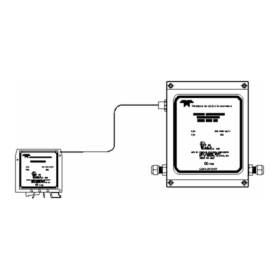
Thermal Conductivity Transmitter Introduction Figure 1-1 shows the 2000 XTC Thermal Conductivity Transmitter. The instrument is comprised of two modules: the transmitter unit and the galvanic isolator unit. The transmitter is located at the sample point (which can be a hazardous area) and is where the sample gas input is converted into an electrical output signal. - Page 14 Operational Theory 2000 XTC Teledyne Analytical Instruments...
-
Page 15: Operational Theory
Thermal Conductivity Transmitter Operational Theory Operational Theory 2.1 Introduction The 2000 XTC is comprised of two subsystems: 1. The thermal conductivity sensor and transmitter 2. Galvanic isolator and power supply The system directs a sample gas into the transmitter. Internally, the sample is passed to the sensor and heated without contaminating or altering the sample in any way. -
Page 16: Figure 2-1: Thermal Conductivity Sensor
Figure 2-1 shows a cross section of the sensor used in the 2000 XTC. A resistor is mounted on a heated membrane to which the sample gas is exposed. -
Page 17: Sample System
Figure 2-2 is a typical sample system for delivering sample and calibration gases to the transmitter. It uses two (2) 3-way valves to deliver either sample or calibration (zero or span) gas to the transmitter. Teledyne Analytical Instruments... -
Page 18: Figure 2-2: Recommended External Sample System
Operational Theory 2000 XTC Figure 2-2: Recommended External Sample System The sample path within the transmitter is a straight-through path. Gas encounters no dead space. This minimizes residual gas pockets that can interfere with accurate analysis. Stainless steel 1/4” tube fittings are installed (6mm are available) for connecting the external sample system to the transmitter. -
Page 19: Electronics And Signal Processing
Figure 2-4 is a block diagram of the instrument electronics. Figure 2-4: Block Diagram of 2000 XTC 2.4.1 Transmitter The differences in thermal conductivities of the sample gas provide... -
Page 20: Galvanic Isolator
Operational Theory 2000 XTC membrane. The amount of voltage needed to offset the analog output (i.e. to null the circuit when the resistance changes due to temperature effects) is measured and applied. A preprogrammed microcontroller with EPROM uses the offset voltage from the analog stages to generate a linearized output voltage signal, which is then converted to a 0-4 mA current. -
Page 21: Connection Cable
Figure 2-5 shows the pin configuration for this cable. The interface unit and the transmitter module can be separated up to 30.5 meters (100 feet). Figure 2-5: Model 2000 XTC External Wiring Diagram Teledyne Analytical Instruments... -
Page 22: Installation
Installation For Intrinsically Safe (IS) installation, special considerations are required. The 2000 XTC Thermal Conductivity Transmitter has been designed to be Intrinsically Safe using an integral galvanic isolator module that limits power to and from the transmitter in a hazardous location. When... -
Page 23: Mounting The Transmitter
Thermal Conductivity Transmitter Installation 3.2 Mounting the Transmitter The Model 2000 XTC Transmitter is intended for indoor use only. The transmitter module is designed for operation in a hazardous location. It should be mounted in an area close to the sample take- off point. -
Page 24: Gas Connections
Installation 2000 XTC Figure 3-2: Mounting Dimensions for Interface Unit Once the transmitter and galvanic isolator are securely mounted, connect the interface cable to the transmitter. If the cable is not attached to the safety barrier, connect the wires to the unit as described in Section 3-5. -
Page 25: Electrical Connections
Connect the positive lead from the 24 VDC source to terminal 7 and the negative lead to terminal 8 on the galvanic isolator module as shown in Figure 3-3. Teledyne Analytical Instruments... -
Page 26: Figure 3-3: Power And Output Connections To Galvanic Isolator
Installation 2000 XTC 4-20 mA Output Signal The output signal from the instrument is available to the user as a 4-20 mA current. It has a maximum impedance of 700 Ohms. Typically, this output is used to display concentration using a digital meter or chart recorder or to trigger an alarm circuit. -
Page 27: Calibration
The following calibration procedures assume that suitable calibration gas connections have been made and that a read-out device capable of interpreting a 4-20 mA current is attached to the output terminals of the galvanic isolator module (see Section 3-5). Teledyne Analytical Instruments... -
Page 28: Adjusting Internal Temperature
Installation 2000 XTC Figure 3-5: Temperature and Calibration Adjustment Location 3.6.1 Adjusting Cell Block Temperature Note: A separate heater inside the transmitter case controls the transmitter cell block temperature. It has been adjusted at the factory for optimum performance based on your application. -
Page 29: Zero Calibration
If a different gas is used, the resulting output signal may not be linear with concentration. You also may experience difficulty in Teledyne Analytical Instruments... -
Page 30: Span Calibration
Installation 2000 XTC zeroing this instrument when using a gas different than the gas specified at the time of purchase. To zero calibrate this instrument: 1. Connect a read-out device to the 4-20 mA output signal terminals on the galvanic isolator module according to Section 3-5. - Page 31 5. If the zero calibration must be changed after initial span calibration, recalibrate the span. Table 3-2: Concentration from Output Current Concentration Current 0-1% 0-10% 0-50% 90-100% 0-100% Output Full Full Full Full Full (mA) Scale Scale Scale Scale Scale 10.4 12.0 13.6 15.2 16.8 18.4 Teledyne Analytical Instruments...
-
Page 32: Maintenance
Both boards are easily accessible after removing the respective front covers. 4.2 Troubleshooting The following table offers guidelines for diagnosing and correcting common problems associated with the 2000 XTC Thermal Conductivity Transmitter. Table 4-1 Troubleshooting Symptom... - Page 33 See transmitter case Section 3.6.1. Loose cable connection A) Check interconnection cable. B) Check heater cable. See Figure 4.1. C) Check sensor cable. See Figure 4.1. Damaged sensor A) Replace sensor. Contact factory. Teledyne Analytical Instruments...
-
Page 34: Fuse Replacement
Maintenance 2000 XTC Figure 4-1: Cable Identification in Transmitter 4.3 Fuse Replacement There are four fuses installed in the galvanic isolator module for circuit protection. The main fuse (F1) is accessible after removing the fuse holder cover. All other fuses require separating the 2 galvanic isolator modules. -
Page 35: Figure 4-2 Fuse Location
• Gently pry out the blown fuse and replace with an exact replacement according to Table 4-2. • Reassemble the isolator modules and reinsert the assembly into its housing or mounting rail. Teledyne Analytical Instruments... -
Page 36: Appendix
Appendix 2000 XTC Appendix Specifications System: Dual module: transmitter and galvanic isolator Enclosure: Galvanic isolator: plastic DIN mountable case Transmitter: aluminum case, panel mountable, Nema 4X, IEC 60529 and IP 66 rated Classification: ATEX EEx ib IIC T3 (Europe) Power Requirements: 24VDC, 10.8 watt max power consumption (8 watts normal) Ranges: Specific application determined by user. - Page 37 Calibration Controls: Zero, span and temperature control Fuses: Input power circuit: 400 mA Output Signal Circuit: 50 mA Heater Circuit: (2) 160 mA Mounting (transmitter): Wall-mount (see section 3.2) Mounting (interface unit): DIN-rail mounting (see section 3.3) Teledyne Analytical Instruments...
-
Page 38: Recommended Spare Parts List
Appendix 2000 XTC Recommended Spare Parts List Qty. Part Number Description Bulkhead compression fitting, 1/4” tube C74627 Galvanic isolator board #1 C74632 Galvanic isolator board #2 C73750 T/C Transmitter Board A74933 T/C Sensor Assembly B74934 Cable assembly, interconnect F1668 Fuse, Fast-acting 5mm x 20mm, 400 mA... -
Page 39: Index
E to I converter 6, 9 open circuit voltage EEx ib IIC T3 operating range electrical connections operating temperature enclosure opto-coupler external sample system See sample output connections system output current factory calibration Teledyne Analytical Instruments... - Page 40 Index 2000 XTC output signal 2, 5, 6, 10 signal output 0-4 mA 9, 11, 16 signal processing 5, 9 4-20 mA 9, 16 span gas PC board 9, 17, 22 span potentiometer See potentiometer pin configuration spare parts potentiometer...
Need help?
Do you have a question about the 2000 XTC and is the answer not in the manual?
Questions and answers