Table of Contents
Advertisement
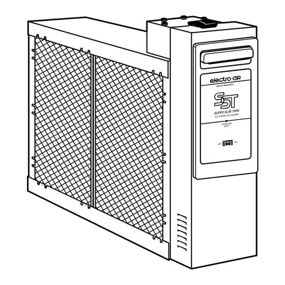
Electronic Air Cleaner
SST
Super Slim Twin
Model Number
10C26S-010
14C26S-010
16C28S-010
20C26S-010
Please read and familiarize yourself with the contents of this manual
before installing, operating or performing maintenance on the unit.
UL Listed
CSA Certified
OWNERS MANUAL
Installation
•
Operation
•
Basic SST Service Guide
•
Technical Repair Guide
•
Repair Parts
•
Printed In U.S.A.
by White-Rodgers
Part No. 37-6068B
Replaces 37-6068A
DG ERS
WH ITE -RO
0021
Advertisement
Table of Contents

Related Manuals for Electro-Air 10C26S-010


Summary of Contents for Electro-Air 10C26S-010
- Page 1 White-Rodgers Electronic Air Cleaner Super Slim Twin DG ERS WH ITE -RO Model Number 10C26S-010 14C26S-010 16C28S-010 20C26S-010 OWNERS MANUAL Installation • Operation • Basic SST Service Guide • Technical Repair Guide • Repair Parts • Please read and familiarize yourself with the contents of this manual before installing, operating or performing maintenance on the unit.
-
Page 2: Table Of Contents
Rules for Safe Installation and Operation ..2 How the Air Cleaner Works ......3 Model 10C26S-010 is designed for heating or cooling blowers delivering 600 to 1200 cubic feet of air per minute Construction of the Air Cleaner....... 3 (cfm.) -
Page 3: How The Air Cleaner Works
HOW THE AIR CLEANER WORKS Dirt particles flowing through the ducts (Figure 1) first enters the pre-filters (A) where large particles (hair, lint, Dirty Air In Clean Air Out etc.) are trapped. Smaller particles (smoke, dust, pollen, etc.) pass through these pre-filters and enter the ionizing section (B). -
Page 4: Preinstallation
If your furnace duct system has a pre-installed boot, MODEL NO. discard front cover of boot and slide the air cleaner 10C26S-010 24 3/4 21 5/16 18 5/8 13 9/16 16 7/16 19 1/16 component inside the boot. (Applies to 14C26S-010 and 14C26S-010 29 11/16 26 1/4 23 5/8 13 9/16 16 7/16 19 1/16 20C26S-010.) - Page 5 TYPICAL MOUNTING POSITIONS Air Flow Air Flow Air Flow Rear View Rear View Figure 6 Figure 8 Figure 7 BASEMENT FURNACE HIGHBOY FURNACE (LOWBOY) (Figure 6) (Figure 8) COUNTERFLOW FURNACE (Figure 7) Cleaner is mounted hori- Side installation. Cleaner zontally in return plenum, is mounted vertically, Cleaner is mounted horizon- just above furnace.
-
Page 6: Installation
INSTALLATION REMOVE OLD FILTER AND DISCARD (Figure 12) NOTE: This filter may be mounted in the furnace compart- ment. CLEAN BLOWER COMPARTMENT Figure 12 It is suggested that the furnace blower compartment, blower and blower housing be cleaned to ensure clean air circulation. -
Page 7: Wiring Instructions
10. With the cabinet Installed, reinstall pre-filter(s) and WIRING INSTRUCTIONS collecting cell(s) (Figure 19). NOTE: The contact button and handles on the cell 7. With the cabinet installed, the air cleaner can now be must be facing you and ionizing wires must be on the wired to electrical input source. -
Page 8: Operation
OPERATION 1. With the 120 VAC power turned on at the circuit breaker for the furnace, push the air cleaner ON-OFF switch to the “ON” position (Figure 20). 2. With the furnace blower running, the air cleaner will be operating. An arcing or “snapping” sound may be heard. -
Page 9: Specifications
Make sure wire is securely anchored at each end. Ionizing Wire Figure 21 SPECIFICATIONS SPECIFICATIONS 10C26S-010 14C26S-010 16C28S-010 20C26S-010 Rated Capacity 600 - 1200 cfm 1000 - 1600 cfm 1000 - 2000 cfm 1600 - 2200 cfm Max. -
Page 10: Basic Sst Service Guide
BASIC SST SERVICE GUIDE This guide will cover most homeowner complaints. If, after checking the items listed, the unit still fails to operate properly, contact the nearest Authorized Service Center. SERVICE INDICATION SERVICE CHECKS ON/OFF switch “ON” Unit functioning Normally Blower ON Operating Light ON ON/OFF switch “ON”... -
Page 11: Technical Repair Guide
TECHNICAL REPAIR GUIDE All voltage measurements indicated can be made with a WARNING high voltage D.C. probe and a general purpose volt ohm meter. For example: Simpson 260 or equivalent. Do not attempt repair of this unit unless you are familiar with the necessary tools, equipment, util- For test purposes, the air flow switch may be “wired out”... - Page 12 POWER SUPPLY 4. Using a standard extension cord, apply 120 VAC to power pack. Turn power switch to “ON” position. CHECKOUT PROCEDURE 5. Connect meter negative (-) lead to metal frame of 1. Turn power switch to the “OFF” position and remove collecting cell.
- Page 13 OZONE REDUCTION All electronic air cleaners typically produce a small amount of ozone that is within established limits. Some customers may notice an odor especially at high altitudes or low air flow rates. This power supply has a “hairpin” shaped jumper wire labeled W1 (see Fig 24) that can be cut and Cut and separate separated in case of such complaints.
-
Page 14: Repair Parts
REPAIR PARTS... - Page 15 2. The PART DESCRIPTION 3. The MODEL NUMBER 4. The NAME OF ITEM - Electronic Air Cleaner. Always order by “PART NUMBER” . . . Not by “ITEM NUMBER” PART NUMBER ITEM DESCRIPTION 10C26S-010 14C26S-010 16C28S-010 20C26S-010 Cabinet Pre-Filter • F825-0431 •...
- Page 16 NOTICE TO CONSUMERS White-Rodgers Electronic Air Cleaner Dear Consumer; White-Rodgers would like to thank you for purchasing a White-Rodgers Electronic Air Cleaner or product containing a White-Rodgers Electronic Air Cleaner. Although White- Rodgers does not extend a warranty directly to consumers, White-Rodgers does extend a warranty to Wholesalers and Original Equipment Manufacturers who use White-Rodgers Products.
Need help?
Do you have a question about the 10C26S-010 and is the answer not in the manual?
Questions and answers