
Related Manuals for Welch Allyn SureTemp 670


Summary of Contents for Welch Allyn SureTemp 670
- Page 1 Thermo Menu Operation Manual ® ® SureTemp & SureTemp 4 Model 670 & Model 675 Thermometer Technical Manual...
- Page 2 © 1996 by Welch Allyn, Inc. All rights reserved. No part of this manual may be reproduced or transmitted in any form or by any means, electronic or mechanical, including photocopy, without prior consent in writing from Welch Allyn. Printed in the U.S.A.
-
Page 3: Table Of Contents
Technical Manual TABLE OF CONTENTS WARRANTY ............................1 SPECIFICATIONS ..........................2 OPERATIONAL CHARACTERISTICS ....................2 INTRODUCTION ..........................2 BASIC SYSTEM DESCRIPTION .......................3 Operating Controls and Components....................4 Setup ..............................4 Instrument Reset/Self Tests ......................4 Probe Initialization/Self Tests ......................5 Normal Mode .............................6 Monitor Mode.............................7 Pulse Timer ............................7 Backlight/Temperature Recall......................7 F/C Switch ............................8 Biotech Mode.............................8... - Page 4 Welch Allyn, Inc. Temperature Measurement and Display ..................16 Battery Voltage Reading........................17 A/D Power Control ........................... 17 Probe Detection..........................17 Probe Warming (675 Oral probes only) ................... 18 EEPROM ............................19 Liquid Crystal Display ........................19 Backlight/Temperature Recall......................20 Horn..............................
-
Page 5: Warranty
Allyn, Inc. (Welch Allyn) is warranted to be free from original defects in material and workmanship under normal use and service for a period of one year from the date of first shipment from Welch Allyn. This warranty shall be fulfilled by Welch Allyn or its authorized representative repairing or replacing at Welch Allyn's discretion, any such defect, free of charge for parts and labor. -
Page 6: Specifications
Input: 28.9 o C to 42.2 o C (84.0 o F to 108.0 o F). Display range: ± 0.2 o F in the Monitor mode and in a water bath per Welch Allyn Laboratory Accuracy: document number 90565-000. Meets the proposed ASTM clinical test criteria. -
Page 7: Basic System Description
The Model 675 instrument has a key in the connector receptacle to disallow any but Model 675 probes. The probe covers are unchanged from previous models and are compatible across all of Welch Allyn and Diatek thermistor based thermometers. Welch Allyn’s thermistor based probes can be identified by color... -
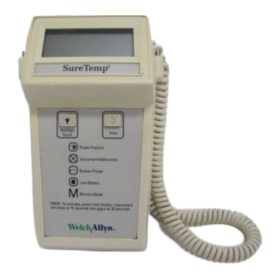
Page 8: Operating Controls And Components
Welch Allyn, Inc. •F •C NORMAL MONITOR Probe cover box Probe handle collar Probe Probe cover ejection button Display Probe cover storage well Backlight/Recall switch Fahrenheit/Celsius select switch Timer switch Normal/Monitor mode select switch Display legends Probe storage channel Battery access door... -
Page 9: Probe Initialization/Self Tests
With an instrument that passed the Instrument Reset/Self Tests section, install the probe connector first (with the Diatek or Welch Allyn logo showing) and then fully insert the probe shaft into the storage channel. Observe the display of the probe type. For Model 670, this probe type display will be very brief (less than 1 second.) For Model 675 Oral probes, the probe type will be displayed for about 10 to 15 seconds or possibly... -
Page 10: Normal Mode
Welch Allyn, Inc. If the display goes blank after the probe type display, the probe has passed its tests and the instrument is ready for use. Do not withdraw the probe during this self test. If the display shows an error code (such as E5.4), the probe is suspect. -
Page 11: Monitor Mode
Monitor mode is also useful in testing the accuracy of the combined probe/instrument system when the probe can be warmed to a known temperature, as with a Welch Allyn Model 9600 Calibration Tester or in a water bath. -
Page 12: F/C Switch
Welch Allyn, Inc. button turns on the backlight only for the duration of the button press and then at the end of a Normal mode temperature, the reading will display with the backlight for 5 seconds. Note: When a temperature is recalled, the mode in which it was obtained (Normal or Monitor) will be shown independent of the present setting of the mode switch. -
Page 13: Battery Life
“r X.X” where “X.X” is a number such as 1.8. This can be helpful when discussing operation with Welch Allyn customer support. 8. Press the Backlight/Recall button once to advance to the repeating display test. This is the same display test as initiated when batteries are first installed. -
Page 14: Preventative Maintenance
Welch Allyn, Inc. PREVENTATIVE MAINTENANCE The following preventative maintenance is recommended to maximize uninterrupted service on the Model 670 SureTemp and 675 SureTemp 4 Thermometer: Units which are in service on a regular basis should have the following preventative maintenance performed every 6 months: Visually inspect the thermometer for physical damage which might cause future product failure. -
Page 15: Battery Removal And Replacement
9. Install the probe connector and insert the probe into the storage channel which will start the probe initialization process. 10. Verify proper calibration of the thermometer and probe using the Welch Allyn Model 9600 Calibration Tester. Battery Removal and Replacement 1. -
Page 16: Calibration Testing
2 minutes to the final temperature. The reading on the thermometer must be within the range specified on the 9600. Refer to the Model 9600 Operation Manual for complete instructions. Note: All Welch Allyn and Diatek thermometers (thermistor and infrared ear thermometers can be checked in the Model 9600.) If you are having problems with the use of the Model 9600, refer to the Troubleshooting section in the Model 9600 Operation Manual. -
Page 17: Theory Of Operation
Technical Manual THEORY OF OPERATION Technical Overview The heart of the Model 670 and Model 675 is comprised of three custom integrated circuits which provide most of the microcontroller and analog circuit functions. All control and display functions are governed by the microcontroller (U2), all analog interfacing to the microcontroller, probe, horn and backlight is provided by U1, and operating parameter data is handled by the EEPROM U3. -
Page 18: Probe Enhancements
Welch Allyn, Inc. Probe Enhancements The Model 670 and Model 675 series thermometers have the capability to detect probe type - oral vs. rectal. This allows the oral temperatures to be as fast as possible (10 seconds in the 670 and 4 seconds in the 675) by using different operating modes based on probe type. -
Page 19: Normal Mode, Model 670
Technical Manual Normal Mode, Model 675 The Oral probe is pre-warmed using a pulse width modulation (PWM) controller to 33.9 C (93 F) upon extraction from the storage channel. When the probe is first extracted and colder than 33.9 C, the pulse widths are at a maximum percentage ON vs. -
Page 20: Reset/Self Tests
Welch Allyn, Inc. When the reset signal is complete, the microprocessor launches a series of self checks which include RAM test, ROM test, EEPROM test, instruction set test, self calibration tests (PTB test, hi cal, low cal), probe warmer circuitry tests, probe test, battery voltage test and ambient temperature test. Any failures here will cause a specific error code to be displayed to assist debugging. -
Page 21: Battery Voltage Reading
Technical Manual the discharge current but constitutes a very small constant DC resistance so it has no effect on results. Its only purpose is for RFI suppression. C3, C10, C11, C12 and C13 are also only for RFI, and ESD purposes. In Monitor mode a calibration cycle, where each of the fixed resistors is measured by the A/D function, is performed once every second. -
Page 22: Probe Warming (675 Oral Probes Only)
Welch Allyn, Inc. Probe connector installation does not “wake” the instrument up. When the probe shaft is stowed, the probe switch places voltage on U2 pin 23 via R24. This “wakes up” the processor which then reads the RAM flag and sees that the probe logic lines are indicating a probe is connected. -
Page 23: Eeprom
Technical Manual Once the probe has been brought near 33.9 C (93 F), the pulse widths are reduced to maintain this temperature. This is when the display switches from the all segments display test to “OrL” indicating that the unit is ready for placement in the mouth. Note: Do not confuse this with the displays during probe characterization, where “OrL”... -
Page 24: Backlight/Temperature Recall
Welch Allyn, Inc. The momentary backlight switch (S4) pulls processor pin 39 low. R19 acts as a pull up to return this line high when not in use. This line is also run to test connector J3 pin 6 to allow automated testing of this function during factory test. -
Page 25: Error Code Table
Technical Manual Non-recoverable errors are generated from internal test failures that are catastrophic (or from promoted recoverable errors). The error code and any appropriate icon will be displayed along with the “[X]” Instrument Malfunction icon. The only way to continue at this point is to reset the electronics by removing the batteries. NOTE: The error codes E2.1, E2.3, E3.0, E3.1, E3.2 and E4.1 can sometimes be caused by a faulty probe. -
Page 26: Troubleshooting
Welch Allyn, Inc. Error Code Table (continued) System Functional Errors E3.0 NON-RECOVER Low battery error E3.1 RECOVERABLE PTB test error E3.2 TRANSITORY Outside operating temp range Math Errors E4.0 RECOVERABLE Floating point over flow E4.1 RECOVERABLE Log of zero is undefined Warmer and Probe Errors E5.0... -
Page 27: Terminology
Technical Manual Power and ground are available at the end terminals of slide switches S2 or S3. Terminology Many standard abbreviations are used in this section (and elsewhere): printed circuit board (the board itself) PCB holding the display assembly printed circuit assembly (the board Digital Multi-Meter with all its components) main... -
Page 28: Troubleshooting Table
Welch Allyn, Inc. Troubleshooting Table SYMPTOM POSSIBLE CAUSE PROCEDURE No operation Dead batteries, no Refer to Battery Replacement section batteries, battery missing, on page 11. Check that all batteries battery incorrectly installed are installed in proper direction. Reset electronics (see Instrument... - Page 29 Technical Manual Troubleshooting Table (continued) SYMPTOM POSSIBLE CAUSE PROCEDURE Display problems Broken/shorted flex strip Check continuity of all 30 lines. Assure (continued) cable. continuity with flexing of strip. Check for shorts between adjacent lines at both ends. Failed component in LCD Check voltages on U2-6, 7 and 8 for voltage regulator circuit.
- Page 30 Welch Allyn, Inc. Troubleshooting Table (continued) SYMPTOM POSSIBLE CAUSE PROCEDURE Timer segment missing. LCD problem. See Display problems section. No Backlight/Recall Defective backlight/Recall Check J3-6 for proper switch function. switch Broken trace. Check U2-39 for proper switch function also J2-21. With backlight off, all of oscillator parts (Q1, Q2, R1, R2, C5 and T1(primary) should be at Vcc.
- Page 31 Technical Manual Troubleshooting Table (continued) SYMPTOM POSSIBLE CAUSE PROCEDURE Probe: Wrong type Incorrect wiring of probe Oral probes should have a short displayed (continued) between pins B, E and F. (refer to instrument PCB designators for probe pin definition.) Rectal probes should have a short between pins E and F but open between pins B and E or F.
- Page 32 Welch Allyn, Inc. Troubleshooting Table (continued) SYMPTOM POSSIBLE CAUSE PROCEDURE Battery Life Problems Excessive backlight use Backlight draws significant current. Normal battery life calculations assume only 15% backlight usage. Dead cell If cell voltage is down significantly in only one cell, this battery is defective.
- Page 33 Technical Manual Troubleshooting Table (continued) SYMPTOM POSSIBLE CAUSE PROCEDURE Monitor mode Probe malfunction Change probe or test calibration of temperature reading too entire system (instrument and probe) high with the M9600 Calibration Tester. Instrument malfunction. Check calibration with Cal Key. Normal mode Probe malfunction.
-
Page 34: Field Serviceable Repairs
R3, R5 and R8, but as long as the proper type and tolerance resistors are used (0.1%, as supplied by Welch Allyn), the unit will remain within specifications. Replacement of the LCD frame is somewhat difficult due to the need to “heat stake” the assembly while under pressure to assure proper compression of the elastomeric connector. -
Page 35: Thermometer Disassembly
Technical Manual THERMOMETER DISASSEMBLY Please note that if your thermometer is within the warranty period, you should return the unit to an authorized service representative for servicing; failure to do so will invalidate the warranty. WARNING: This instrument contains microelectronic devices which are highly susceptible to damage by static discharge. -
Page 36: Figure 4 - Thermometer Assembly Drawing
Welch Allyn, Inc. FIGURE 4 - THERMOMETER ASSEMBLY DRAWING ® ® SureTemp Model 670/SureTemp 4 Model 675... - Page 37 Technical Manual Item Model 670 Model 675 Description (if different from Model 670) 20952-000 20952-100 Electronics Assembly 25088-001 Case Front 25089-001 Case Back 25090-100 Mid-Frame 25091-001 Battery Door 25103-000 Window, Display 53009-000 Battery. Alkaline “AA” 70082-001 Blank Overlay 70082-000 Label, Serial Number 70158-200 70158-300 Label Set...
-
Page 38: Figure 5 - System Schematic
Welch Allyn, Inc. FIGURE 5 - SYSTEM SCHEMATIC ® ® SureTemp Model 670/SureTemp 4 Model 675... - Page 39 Technical Manual FIGURE 5 - SYSTEM SCHEMATIC (CONTINUED) ® ® SureTemp Model 670/SureTemp 4 Model 675...
-
Page 40: Figure 6 - Main Pca
Welch Allyn, Inc. NOTES: UNLESS OTHERWISE SPECIFIED MAXIMUM LEAD PROTRUSION OF COMPONENT CONTACTS TO BE .030 INCH, AS SHOWN. INSTALL SWITCH CONTACTS (PART OF S4 & S5) WITH LONG AXIS, AS SHOWN. INSTALL CERAMIC RESONATOR (X1) WITH LETTERING FACING S4 & S5 END OF BOARD. -
Page 41: Figure 7 - Electronics Assembly
Technical Manual FRAME DIATEK P/N 25092-000 DIATEK P/N 60011-000 ZEBRA CONNECTOR DIATEK P/N 58112-000 LAMP TRANFORMER DIATEK P/N 58104-000 DIATEK P/N 52005-000 BOTTOM VIEW DISPLAY PCA DIATEK P/N 20926-000 NOTES: UNLESS OTHERWISE SPECIFIED INSTALL INSULATION TAPE ALONG METAL SURFACE OF TRANSFORMER AS SHOWN. CLEAN CONTACT AREA ON LCD AND PCA WITH ISOPROPYL ALCOHOL. -
Page 42: Thermometer Reassembly
Welch Allyn, Inc. THERMOMETER REASSEMBLY Note: Most of the screws in the unit are plastic thread rolling screws and do not require excessive tightening which will strip out the case plastic threads. If the electronics assembly has been removed from the mid-frame, solder the battery wires and the horn wires to the main PCA, then slide the main PCA into the two retaining tabs near the center of the mid frame and insert the top of the main PCA under the two plastic tabs towards the top of the mid-fame. -
Page 43: Suggested Spare Parts List
Technical Manual SUGGESTED SPARE PARTS LIST Welch Allyn Part No. Description Qty Per 100 Units 25088-001 Case Front 25089-001 Case Back 25090-100 Mid-Frame-drilled 25091-001 Battery Door 25092-000 Frame, Zebra 25103-000 Window, Display 30056-0000 Pin, Strap 40301-0020 Resistor, 10.0K Surface Mount 0.1% 0805 Size 40301-2120 Resistor, 12.1K Surface Mount 0.1% 0805 Size... - Page 44 7420 Carroll Road, San Diego, California 92121 • (800) 854-2904 • (619) 621-6600 • FAX (619) 621-6610 70840-0000A...
Need help?
Do you have a question about the SureTemp 670 and is the answer not in the manual?
Questions and answers