Table of Contents
Advertisement
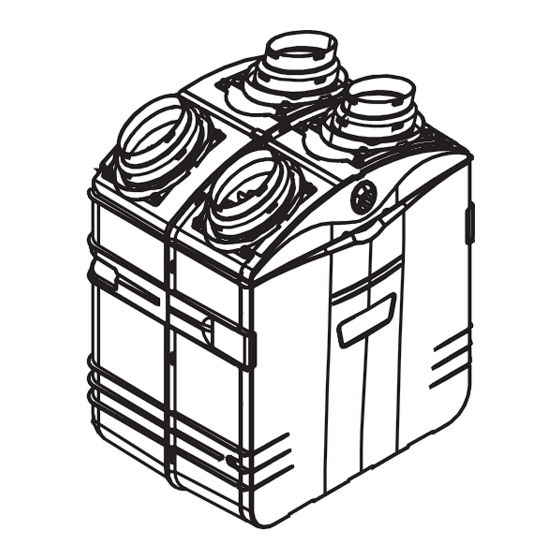
HRV 2500*
HR 2.5*
VB0064
NOTES: 1. HRV 2500* and HR 2.5* models are available in Canada only.
2. HEPA 4000* model is available in United States only.
*Patents pending
HOMEOWNER: USE AND CARE INFORMATION ON PAGES 18 TO 20.
INSTALLATION INSTRUCTIONS
AND USER MANUAL
RESIDENTIAL USE ONLY
READ AND SAVE THESE INSTRUCTIONS
INSTALLER: LEAVE THIS MANUAL WITH THE HOMEOWNER.
M O D E L S
HEPA 4000*
HEPA 3000*
HF 3.0*
04313
rev. F
Advertisement
Table of Contents


Need help?
Do you have a question about the HRV 2500 and is the answer not in the manual?
Questions and answers
Quel filtre je dois mettre dans un vendra HRV 2500
The Venmar HRV 2500 does not have a prefilter. It uses a washable foam filter with a MERV 8 rating.
This answer is automatically generated