Table of Contents
Advertisement
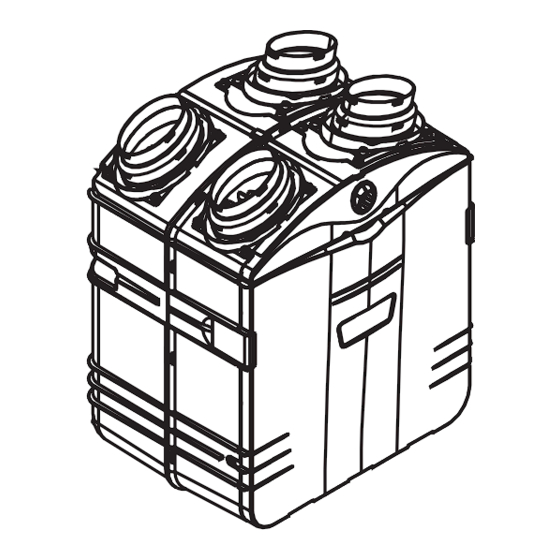
HRV 2500*
HR 2.5*
VB0064
NOTES: 1. HRV 2500* and HR 2.5* models are available in Canada only.
2. HEPA 4000* model is available in United States only.
*Patents pending
HOMEOWNER: USE AND CARE INFORMATION ON PAGES 18 TO 20.
INSTALLATION INSTRUCTIONS
AND USER MANUAL
RESIDENTIAL USE ONLY
READ AND SAVE THESE INSTRUCTIONS
INSTALLER: LEAVE THIS MANUAL WITH THE HOMEOWNER.
M O D E L S
HEPA 4000*
HEPA 3000*
HF 3.0*
04313
rev. F
Advertisement
Table of Contents

Related Manuals for Venmar HEPA 4000


Summarization of Contents
Typical Installations
HRV 2500, HR 2.5, HEPA 3000, HF 3.0 and HEPA 4000 Unit Installations
General installation overview for various HRV, HEPA, and HF models.
Stand Alone Installation
Describes the stand-alone setup for stale and fresh air exchange.
Central Draw Point Installation
Details connecting the unit to a forced air system's return.
Return-to-Return Installation
Explains connecting to a forced air system's return via a second point.
HEPA 4000 Geographical Location
Details geographical considerations for HEPA 4000 unit placement.
HEPA 4000 Attic Installation
Explains attic installation specifics for the HEPA 4000 unit.
Dimensions
HRV 2500 and HR 2.5 Units Dimensions
Provides physical dimensions for HRV 2500 and HR 2.5 models.
HEPA 3000, HF 3.0 and HEPA 4000 Units Dimensions
Provides physical dimensions for HEPA 3000, HF 3.0, and HEPA 4000 models.
Mounting and Servicing Considerations
Details required clearances for unit mounting and servicing.
Before Starting
Inspect Box Contents
Instructions for checking unit components after unboxing.
Tools, Materials, and Installation Kits
Lists necessary tools, materials, and specific installation kits.
Unit Location Considerations
Guidance on selecting an appropriate location for unit installation.
Wall Control Installation
Determine Location and Dimensions
Steps to find the best location and understand control dimensions.
Splice and Connect Wires
Instructions for preparing and connecting control wires to terminals.
Mount the Wall Control
Procedures for physically mounting the wall control unit.
Connect Cable to Unit
Details running the cable and connecting it to the unit's PCB terminals.
Install the Unit
Mount Ports on the Unit
Instructions for attaching the air intake/exhaust ports to the unit.
Hang the Unit
Steps for securely hanging the unit using chains and springs.
Planning of the Ductwork
Guidelines for planning ductwork layout, bends, and lengths.
Installing Non-Insulated Ducts and Registers
Covers installing non-insulated ducts for Stand Alone, Central Draw Point, and Return-to-Return systems.
Installing Insulated Flexible Ducts
Covers connecting insulated flexible ducts to transitions and ports.
Installing Dual Exterior Hood
Details the assembly, location, and connection of the exterior hood.
Connecting the Drain
Instructions for connecting the unit's drain and forming a water trap.
Controls
Main Switch Operation
Explains the function of the 3-position main switch.
Wall Control Overview
Identifies the included wall control models (C34/CMR).
C34 / CMR Control Operation
Details the indicators and functions of the control panel.
Maintenance
Biannual Maintenance Essentials
Steps for biannual maintenance when filter light flashes.
Annual Maintenance Essentials
Steps for annual maintenance when filter light stays on.
Master Reset for Controls
Procedure for resetting maintenance indicators via the control.
Need help?
Do you have a question about the HEPA 4000 and is the answer not in the manual?
Questions and answers