
Related Manuals for Chamberlain Icon26 series


Summary of Contents for Chamberlain Icon26 series
- Page 1 The Chamberlain Group, Inc. 845 Larch Avenue Elmhurst, Illinois 60126-1196 www.liftmaster.com IC O N 2 6 S ER I ES TELEPHONE ENTRY SYSTEM OWNER’S MANUAL www.liftmaster.com...
-
Page 2: Table Of Contents
TABLE OF CONTENTS Product Overview ................3 Resident Use . - Page 3 Icon Page...
-
Page 4: Product Overview
PRODUCT OVERVIEW STANDARD FEATURES • Twenty Six line Large LC Directory. • 32-Device zone control: – Names listed on Directory in alphabetical order. – 32 programmable “Groups”. – 10” LCD screen Sunlight readable and backlit for low light – 32 programmable 7-day timer “Templates”. applications. -
Page 5: Resident Use
RESIDENT USE The Icon26 System will start and default back to the “Welcome To” screen (fig a.). (fig a.) Use the button for assistance. (fig b.). (fig b.) Use the keys to access the residence list in the Icon26’s electronic directory as shown in (fig c.). The names are listed in alphabetical order by last name. - Page 6 RESIDENT USE CONTINUED When the desired name is found, enter the corresponding STATUS 3-digit code. The system will dial the number assigned to the resident code entered. (fig d.) (fig d.) After connecting, the screen will display the “Talk Time” STATUS screen as shown in (fig e.) If the resident wants to allow access to the visitor, they simply press (or dial) “9”...
- Page 7 RESIDENT USE CONTINUED Entry 1 – Entry 2 – Vehicular Gate Door or Pedestrian Gate By pressing or dialing the number “9” on their digital By pressing or dialing the number “5” on their digital or rotary phone, or rotary phone, The resident will open the vehicular entrance gate.
- Page 8 RESIDENT USE CONTINUED If an incorrect key code is entered, the system will STATUS inform the user of the invalid entry (fig b.) The resident can then re-enter their key code. (fig b.) EXAMPLE - KEY CODE 002543 = INDIVIDUAL UTILITY CODES STATUS All systems, no matter what the memory capacity, are equipped with 60 different Utility codes.
-
Page 9: Icon26 Features (Inside)
Icon26 FEATURES (INSIDE) Large Display Contrast Adjustment Large Display Power Switch Camera Power (Optional) Backup Microphone Unit Processor Power Processor Key Mounting Cooling Holes (4) Switch Release / Lock Memory Card Release Buttons Memory Card Memory Card Slot Knock-Out LC Display AC DC Processor POWER N... -
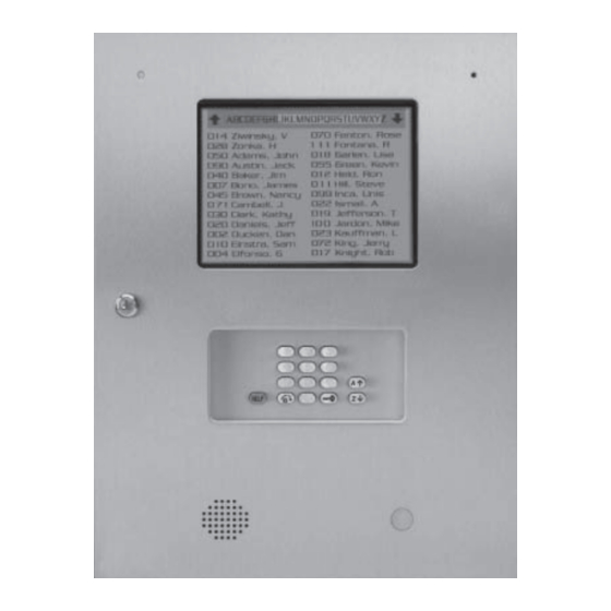
Page 10: Icon26 Features (Outside)
Icon26 FEATURES (OUTSIDE) EXTERNAL MICROPHONE KEY LOCK - Opens the Processor Con- tainment Box to access the Processor. HELP KEY - With digital voice messages to help guide the user. EXTERNAL SPEAKER DISPLAY WINDOW - Heavy-duty, protec- tive lens. KEYPAD LIGHTING Lights dialing keys for easy visibility. -
Page 11: Icon26 Features (Processor)
Icon26 FEATURES (PROCESSOR) MEMORY CARD - Stores all programmed information. (Different memory sizes available) Remote Access RS485 COMMUNICATOR CARD COMMUNICATOR CARD - Card for RS485 devices. capacity POWER ON/OFF SWITCH CARD RELEASE BUTTONS - Eject Cards when pressed. MAIN MEMORY CARD SLOT - Holds Main Memory Card. -
Page 12: Mounting Installation
" 16" Be sure to read and follow all LiftMaster Elite instructions before installating and operating any LiftMaster Elite products. LiftMaster Elite is not responsible for improper installations or failure to comply with local building codes. All components and specifications are subject to change without notice. -
Page 13: Description Of Surge Suppression Terminal Board
DESCRIPTION OF SURGE SUPPRESSION TERMINAL BOARD Knockout for Incoming Wires AC/DC Removable Screw Terminal Connectors for Easy Wiring. OUTPUT RELAYS INPUT POWER IN AUX OUTPUT RELAYS/AUX INPUT: Inputs can be used for Postal Lock and/or Exit switch operations. VIDEO RS-485 (3) RS-485 (1) Auxiliary Input 1-IN activates auxiliary Relay 1 Auxiliary Input 2-IN activates auxiliary Relay 2... -
Page 14: Grounding The Unit
GROUNDING THE UNIT AC/DC OUTPUT RELAYS NPUT POWER N VIDEO RS 485 3) RS 485 (1) TEL L NE N GATE DOOR RE A R LAY Chassis Ground RS 485 4) RS 485 (2) HASS S ROUND CAMERA AUX 1 AUX 2 GATE DOOR... -
Page 15: Earth Ground Rod Installation
EARTH GROUND ROD INSTALLATION Proper grounding gives an electrical charge, such as from an electrical static discharge or a near lightning strike, a path from which to dissipate its energy safely into the earth. Without this path, the intense energy generated by lightning could be directed towards the Telephone Entry System. Although nothing can absorb the tremendous power of a direct lightning strike, proper grounding can protect the Telephone Entry System in most cases. -
Page 16: Basic Wiring Diagram
BASIC WIRING DIAGRAM RING Transformer 12 Vac (50VA) Telephone Line: (Provided) AC/DC MUST be a dedicated line for the OUTPUT RELAYS INPUT Telephone Entry System unit POWER IN ONLY! NOTE: Installation where Polarity does not matter fiber optic phone lines are present 12 Vac 16.5 Vac may require additional... -
Page 17: Power-Up Icon26
3. To turn unit off, turn off both processor and large display battery back-up module. Be sure to read and follow all LiftMaster Elite instructions before installing and operating any LiftMaster Elite products. LiftMaster Elite is not responsible for improper installations or failure to comply with local building codes. -
Page 18: Postal Lock Installation
POSTAL LOCK INSTALLATION These parts are used only when postal access to your facility is required. The postal lock mechanism must be obtained by application to your local post office. Postal Lock Switch Assembly Stainless Steel Front Panel of Entry Phone Switch Assembly Mounting Holes Postal Lock... -
Page 19: Rs485 Wiring Configurations
RS485 WIRING CONFIGURATIONS “Daisy Chain” Configuration #1 wiring configuration (Recommended method for superior data transmission) • Up to 31 RS485 devices supported • Maximum distance from the last RS485 device to the Telephone Entry System is 4000 Ft. • Turn “ON” the terminator switch ONLY for the last device installed in the RS485 line. •... -
Page 20: Rs485 Daisy Chain Connection Example
RS485 DAISY CHAIN CONNECTION EXAMPLE Remote Access RS485 COMMUNICATOR CARD AC/DC capacity OUTPUT RELAYS INPUT POWER IN VIDEO RS485 (3) RS485 (1) TEL LINE IN GATE DOOR RELAY RELAY RS485 Card Release Button RS485 (4) RS485 (2) CHASSIS GROUND CAMERA POSTAL EXIT SWITCH... -
Page 21: Rs485 Star Connection Example
RS485 STAR CONNECTION EXAMPLE Remote Access RS485 COMMUNICATOR CARD AC/DC OUTPUT INPUT capacity POWER IN VIDEO RS485 (3) RS485 (1) NE IN GATE DOOR RELAY RELAY RS485 (4) RS485 (2) RS485 Card Release Button CHASSIS GROUND CAMERA POSTAL SWITCH RELA NOTE: To support RS485 devices you must insert the RF communicator card in the RS485 memory... -
Page 22: Memory Card Installation
MEMORY CARD INSTALLATION Turn power on and insert Memory Card into Main Mem- Main Memory Card Release Button ory Card Slot (Main Memory Card in back slot, Backup Memory Card in front slot.) (fig a.) Push it all the way in until card “snaps”... -
Page 23: Warning And Precautions
WARNINGS AND PRECAUTIONS Do not touch the terminals on the RAM Cards. Do not bend, drop or expose to impact. The Telephone Entry System is only water resistant when the Stain- less Steel Door is closed and locked. Do not expose the Processor Unit or the open Processor Containment Box to rain, snow, or harsh weather conditions. -
Page 24: Programming The Processor
PROGRAMMING THE PROCESSOR ENTERING THE PROGRAM MODE When the Processor unit is turned on and the button is pressed, the screen will display: TO ENTER PROG MODE, Type Password >____ Type in the factory present password (7777). Press . The Program Selection Screen will display: SELECT PROG MODE: (N)Names (U)Utility... -
Page 25: Selecting Program Mode
SELECTING PROGRAM MODE LIST OF PROGRAM MODES: Program or edit Resident Names Names page 25-27 Program or edit Utility Codes Utility page 28 Program New Password ( recommended ) page 29 Password* Program System Clock and Seven Day Timers Clock/Timer pages 30-32 Program relay output time ( for 2 relays ) Strike Time... -
Page 26: Resident Information
RESIDENT INFORMATION In the Program Selection Screen (fig a.), Press the key. The screen will display (fig b.): STEP SELECT PROG MODE: PROG A NEW NAME (N)Names (U)Utility PROG BY CODE:___ (fig a.) (fig b.) STEP You now have three options: To program by name, press To program by code, enter To view or edit an existing name... -
Page 27: Transmitter/Card Programming
TRANSMITTER/CARD PROGRAMMING STEP To complete entry, press the key to return to the program selection screen. To program RF devices ( i.e. transmitters/cards etc.) continue on to Step 7. NOTE: To enable the transmitter/card programming feature, you must insert the communicator card in the “backup”... -
Page 28: Area Codes
AREA CODES 005 PHONE NUMBER: _-___-___-____ (fig a.) PREFIX FIELD AREA CODE FIELD In special applications, it is necessary to enter area codes for Resident Phone Numbers. Area codes are entered from the Phone Number screen (fig a.). 005 PHONE NUMBER: 1-___-___-____ (fig b.) Use the... -
Page 29: Utility Codes
UTILITY CODES A 4-digit Utility Code (numeric characters only) may be assigned to “Utility Companies” such as delivery, telephone, con- struction companies, water, power, etc. These utilities can use their individual code to access the premises within the time zone that you program. Each system, no matter what the memory capacity, is equipped with 60 available Utility Codes and time zones. -
Page 30: Password
PASSWORD The factory present password is 7777. We suggest that you customize it. In the Program Selection Screen (fig a.), Press the SELECT PROG MODE: key. (P)Password (fig a.) To customize a password, type in a four character password (it may be alphanumeric characters). NEW PASSWORD: Press the key to enter the new... -
Page 31: Clock/Timer
CLOCK/TIMER The Clock/Timer allows you to set the date and time, and to program gates and doors to be opened or closed whenever specified. This clock is equipped with 100 year calender, auto leap year compensation and daylight savings. In the Program Selection Screen (fig a.), Press the SELECT PROG MODE: key. - Page 32 CLOCK/TIMER CONTINUED 2./ 3. DOOR AND GATE TIMERS Press to program Gate Timers Menu. Press to program the Door Timers Menu. Setup New Timers> N See next page for instructions USE ARROWS TO VIEW / PROGRAM View/Edit Timers> INDIVIDUAL TIME ZONES SUN G Tmr1: ON F=off to view and program timer(s) for Sunday through Saturday.
-
Page 33: Clock/Timer
CLOCK/TIMER CONTINUED 2./ 3. DOOR AND GATE TIMERS, continued’ Press to program Gate Timer Menu Press to program the Door Timers Menu PRESS TO PROGRAM SETS OF Setup New Timers> N TIME ZONES View/Edit Timers> See previous page for instructions Program timers 1 and 2 for any day of the week (fig d.) GATE Tmr1: ON F=off __:__am ->... -
Page 34: Strike Time
STRIKE TIME Strike Time sets the amount of time your gate or door relay will be held open. In the Program Selection SELECT PROG MODE: Screen (fig a.), Press the (S)Strike Time key. (fig a.) The strike time can be set for Door Strike Time >... -
Page 35: Greeting
GREETING Use the Greeting Screen to customize the Welcome message. SELECT PROG MODE: In the Program Selection Screen (fig a.), Press key. (G)Greeting (fig a.) Type the name of the facility and press the FACILITY NAME: key to complete your entry. The Woodbridge Meadows system will automatically center your entry on the Welcome screen.(fig b.) -
Page 36: Back-Up Memory
BACK-UP MEMORY Back-Up Memory Card Release Button (fig a.) NOTE: You must have an extra memory card (sold separately) installed in the RS 485 Slot (fig a.) of the Processor in order to perform the backup process. SELECT PROG MODE: In the Program Selection Screen (fig b.), Press the key. -
Page 37: Error Messages
ERROR MESSAGES OUT OF RANGE CODES: If the processor detects one Codes Detected out or more 3-digit codes present on the memory card inserted that cannot be accessed, an error message is of Range, See Manual displayed. (fig a.) Codes that cannot be accessed by the limitation of the system being used cannot be (fig a.) edited. -
Page 38: Display Controller Board
DISPLAY CONTROLLER BOARD Display Contrast Adjustment Power Input Battery Overvoltage BATT OVRV Power BUSY Power POWER 12 VAC Input 12 VAC Output - (Not used) Battery - (On/Off switch input) Input/Output Comm Port - (Connected to processors parallel port) Sensor Input Large Display Contrast Adjustment - (Clockwise-Lighter Contrast, Counterclockwise-Darker Contrast) ON: System is working using battery power. -
Page 39: Large Display Battery Back-Up
LARGE DISPLAY BATTERY BACK-UP OVRV BUSY T-100 is a built-in battery back-up module for the Large Display Controller Board. It provides the system with 3 to 5 hours of battery operation. NOTE: “LCD Power” switch must always be turned ON for large display to operate. Icon Page... -
Page 40: Auxiliary Input/Output
AUXILIARY INPUT/OUTPUT CONNECTIONS Input 2 Postal Lock Connection Example Input 1 Exit Switch Connection Example AC/DC OUTPUT RELAYS INPUT POWER IN VIDEO RS-485 (3) RS-485 (1) TEL LINE IN GATE DOOR RELAY RELAY RS-485 (4) RS-485 (2) CHASSIS GROUND CAMERA POSTAL EXIT SWITCH... -
Page 41: Optional Camera
OPTIONAL CAMERA Part # ICON26CAMERA This compact, optional color camera is only 22 mm x 26 mm and is capable of 10-bit DSP, 330 line resolution output. Connect camera to surge suppression terminal board with cable supplied with camera. Connect a BNC cable from a time lapse recorder or monitor to the Video Out connector on the surge suppression terminal board. -
Page 42: Parts List And Part Illustrations
PARTS LIST AND ILLUSTRATIONS T109 T010 T103 T111 T135 Icon T150SPT Camera T011 T180 Remote Access RS485 COMMUNICATOR CARD capacity T104 Memory RS485 Card Card T106 T020 T148 T030 T003 T027 LC Processor T029 AC/DC OU PUT RELAYS NPUT POWER N VID O RS 85 3) RS4 5 1) -
Page 43: Approvals
APPROVALS The Chamberlain Group, Inc. Complies with Part 68, FCC Rules UL STD 294, 5th Ed. FCC Part 15 - Tested to comply with UL STD 1950, 3rd Ed. FCC standards for home or office use This Class B digital apparatus meets all requirements of CANADIAN Interference Causing Equipment Regulations. - Page 44 © 2011, The Chamberlain Group, Inc. 114A2894F All Rights Reserved...
Need help?
Do you have a question about the Icon26 series and is the answer not in the manual?
Questions and answers