Chamberlain EL25 Installation
Telephone entry/access system
Hide thumbs
Also See for EL25:
- Programming manual (69 pages) ,
- Installation manual (30 pages) ,
- Quick start manual (26 pages)
Advertisement
Available languages
Available languages
Quick Links
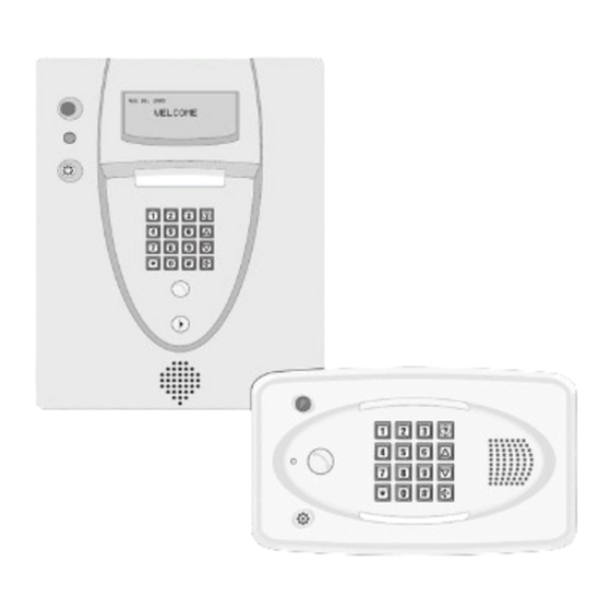
Telephone Entry/Access Control System
Models EL25 and EL2000SS
RESIDENTIAL AND COMMERCIAL TELEPHONE ENTRY SYSTEMS
WITH EXPANDED CAPACITY AND ENHANCED VERSATILITY
Optional modules let you expand the system to fi t your specifi c needs. The Wiegand output module lets you add card readers and/or remote
keypads. Our RF module provides convenient access through gates or doors with Passport™ transmitters. Plus, the system is now designed to
automatically detect the addition and location of each new plug-in module, making installation and programming faster and easier than ever before.
EL2000SS
EL25
Wiring
CONNECTING TO THE TELCO LINE
The bypass board allows the unit(s) to be disconnected without interrupting
Disconnect power at the fuse box BEFORE proceeding. The unit
normal telephone operation. If the unit(s) will be used in conjunction with an
MUST be properly grounded and connected in accordance with
alarm system, you must connect the telephone line to the alarm system fi rst.
national and local electrical codes. NOTE: The unit should be on a
If the units are not connected in this order, they will not operate properly.
separate fused line of adequate capacity.
Up to 7 units can share the same phone line. You must program the unit ID
• A static discharge can damage circuit boards
for each unit wired in the series. See Keypad Programming manual.
• NEVER run telco wires and high voltage wires in the same
The bypass board (located inside the property) allows access to the phone in
conduit. The high voltage may interfere with the telco wires,
case the unit(s) fail.
possibly causing the system to malfunction.
NOTE: Installation where fi ber optic phone lines are present may require
additional modifi cations from your telephone provider. Contact your provider
for more information.
• When a unit is in use, the bypass switch must be set to the
operate position.
• To AVOID damaging gas, power or other underground utility
• When a unit is disconnected, the bypass switch must be set to the
lines, contact underground utility locating companies BEFORE
bypass position.
digging more than 18 inches (46 cm) deep.
• Contact the building inspector's offi ce in the municipality where
you plan to install the unit for correct grounding materials and
installation procedures.
• Ensure that the system is grounded properly. The units contain
STAND ALONE SYSTEM
a number of static sensitive components that can be damaged
The unit can be a stand alone system that allows communication between the unit and a
by static discharge.
resident's phone. Connect a twisted wire (18-24 AWG) from the RES terminal block on the
• DO NOT ground the units to a pedestal post (gooseneck) if one
unit's output board, to the resident's phone.
is used.
Up to 7 units can share the same phone line. You must program the unit ID for each unit
wired in the series. See Keypad Programming manual.
GROUND THE UNIT
Only disable the Telco mode of the unit farthest away from the house. See "Disable Telco
Install an earth ground rod no further than 12 feet from the unit and
Mode" in the Keypad Programming manual.
use a minimum of 12 gauge wire in most cases. The type and length
NOTE: Ringer Equivalence Number (REN) of "5" maximum.
of earth ground rods vary by region.
NOTE: Keep ground wire as straight as possible.
ALTERNATIVE GROUNDING SOLUTIONS
The unit may be grounded to a metallic or an
CONNECTING TO A DEDICATED TELCO LINE
existing electrical system within
Installation where fi ber optic phone lines are present may require additional modifi cations from your
12' of the unit.
telephone provider. Contact your provider for more information.
Up to 7 units may be installed. You must program the unit ID for each unit wired in the series.
See Keypad Programming manual.
OR
Green Ground Wire
DSL Modem
12 ft Maximum
Metallic Cold
Water Pipe
Ground Wire
Electrical Panel
CONNECTING TO AN INTERNAL PHONE SYSTEM
Earth Ground Rod
Alternative Grounding Solutions
The units can be wired to any analog trunk in an internal
home phone system.
Installation where fi ber optic phone lines are present may
require additional modifi cations from your telephone
provider. Contact your provider for more information.
LiftMaster
Up to 7 units may be installed. You must program the
845 Larch Avenue
unit ID for each unit wired in the series. See Keypad
Programming manual.
Elmhurst, IL 60126-1196
LiftMaster.com
Installation
The EL25 is for surface mount applications
Mount to a wall or pedestal.
1
4
only. Unlock the unit and open cover.
Carefully lift mounting plate up then slide
out on hinges.
PEDESTAL
Unplug the two main harnesses.
2
OPTIONAL
VERTICAL MOUNTING
Rotate the keypad for vertical
mounting:
1
Disconnect all plugs from the
control board (See illustration).
Remove control board.
2
Remove bracket (4 screws).
3
Rotate keypad 90° clockwise.
Bracket notch lines up with
ribbon cable on the keypad.
4
Reverse the sequence to
reassemble the unit.
5
Reconnect all plugs to the
control board.
Line up notch with screw and push hinge out.
3
Remove the mounting plate from the cover.
Lock the unit. Do not pinch wires when closing
5
and locking the unit.
Bypass Board
Bypass Board
for Unit 1
for Unit 2
Home Phone
Telco Entrance Box
Alarm SystemPosition
Demarcation Point
(Not Provided)
Ring
Ring
Tip
Tip
Tip
Ring
To RES
To TELCO
Unit ID 2
Output Board
Home Phone
Ring
DSL
PHONE
Tip
DSL Filter
(Optional)
Telco Entrance Box
Demarcation Point
Ring
Tip
Internal Phone System
Analog Trunk
EL25
6 in.
3-15/16 in.
10-1/4 in.
3-1/16 in.
3 in.
3-1/16 in.
WALL
Mounting Holes (4)
5-1/8 in.
for 5/16 in.
1-1/16 in.
Conduit Hole
J406 LCD
J201 MIC
J401 KEYPAD
3
Keypad
2
Bracket
J404 LED
1
Main Circuit
Board
J402 LED
J402 SPKR
CONTROL BOARD
To next unit
(Unit ID 5 then Unit ID 4 etc.)
Unit ID 6
For additional
units
Ring
Tip
Use 18-24 AWG
2 twisted pair
Ring
Tip
For additional
units
14-Pin to
Control Board
Unit ID 2
To next unit
(Unit ID 3, then Unit ID 4, etc.)
EL2000SS
The EL2000SS is for fl ush mounted applications. Turn key clockwise
1
and open the cover.
Mount to a wall. Knock out the desired mounting plugs using punch. Make sure the unit is
2
properly sealed to prevent damage to the access control panel from moisture.
11.25 in.
3.5 in.
10.28 in.
.5 in.
14.5 in.
5.625 in.
16 in.
14 in.
16 in.
Conduit Holes
8 in.
1.5 in.
.188 in.
2 in.
1 in.
.75 in.
.485 in.
2 in.
7.25 in.
11-1/4 in.
2.5 in.
1-15/16 in.
Close the cover. Turn the key counter-clockwise
3
to the locked position.
Output Board
3
1
4
5
2
6
TERMINAL BLOCK CONNECTIONS
1
Resident - Tip/Ring
2
Telco - Tip/Ring
3
Relay 4, NO, NC, COM
4
Relay 3, NO, NC, COM
DO NOT overload the
removable terminal
5
Relay 2, NO, NC, COM
block connectors.
One wire per hole.
6
Relay 1, NO, NC, COM
WALL
CONNECTING A GATE OPERATOR
Refer to the gate operator manual for proper relay strike time. Additional
opening or exit devices can be connected to any of the 4 relays.
Normally Open
Common
Use 18-24 AWG
CONNECTING TO A DOOR STRIKE LOCK
The door strike can be connected to any of the 4 relays.
FOR AC POWER: Install a Siemens S10K30 MOV (Metal Oxide Varistor) or equivalent.
FOR DC POWER: Install a 1N4005 diode or equivalent.
DO NOT USE THE UNIT'S POWER SUPPLY FOR THE DOOR STRIKE.
Siemens S10K30 MOV
(Metal Oxide Varistor)
Normally Open
or equivalent.
1N4005 diode
or equivalent.
Common
Use 18-22 AWG
AC or DC Power for
Door Strike (Not Provided)
CONNECTING A MAGLOCK
The maglock can be connected to any of the 4 relays.
FOR AC POWER: Install a Siemens S10K30 MOV (Metal Oxide Varistor)
or equivalent
FOR DC POWER: Install a 1N4005 diode or equivalent.
DO NOT USE THE UNIT'S POWER SUPPLY FOR THE MAGLOCK.
Normally Closed
Siemens S10K30 MOV
1N4005 diode
(Metal Oxide Varistor)
or equivalent.
or equivalent.
Common
AC or DC Power for
Use 18-22 AWG
Door Strike (Not Provided)
Advertisement

Related Manuals for Chamberlain EL25


Summary of Contents for Chamberlain EL25
- Page 1 Installation Models EL25 and EL2000SS EL25 EL2000SS The EL25 is for surface mount applications Mount to a wall or pedestal. only. Unlock the unit and open cover. The EL2000SS is for fl ush mounted applications. Turn key clockwise Carefully lift mounting plate up then slide and open the cover.
- Page 2 Control Board Versa XS 4.0 Software Accessories FCC & DOC Requirements Versa XS 4.0 software allows access control management for the EL2000SS and EL25 with remote programming capabilities for multiple users and FREE Cloud FCC REQUIREMENTS WOMODKT EL25/EL2000SS Wiegand Module storage.
- Page 3 SYSTÈME D’ACCÈS/DE CONTRÔLE D’ACCÈS PAR TÉLÉPHONE Installation EL25 et EL2000SS EL25 EL2000SS Le système EL25 est destiné à être monté Effectuez un montage sur mur en surface seulement. Déverrouillez ou sur piédestal. Le système EL2000SS est pour applications pour assemblage encastré.
- Page 4 Module Wiegand pour modèles EL25/EL2000SS Le logiciel Versa XS 4.0 permet de gérer le contrôle d’accès pour les modèles EL2000SS et EL25 avec capacités de programmation à distance pour de multiples Les unités sont conformes à la section 68 de la réglementation de la FCC. L’étiquette apposée à cet équipement contient, parmi d’autres renseignements, le Prend en charge deux dispositifs compatibles avec Wiegand de 26 ou 30 utilisateurs et stockage GRATUIT dans l’infonuage.
Need help?
Do you have a question about the EL25 and is the answer not in the manual?
Questions and answers