
Subscribe to Our Youtube Channel
Related Manuals for Speco mobile dvr


Summary of Contents for Speco mobile dvr
- Page 1 4 Channel H.264 Mobile DVR User Manual V1.0 Copyright © 2009 Speco Technologies. All Rights Reserved...
- Page 2 2009 Speco Technologies Inc. All rights reserved. This material, information and instructions for use contained herein are the property of Speco Technologies Inc. No part of this manual, including the products and software described in it, may be reproduced, transmitted, transcribed,...
-
Page 3: Package Contents
PACKAGE CONTENTS Prior to installation of the SPECO MOBILE DVR, please verify that the packaging contains the following contents: 1. One DVR 2. One AC Adaptor 3. One Power Cable 4. DVR Viewer Program CD 5. Instruction Manual 6. Two Rack Mount Ears and Four screws 7. -
Page 4: Risk Of Electrical Shock Warning
RISK OF ELECTRICAL SHOCK WARNING WARNING TO REDUCE THE RISK OF FIRE OR ELECTRIC SHOCK, DO NOT EXPOSE THIS PRODUCT TO RAIN OR MOISTURE. DO NOT INSERT ANY METALLIC OBJECTS THROUGH THE VENTILATION GRILLS OR OTHER OPENINGS ON THE EQUIPMENT. CAUTION EXPLANATION OF GRAPHICAL SYMBOLS The lightning flash with arrowhead symbol, within an equilateral triangle, is intended to... - Page 5 DISCLAIMER While every effort has been made to ensure that the information contained in this guide is accurate and complete, no liability can be accepted for any errors or omissions. Maker reserves the right to change the specifications of the hardware and software described herein at any time without prior notice.
-
Page 6: Read This First
Read this First Test Sessions Before you try to record important subjects, we highly recommend that you make several test sessions to ensure that the Digital Video Recorder is operating and being operated correctly. Please note that Maker, its subsidiaries and affiliates, and its distributors are not liable for any consequential damages arising from any malfunction of the Digital Video Recorder or its accessories. -
Page 7: Safety Precautions
SAFETY PRECAUTIONS Before using the Digital Video Recorder, please ensure that you read and understand the safety precautions described below. Always ensure that the Digital Video Recorder is operated correctly. The safety precautions noted on the following pages are intended to instruct you in the safe and correct operation of the Digital Video Recorder and its accessories to prevent injuries or damage to the self, other persons and equipment. - Page 8 Do not allow the equipment to come into contact with, or become immersed in, water or other liquids. Do not allow liquids to enter the interior. The Digital Video Recorder has not been waterproofed. If the exterior comes into contact with liquids or salt air, wipe it dry with a soft, absorbent cloth.
- Page 9 PREVENTING MALFUNCTION Avoid Strong Magnetic Fields. Never place the Digital Video Recorder in close proximity electric motors other equipment generating strong electromagnetic fields. Exposure to strong magnetic fields may cause malfunctions or corrupt image data. Avoid Condensation Related Problems. Moving the equipment rapidly between hot and cold temperatures may cause condensation (water droplets) to form on its external and internal surfaces.
-
Page 10: Table Of Contents
Table of Contents ABOUT THIS MANUAL ............... 12 FEATURES AND SPECIFICATIONS ........... 12 FEATURES ....................13 SPECIFICATIONS ..................14 OVERVIEW & CONTROLS ............17 FRONT PANEL ..................... 17 REAR VIEW ....................18 IR REMOTE CONTROLLER ..............18 MOUSE CONTROLLER ................21 MAIN SCREEN ................ - Page 11 4.2.2.10 SPEED DISPLAY MODE ......................33 4.2.3 TITLE ..........................34 4.2.4 COVERT ........................... 35 4.2.5 CAMERA .......................... 35 RECORD ....................36 4.3.1 RECORD SETUP ......................36 4.3.2 RECORD PROGRAM ...................... 36 4.3.3 PREVIEW QUALITY ......................37 4.3.4 AUDIO RECORD ......................38 4.3.5 REPEAT RECORD ......................
- Page 12 4.6.4 E-MAIL ..........................67 4.6.4.1 SEND E-MAIL..........................67 4.6.4.2 SMTP SETUP ..........................68 4.6.4.2.1 SMTP SERVER ........................68 4.6.4.2.2 SMTP PORT ........................68 4.6.4.3 DVR E-MAIL ADDRESS ......................68 4.6.4.4 USER ID AND PASSWORD ....................... 68 4.6.4.5 E-MAIL ADDRESS 1 THROUGH 10 ..................... 68 4.6.5 DVR NAME ........................
-
Page 13: About This Manual
ABOUT THIS MANUAL This is the Instruction Manual for H.264 Mobile Digital Video Recorder for the SPECO MOBILE DVR, This Manual depicts the user how to install and operate the DVR provided with the features and specifications. Please read this manual carefully and follow the installation procedure before using the system. -
Page 14: Features
RS-485 port for PTZ & External Controller support. Driving Information (warning lights, brakes, turn signals) overlay on live and playback video. GPS (optional) data can overlay location & speed and record with video for Mobile DVR. Impact Sensor (optional) detects excessive gravitational forces on X,Y,Z axis. -
Page 15: Specifications
1.2 Specifications VIDEO Video Input 4CH (BNC) 1.0Vp-p±10% Composite, 75Ω Balanced Input Level Loop Through Output Not supported Video Standard NTSC, PAL, AUTO 1.0 Vp-p Composite, 75Ω Balanced Main Monitor Output Analog Spot Monitor Output Not supported Camera Name Max. 8 Characters Screen Split Control 1, 4 Screen Screen Rotate Control... - Page 16 1 port in front Copied File Compatibility with Compatible PC (Windows) MULTI-REMOTE SURVEILLANCE Monitoring Environment Client software / CMS for mobile DVR / SD viewer Transmission Rate Max. 120ips(CIF) full motion transmission Search Supporting multi-client(16 clients accessible) SYSTEM MONITORING & RECOVERY...
- Page 17 Connector Video Input 4CH (BNC) Loop Though Not Supported Composite Supported Main Monitor Output VGA Output Supported Spot Monitor Output S-Video Not Supported Audio Input ( Line) 1CH (RCA) Audio Output ( Line) 1CH (RCA) HDD Bay Connection 1CH Line Output (RCA) External Control ( RS-232C) Not Supported Firmware Update...
-
Page 18: Overview & Controls
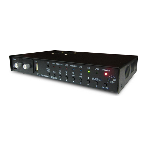
2. OVERVIEW & CONTROLS This section provides the information about the front panel and rear panel. 2.1 Front Panel Function ① Power switch This switch turns the DVR on or off. ② SD CARD The Image can be stored by SD memory card, Max. 2 SD card. ①... -
Page 19: Rear View
2.2 Rear View Function ① Detect the speed and the direction. GPS ANT. ② RCA Connectors for Composite Video Signal Input. Camera Input ③ RCA Connectors for connecting the Audio Input. Audio Input ④ RCA Connectors for connecting the Audio & Video Output. Audio &... -
Page 20: Remote Control
Button Name Description 2.3 Remote Control ○ REMOTE REMOTE CONTROLLER ID in the system CONTROLLER ID setup ○ Iris close and open of PTZ / ○ (IRIS-/+) Frame by Frame(field by field) playback ○ (ZOOM-/+) Zoom in and out of PTZ Enter the spot mode / Return to the ○... -
Page 21: Mouse Control
○ LV/PB ( Convert the screen into real display mode during the playback ○ DIR ( Change the direction of playback ○ RECORD ( Begin and stop recording ○ MULTI Display multi-screen ○ TEXT Reserved ○ AUDIO SELECT Audio select button ○... -
Page 22: Mouse Controller
MAIN SCREEN 1. REMAINING HARD DRIVE SPACE / PLAYBACK STATUS The remaining hard drive space is displayed either in percentage or in Gigabytes. If the hard drive overwrite is set to on, the counter will remain as 0 and the DVR will continue to write on to the hard drive from the beginning. - Page 23 5. CHANNEL INFORMATION The channel information is displayed. When the channel is in normal recording mode, it will display the channel title as entered by the user. When the channel is in event recording mode, it will display the appropriate event recording mode: alarm, motion, video loss and GPS. 6.
-
Page 24: Main Menu
MAIN MENU Before operating the DVR, please make sure that you have properly connected all the cables and storage devices. By pressing the Menu button on the DVR or using the Remote controller let the below screen pops-up. 4.1 QUICK SETUP Quick setup enables the user to quickly setup major recording settings of the DVR. -
Page 25: Image Size
4.1.2 IMAGE SIZE Select the desired IMAGE SIZE for recording as shown below by pressing the button. The default size is Half D1. NTSC 720 X 480 (D1) 720 X 576 (D1) 720 X 240 (Half D1) 720 X 288 (Half D1) 360 X 240 (CIF) 360 X 288 (CIF) 4.1.3 RECORD FRAME... -
Page 26: Image Quality
4.1.4 IMAGE QUALITY Select the desired image quality using the button. There are 4 kinds of image quality like Best, Fine, Normal and Low. The default is “NORMAL”. 4.1.5 EVENT User can select any type of EVENT by using the button, it is possible to select among “ALL”, “ALARM”, “V-LOSS”, “MOTION”, “GPS”, “ALARM&LOSS”, “ALARM&MOTION”,... -
Page 27: Pre Record Time
4.1.6 PRE RECORD TIME Select the desired time for pre-recording using button from the remote. When video loss, alarm or motion is detected, the DVR will store pre-recorded data during the selected time. The pre-recording time can be set up from 0 second to 5 second and the default is “0 seconds”. -
Page 28: Audio Record
4.1.9 AUDIO RECORD Select “ON” or “OFF” using the button of the remote to record audio for all channels. The default is “OFF”. 4.1.10 SAVE Press the Save icon using the Enter button in order to save the Menu Configuration. 4.2 SCREEN Screen setup defines various screen related options. -
Page 29: Auto Sequence
4.2.1 AUTO SEQUENCE At the SCREEN menu, Move the cursor to the AUTO SEQUENCE ▲,▼ using buttons. Press the ENTER button when the cursor is on the AUTO SEQUENCE and the following screens appears. ▲,▼ Move the cursor to each single or split channel using the buttons. -
Page 30: Storage Free Space
4.2.2.1 STORAGE FREE SPACE At the DISPLAY menu, ▲,▼ Move the cursor using the buttons to select the STORAGE FREE SPACE. button to choose “ON” or “OFF”. Press The default is “ON”. ON: Remaining capacity of the fixed (not backup) SD will be displayed on the screen. 4.2.2.2 STORAGE FREE SPACE MODE At the DISPLAY menu, ,▼... -
Page 31: Record Status
4.2.2.3 RECORD STATUS At the DISPLAY menu, ▲,▼ Move the cursor using the buttons to select the RECORD STATUS. button to choose “ON” or “OFF”. Use the The default is “ON”. ON: Displaying the recording status of each channel on the screen. 4.2.2.4 CLOCK DISPLAY At the DISPLAY menu, ▲,▼... -
Page 32: Date & Time Mode
4.2.2.5 DATE & TIME MODE At the DISPLAY menu, ▲,▼ Move the cursor using the buttons to select the DATE&TIME MODE. button to choose “YY/MM/DD” or Use the “MM/DD/YY” or ” DD/MM/YY”. The default is “MM/DD/YY”. YY/MM/DD : All date and time will be displayed in numbers. Ex. -
Page 33: Title Mode
4.2.2.7 TITLE MODE At the DISPLAY menu, ▲,▼ Move the cursor using the buttons to select the TITLE MODE. button l to choose “TEXT” or Use the “BITMAP”. The default is “TEXT”. A bitmap is a type of graphics file on a computer. You can make characters with bitmap on the setup window of network client viewer after connecting the computer with DVR. -
Page 34: Gps Information
4.2.2.9 GPS INFORMATION At the DISPLAY menu, ▲,▼ Move the cursor using the buttons to select the GPS INFOMATION. button to choose “ON” or “OFF”. Use the The default is “ON”. ON: When the GPS INFORMATION is made “ON”, it gives the tracking information about the vehicle. -
Page 35: Title
4.2.3 TITLE At the SCREEN menu, ▲,▼ Move the cursor to the TITLE using buttons. Press the ENTER button to access the title submenu. At this menu, users can create the title of channel. Press the enter button to edit the channel title. Press the ENTER button after selecting desired channel using the ▲,▼... -
Page 36: Covert
4.2.4 COVERT At the SCREEN menu, Move the cursor to the COVERT using the ▲,▼ buttons. Press the ENTER button when the cursor is on the COVERT and the screen appears. Move the cursor and select the desired item ▲,▼ using the buttons. -
Page 37: Record
4.3 RECORD To set up the RECORD menu, Move the cursor to the RECORD icon using the ◀, ▶ in the MENU screen. Press the ENTER button when the cursor is on the RECORD icon and the following items appear. User can select any item using ▲,▼... -
Page 38: Preview Quality
recording schedule on the RECORD SETUP menu. For example, you can create a program for Motion detection or continuous recoding At the RECORD menu, Move the cursor to the RECORD PROGRAM using ▲,▼ buttons. Press the ENTER button when the cursor is on the RECORD PROGRAM and the following screen appears. -
Page 39: Audio Record
Select the desired RECORD QUALITY using the button among “NORMAL”, “FINE”, “BEST” and “LOW”. And you can see the size of each image quality and how long you can record in the installed HDDs by the image quality. To exit this PREVIEW QUALITY menu, press the ESC button. -
Page 40: Repeat Record
4.3.5 REPEAT RECORD At the RECORD menu, Move the cursor to the REPEAT RECORD using ▲,▼ buttons. Press the ENTER button when the cursor is on the REPEAT RECORD and the following screen appears. button to set “ON” or “OFF”. Use the It is possible to set a point of time to work the REPEAT RECORD ALARM. -
Page 41: Holiday
4.3.6 HOLIDAY At the RECORD menu, ▲,▼ Move the cursor to the “HOLIDAY” using buttons. Press the “ENTER” button to set up “HOLIDAY” and the HOLIDAY menu screen appears. Set up “ON” or “OFF” of HOLIDAY RECORD using the button. ▲,▼... -
Page 42: Event
4.4 EVENT Event setup defines various event options such as the motion grid and the motion detection sensitivity, the main screen event response option, sensor input and relay output options. 4.4.1 MOTION DETECTION At the EVENT menu, Move the cursor to the MOTION DETECTION ▲,▼... -
Page 43: Sensitivity
4.4.1.2 SENSITIVITY At the MOTION DETECTION menu, ,▼ Move the cursor to SENSITIVITY using ▲ buttons. Select the sensitivity level from 1 to 5 using the button. The default is “5”. SENSITIVITY: The higher the number is, the more sensitive. 1(lowest) ~ 5(highest) 4.4.1.3 AREA SETUP At the MOTION DETECTION menu, ▲,▼... -
Page 44: Test Motion
4.4.1.4 TEST MOTION At the MOTION DETECTION menu, Move the cursor to TEST MOTION using the ▲,▼ buttons. Press the ENTER button to test the motion detection. To exit this TEST MOTION, press the ESC button. Any grid that detects motion will flash a purple tint for the period of time that it detects motion. -
Page 45: Event Check
4.4.3 EVENT CHECK At the EVENT menu, Move the cursor to the EVENT CHECK using ▲,▼ buttons. Select “ON” or “OFF” using the button. 4.4.4 EVENT INDICATION At the EVENT menu, Move the cursor to the EVENT INDICATION ,▼ using ▲ buttons. -
Page 46: Relay Output
▲,▼ Select the desired channel using the buttons. Select the type of sensor which is connected with DVR using the button. To exit this SENSOR INPUT menu, press the ESC button. Select the right sensor type according to the type of installed sensor with the unit. NORMAL OPEN : The sensor is open in normal times. -
Page 47: Gps
NOTE: It is possible to set the RELAY OUTPUT in the type of event, and it is possible to set the period of the relay output from 1 to 30 seconds. <RELAY SELECT> There are POWER (N.C), USER, REC, NOT USED, ALARM, LOSS, MOTION and HDD ERROR, you can select one type among the above 8 menu. -
Page 48: System
X-THRESHOLD: X-Threshold values are automatically varied when there is any event but the default value is 1. Y-THRESHOLD: Y-Threshold values are automatically varied whenever any event occurs but the default value is 0. Z-THRESHOLD: Z-Threshold values also changes when any event occurs but the default value is 4. SPEED PARAMETER: The below said parameter values may change depending on the acceleration speed of the vehicle. -
Page 49: Storage Configuration
4.5.1.1 STORAGE CONFIGURATION At the STORAGE menu, Move the cursor to STORAGE CONFIGURATION using the ▲,▼ buttons. Press the ENTER button when the cursor is on the STORAGE CONFIGURATION and the following screen appears. User can set the SDCARD Memory stick either to Record or Backup Mode arbitrarily. -
Page 50: Storage Initialize
4.5.1.2 STORAGE INITIALIZE At the STORAGE menu, Move the cursor to STORAGE INITIALIZE using the ▲,▼ buttons. If you want to initialize the STORAGE, move the cursor to “YES” and then press the “ENTER” button. If not, move the cursor to “NO” and then press the “ENTER”... -
Page 51: Date&Time
4.5.2.1 DATE&TIME At the CLOCK menu, Move the cursor to the DATE&TIME using the ▲,▼ buttons. Press the ENTER button when the cursor is on the DATE&TIME and the following screen appears. ▲,▼ Use the buttons to move the cursor to the desired position of date or time. -
Page 52: Video Standard
Use the ▲,▼ buttons to move the cursor and use the (-), (+) buttons to change the value. To exit this TIME ADJUST menu, press the ESC button. Manual setup: This DVR can recognize the correct time by itself. That is to say, if you input the correct time 3 or 4 times, the DVR will recognize the clock error and display the correct time by itself. -
Page 53: Key Echo
4.5.5 KEY ECHO At the SYSTEM menu, Move the cursor to the KEY ECHO using the ,▼ ▲ buttons. Select the “ON” or “OFF” using the button. ON: The beep sounds when you press any buttons on the front panel. OFF: The beep does not sound. -
Page 54: Power Off Voltage
4.5.6.1 POWER SAVING TIME Select “ON” or “OFF” using the button , if user selects POWER SAVING TIME “ON”, the DVR will not power off during the set up time. User can select the power saving time from 10 to 990 minutes. 4.5.6.2 POWER OFF VOLTAGE Select voltage rate using the button from... -
Page 55: Advanced Setup
4.5.7 ADVANCED SETUP At the SYSTEM SETUP menu, Move the cursor to the ADVANCED SETUP ▲,▼ using the buttons. Press the ENTER button when the cursor is on the ADVANCED SETUP and the following screen appears. To exit this ADVANCED SETUP menu, press the ESC button 4.5.7.1 PASSWORD CHECK At the ADVANCED SETUP menu,... -
Page 56: Set Password
4.5.7.2 SET PASSWORD At the ADVANCED SETUP menu, Move the cursor to the SET PASSWORD using ,▼ the ▲ buttons. Press the ENTER button when the cursor is on the SET PASSWORD and the following screen appears. Select the administrator or user1~4 to change the password and then press “ENTER”... -
Page 57: User Authority
4.5.7.3 USER AUTHORITY At the ADVANCED SETUP menu, Move the cursor to the USER AUTHORITY ▲,▼ using the buttons. Press the ENTER button when the cursor is on the USER AUTHORITY and the following screen appears. Move the cursor using the▲,▼,◀,▶ buttons and change the value using the buttons. -
Page 58: Menu Initialize
4.5.7.4.1 FACTOTY RESET At the DVR MENU SETUP menu, Move the cursor to the FACTORY RESET using the ENTER button. If you want to initialize, move the cursor to “YES” and then press the ENTER button. If not, move the cursor to “NO” and then press the ▲, ▼... -
Page 59: Firmware Upgrade
4.5.8 FIRMWARE UPGRADE At the SYSTEM menu, Move the cursor to the FIRMWARE UPGRADE using the ▲,▼ buttons. Press the ENTER button when the cursor is on the FIRMWARE UPGRADE and the following screen appears. Select YES and then press the ENTER button to begin the firmware upgrade. - Page 60 If the integrity of the file is intact, then it will start the upgrade process. The upgrade progress will be shown in percentages. The whole process should take approximately two minutes. When the upgrade is finished, the DVR will display “COMPLETED! RESTART DVR”. Power off and power on the DVR to apply the upgrade.
-
Page 61: Link
Mobile Communication Terminal with SIM card inside. Please insert the Mobile Communication Terminal to USB port in the front of Mobile DVR. The Mobile communication Terminal will give the IP address to the unit, it makes user can viewer the images remotely, and User can select desired Mobile Communication Terminal, it will be needed the service charge. -
Page 62: Network
How to operate the connection with Media Viewer, please refer to the Media Viewer manual with “CONNECT TO MOBILE DVR FROM URL” section. 4.6.1 NETWORK At the LINK menu, Move the cursor to the NETWORK using the ▲,▼ buttons. Press the ENTER button when the cursor is on the NETWORK and the following screen appears. -
Page 63: Subnet Mask
4.6.1.3 SUBNET MASK At the NETWORK menu, Define the subnet mask. The subnet mask should also be provided along with the IP address. 4.6.1.4 GATEWAY At the NETWORK menu, Define the gateway. The gateway should also be provided along with the IP address and the subnet mask. -
Page 64: Port
4.6.1.6 PORT At the NETWORK menu, Define the port that the DVR will communicate through. Available ports are 5400 through 5499. The default port is 5400. NOTE: Port setting on DVR and client viewer software must be matched. 4.6.2 RS485 At the LINK menu, ▲,▼... - Page 65 4.6.2.2 BUAD RATE Select the communication speed. Available speeds are from 1200 to 115200. The default speed is “57600”. 4.6.2.3 DATA BIT Select the data bit. Available options are 6 to 8. The default bit is 8. 4.6.2.4 PARITY BIT Select the parity bit.
-
Page 66: Ptz
4.6.2.5 STOP BIT Select the stop bit. Available options are 1 and The default is 1. 4.6.3 PTZ The DVR can control as many Pan / Tilt / Zoom cameras as many as the number of channels it records on. As there are multiple vendors of PTZ cameras, the DVR also supports a variety of protocols. The following is the list of supported manufacturers and their models: Manufacturer Model... - Page 67 At the SCREEN menu, ▲,▼ Move the cursor to the PTZ using buttons. Press the ENTER button when the cursor is on the PTZ and the following screen appears. ,▼ Select the desired channel using ▲ buttons. Use the buttons to select the right model of installed PTZ camera.
-
Page 68: E-Mail
Select and match the PTZ camera address. For example, if the PTZ camera is set to address 2, then the ID should be set to 2. 4.6.4 E-MAIL At the LINK menu, ▲,▼ Move the cursor to the E-MAIL using buttons. -
Page 69: Smtp Setup
mail 1 to 5 minutes. 4.6.4.2 SMTP SETUP At the E-MAIL menu, Move the cursor to the SMTP SETUP using the ▲,▼ buttons to input the e-mail sever address to be used by DVR. Press the ENTER button and the following screen appears. -
Page 70: Smtp Port
4.6.4.2.2 SMTP PORT Define the port that the DVR will communicate through. Available ports are 0000 through 9999. 4.6.4.3 DVR E-MAIL ADDRESS Press the ENTER button to define an DVR e- mail address. Move the cursor to the DVR email address using the ▲,▼... -
Page 71: User Id And Password
4.6.4.4 USER ID AND PASS WORD Press the ENTER button to define a user ID and pass word. 4.6.4.5 E-MAIL ADDRESS 1 THOUGHT 10 Highlight a desired e-mail address to send the notifications to, and then press the ENTER button to define the e-mail address. -
Page 72: Dvr Name
▲ buttons . Press the ENTER button and the following screen appears. The DVR support‟s the Speco Mobile Manager. You should set the DVR name to something unique for Speco Mobile Manager. Set the DVR name selecting the characters. Press the ESC button to return to previous menu. -
Page 73: Bandwidth
▲,▼ buttons . Press the ENTER button and the following screen appears Select the character using the ▲,▼, ◀,▶buttons and then press the ENTER button. To exit this CHARACTER TABLE screen, press the ESC button. 4.6.7 BANDWIDTH Move the cursor to the BANDWIDTH using the ▲,▼... -
Page 74: Wireless Mode
5.6.8.1 WIRELESS MODE User can select the WIRELESS MODE two type, “MANUAL” AND “AUTO” using ◀,▶buttons. 5.6.8.2 MOBILE SERVER Move the cursor to the mobile sever using the ▲,▼ buttons to select the character. Select the character using the ▲,▼, ◀,▶buttons and then press the ENTER button. -
Page 75: Ddns
5.6.9 DDNS Move the cursor to the DDNS using the ▲,▼ buttons to see the DDNS condition. This screen displays the DDNS condition. User can select the ENABLE DDNS “ON” or “OFF”. -
Page 76: Search
4.7 SEARCH In this section, user can search various data such as calendar, search and copy, time, event, block, file, bookmark and log file. To set up the SEARCH menu, Move the cursor to the SEARCH icon using the ▲,▼in the MENU screen. Press the ENTER button when the cursor is on the SEARCH icon and the following items appear. -
Page 77: Search & Copy
ENTER button. To change the month or the year, highlight the month or the year and then adjust the value by pressing the + and – buttons. When a date is selected, the DVR will then search again for the recorded data in a 24-hour period for the date. -
Page 78: Time Search
ENTER button to access the SEARCH & COPY screen. Select which hard disk drive or SD Card Memory stick to retrieve the data from. If unknown, leave the STORAGE ID to “NORMAL”. 4.7.6 TIME SEARCH Move the cursor to the TIME SEARCH icon ▲,▼... -
Page 79: Block Search
Event search provides an overview of the all event related recordings so that a specific event can be quickly pinpointed and accessed. See the descriptions of above icon page 22. 4.7.8 BLOCK SEARCH Move the cursor to the BLOCK SEARCH icon ,▼... -
Page 80: File Search
hard disk drives where the recorded data are associated chronologically with the actual location of the files. In other words, even if the hard drives are damaged, it may be possible to retrieve data from the hard disk drives. Press the SEARCH button to access the search screen. 4.7.9 FILE SEARCH Move the cursor to the FILE SEARCH icon using ▲,▼... -
Page 81: Log File
Bookmark search looks up any bookmarks that have been added by the user. 4.7.11 LOG FILE Move the cursor to the BOOKMARK SEARCH icon using the ▲,▼in the MENU screen. Press the ENTER button when the cursor is on it and the following screen appear. -
Page 82: Copy
4.8 COPY This section will provide that User can copy the image data of DVR. To set up the COPY menu, Move the cursor to the COPY icon using the ◀,▶ in the MENU screen. 4.8.4 COPY At the COPY menu, ▲,▼... -
Page 83: Copy Status
NOTE When the copy is in process, the copying status (ex. “COPY 30 %”) will be displayed on the right side of the monitor. You can search and playback the copied images in HDD with DVR itself. ** You have to format in case of the media to be used in DVR for the first time. 4.8.5 COPY STATUS At the COPY menu, Move the cursor to COPY STATUS using the... -
Page 84: Status Screen
If you don‟t connect any media, you can see the message, “Fail” NOTE 4.9 STATUS SCREEN The status screen displays the basic information about the DVR. Press the STATUS button to access the information screen. Press the Status button on the front panel of the DVR using the Enter button to see the below Screen 4.9.4 DVR STATUS... -
Page 85: Network Status
expansion bays. 2. FIXED DISK FREE SPACE Displays the available remaining storage devices, including the hard drive space in the expansion bays. 3. RECORD PROGRAM Displays current recording program. 4. USB STORAGE Displays the size of the external hard drive space or USB Flash Memory. 5. -
Page 86: Recording Bitrate
Displays currently assigned DNS server information. 6. PORT Displays currently assigned network port. 7. MAC ADDRESS Displays the DVR‟s MAC address (Media Access Control address). 4.9.6 RECORDING BITRATE Move the cursor to the RECORDING STATUS icon and press the ENTER button to see the below Screen. - Page 87 ▲,▼ Move the cursor to the desired item using the buttons and press the ENTER button. SAVE ONLY: Select this item if you want only to save the changed setup. SAVE AND EXIT: Select this item if you want to save the changed setup and exit this screen. EXIT WITHOUT SAVE: Select this item if you want not to save the changed setup before exiting this screen.
-
Page 88: Appendix A
Appendix A Connecting to www.speco4u.net and setting up DDNS Open a browser and go to www.speco4u.net If you already have user name and password fill in the appropriate areas and click “log in” If you are a new user, click “register user” 1. - Page 89 The fields marked with (*) are mandatory. To see if your ID is available click „overlapping check‟ DVR and Camera List The DVR / Camera list can be searched by „User ID‟ or „MAC‟ Clicking on „Camera name‟ will give you detailed information of the camera and/or DVR...
- Page 90 After the overlapping check has been completed an “ADD” button will appear at the bottom of page. Click the “Add” button to save and add the DVR. You should now be able to connect to your DVR using the www.speco4u.net DDNS server and Speco Mobile.
Need help?
Do you have a question about the mobile dvr and is the answer not in the manual?
Questions and answers