Table of Contents
Advertisement
Quick Links
Advertisement
Table of Contents

Subscribe to Our Youtube Channel
Related Manuals for Speco DVRPC16T2TB


Summary of Contents for Speco DVRPC16T2TB
- Page 1 DVRPC16T User’s Manual June 2012...
- Page 2 FCC NOTICE (Class A) This device complies with Part 15 of the FCC Rules. Operation is subject to the following two conditions: (1) this device may not cause harmful interference, and (2) this device must accept any interference received, including interference that may cause undesired operation. Federal Communications Commission Statement NOTE- This equipment has been tested and found to comply with the limits for a Class A digital device, pursuant to Part 15 of the FCC Rules.
- Page 3 WARNING TO REDUCE RISK OF FIRE OR ELECTRIC SHOCK, DO NOT EXPOSE THIS APPLIANCE TO RAIN OR MOISTURE. GUARANTEE BECOMES VOID IN CASE OF ANY UNAUTHORIZED MODIFICATIONS INTO DOM CONTENTS. DO NOT REMOVE REMOVABLE HDD TRAY SHILE SYSTEM IN USE. IT WOULD DAMAGE DOM CONTENTS.
-
Page 4: Table Of Contents
TABLE OF CONTENTS Chapter 1 Introduction ......................1 1.1 Package Contents ..........................1 1.1.1 Optional Accessories ......................1 1.2 Hardware Introduction ........................2 1.2.1 Front Panel ..........................2 1.2.1.1 To Set a Video Segment and Save ................4 1.2.2 Back Panel .......................... - Page 5 4.2.2 To Setup the FaceFinder ..................... 62 4.2.3 Setup PTZ Tracking ......................64 4.2.4 Create a Camera Group ..................... 66 4.3 Recording Setting ..........................68 4.3.1 Analog Camera ........................68 4.3.2 IP Camera ..........................72 4.3.3 To Mask/Shield an area on the screen ................
- Page 6 6.6.1 To install PDAViewer thru ActiveSync ................138 6.6.2 To install PDAViewer from the Internet ................139 6.6.3 To Use the PDAViewer ...................... 140 6.6.4 To Playback in PDAViewer ....................142 6.6.5 Using JavaViewer to Access DVR Server ............... 142 6.6.6 To Use the Java-Viewer ....................
-
Page 7: Chapter 1 Introduction
Chapter 1 Introduction Package Contents DVRPC16T unit Power Cord Quick Installation Guide Power Adaptor USB optical mouse Audio in cable( 2 Spot monitor cables are included Software CD ( Video in cable( Manual and Quick Guide are included 16channels ... -
Page 8: Hardware Introduction
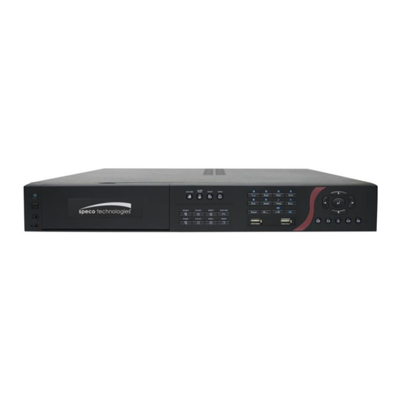
Hardware Introduction 1.2.1 Front Panel Name Function Power indicator: System power status indicators. Indicate running state of system. Lights when the system is running. (1) System indicator Recording indicator: When DVR system is recording, the light will keep flashing. (2) IR Sensor port For extended IR sensor cable(optional) (3) IR Sensor Receive signal from the remote control to operate the DVR unit... - Page 9 Name Function A functional key for multiple system control. Press to enable multiple function modes and the button will light up blue. To exit multiple function modes, press again. : Switch to single screen display mode : Switch to QUAD display mode : Switch to 9 spilt screen display mode (10) Number buttons : Switch to 16 split screen display mode...
-
Page 10: To Set A Video Segment And Save
Name Function Adjust the PTZ lens to the position that user wants. And then, press with (19) number button to setup the PTZ camera preset position. To speed up movement of PTZ camera lens (20) Speed + / Speed - To speed down movement of PTZ camera lens To focus in PTZ camera lens (21) Focus + / Focus -... -
Page 11: Back Panel
1.2.2 Back Panel Name Function (1) Video Loop Out(16CH) Output the video signal to a CCTV monitor. The Loop through cable is an optional accessory. (2) Video In Input the video camera signal and display it on channel 1~ 16. (3) Audio In &... -
Page 12: Chapter 2 Hardware Installation
Chapter 2 Hardware Installation Connecting Device 2.1.1 RS485 Cable Definition The following list is cable definition of the RS485 cable. RS485 cable figure RS485 cable site PTZ camera site (Color of cable) Green White Black The back panel of the DVR unit, user can connect up to 16 cameras of analog camera. The DVR unit also can connect 16 sensor devices, 4 alarm devices, and output video to 2 CRT/LCD monitor. - Page 13 For backup recorded video, plugging the flash drive or external hard disk through USB port, and then, use the bundled software enables user to playback and export video clip.
-
Page 14: Pin Definition Of Sensor/Relay/Rs485 Port
Pin Definition of Sensor/Relay/RS485 Port 2.2.1 Pin definition of Sensor and Relay The I/O card enables you to connect 16 sensor inputs and 4 relay outputs. Just connect the external sensor and relay pin directly to the I/O card pinhole. Check the table below and locate which pinhole is assigned to sensor input and relay output. -
Page 15: Pin Definition Of Rs485 Port
2.2.2 Pin Definition of RS485 Port The following is a pin definition of RS485 port on DVR server. Pin # Definition... -
Page 16: Using The Dvr Software
Chapter 3 Using the DVR Software Running the Unit for the First Time When the unit is turned on for the first time, the system will prompt you to enter the CD-Key that is located rear side of the DVR unit. If user wants to power off the DVR system, click Shutdown button. To restart the DVR system, click Reboot button. - Page 17 Name Function - About: Display current DVR program version. User also can update the DVR program (1) Exit firmware. Click the Update button and locate the firmware file to update. - Compact: Switch to compact mode - Guest: Switch to the guest mode. In guest mode, the functions are limited to preview and playback function only.
- Page 18 Name Function 4.2.4). Click “+” of group to (11) Camera Group To view the user defined channel group tree (see also Chapter extend group and drag the camera to surveillance screen to view. Click “+” of camera to Tree view the camera information. Click a desired icon to play the desired channel.
- Page 19 Name Function Click it to pop-up the Event Log Viewer dialog to check Event, Operation, POS (Point of (15) Event log Sales), System and Network logs. You can select a desired date and a log item to show all logs data in the table. (16) Sequence Start/Stop video screen cycle switch Use the entire area of the screen to only display the video.
-
Page 20: Using Event Log Viewer
3.2.1 Using Event Log Viewer Show the record of activities that take place in the system. 1. Click the Event Log button on DVR system main interface. The Event log viewer window will show up. 2. Select the Date to view or search certain event log by key word. Enter the key word in Find Text column and click Search button. -
Page 21: Using Posviewer
3.2.1.1 Using POSViewer Name Function (1) POSDB Path The storage path for POS event log. Click to change the storage path. (2) Before/After Set a time period before and after of POS event log. (3) Channel Select the POS event log of channel Enter specific key word or word string to search the POS event log. -
Page 22: Using Counting Log Viewer
3.2.1.2 Using Counting Log Viewer Click Counting Log Viewer button on Event Log Viewer window to search and view the list and statistic report of object counting. If the object counting function is not enabling, there will be no any data to view. To setup object counting, please refer to Chapter 4.2.1. -
Page 23: Using The Object Viewer
3.2.1.3 Using the Object Viewer Click Object Log Viewer button on Event Log Viewer window to view and search FaceFinder log. If the FaceFinder function is not enabling, there will be no any data to search and view. To setup FaceFinder, please refer to Chapter 4.2.2. -
Page 24: Familiarizing The Buttons In Playback Mode
Familiarizing the Buttons in Playback Mode To switch in Playback mode, click Playback button at the lower right corner of Preview mode user interface Name Function (1) Split Screen Mode Select from 6 kinds of split screen type to playback the recorded video file of all the camera, or one camera over the other or alongside on a single screen. - Page 25 Name Function (4) Playback Control Play: Play the recorded video file. Buttons Faster: Play the recorded video file at the speed of 2x, 4x, 8x,16x or 32x. Next: Go to the next frame. End: Go to the end of the recorded video file. Select the date on the calendar and the time from 00 to 23 to where to start playing the (5) Archive recorded video file.
- Page 26 Name Function (10)iPOS Serach To find iPOS event by keyword or period. POSDB Path: where the iPOS data located. Start Time: select the search start time and date End Time: select the search end time and date Select Camera: select the camera for iPOS events search Keyword: enter a keyword to search iPOS event Match whole words exactly: the iPOS event must 100% match the keyword that user has entered.
- Page 27 Name Function Use the entire area of the screen to only display the video. To return, press the right (13) Full screen button of the mouse or ESC on the keyboard or click the arrow icon on the screen. Click to exit from full screen mode When you switch to full screen in multiple-screen mode, Left click to toggle to only display one of the video in the multiple-screen mode or all.
-
Page 28: To Cut And Save The Wanted Portion Of The Recorded Video
3.3.1 To Cut and Save the Wanted Portion of the Recorded Video Use the Playback Control buttons or drag the bar on the playback progress bar and pause on where you want to start the cut. Then, click Segment button ( ) to set the begin mark. -
Page 29: To Bookmark A Section Of The Video
3.3.2 To Bookmark a Section of the Video Click Bookmark. The video playback stops when the bookmark button is executed. In the Bookmark dialog box, you may do the following: Add: To include the new reference mark in the bookmark list. In Bookmark Editor window, user can assign a name for this mark. -
Page 30: To Search Using The Visual Search
3.3.3 To Search Using the Visual Search Click Visual Search. In the Visual Search Setting dialog box, select the Camera number and the date. Then click OK. When a series of frames appear by date, click on the frame to display another series of frames and search by every Hour of that date, every Minute of that hour, every 10 Seconds of that minute, every Second of that 10 seconds. -
Page 31: To Search Using The Event Search
3.3.4 To Search Using the Event Search Click on the video screen on where you want to search. Click Event Search. The Event Search text (red) would appear at the lower left corner of the screen. In the Event Search Setting dialog box, check the type of condition you want to search. If you select POS, in the Find Text box, type the word. -
Page 32: To Search Using The Intelligent Search
3.3.5 To Search Using the Intelligent Search Click on the video screen on where you want to search. Click Intelligent Search. The Intelligent Search text (red) would appear at the lower left corner of the screen. When the Intelligent Search Setting dialog box and motion detector frame appear, you may adjust the sensitivity bar and the motion detector frame size and location. -
Page 33: Familiarizing The Buttons In Compact Mode
Familiarizing the Buttons in Compact Mode To view in Compact mode, click Exit button. In the logout dialog box, click Compact. Name Function (1) Split Screen Mode Select from 6 kinds of split screen type to view all the camera, or one camera over the other or alongside on a single screen. -
Page 34: Function Buttons In Ptz Camera Controller
Function Buttons in PTZ Camera Controller (11) (10) Name Function (1) Close Exit PTZ camera controller. (2) Setup Configure PTZ cameras (see Chapter 3.7). (3) AutoPan Operate the PTZ cameras automatically based on the selected camera group preset position number. (4) Focus +/- Adjust the focus manually to produce clear image. -
Page 35: Setting Up And Using The Emap
Setting Up and Using the EMAP EMAP can hold up to 8 maps in *.bmp/*.jpg format. You may locate the camera, sensor and relay on the map. 3.6.1 To Set Up the EMAP Click Emap. When the Emap screen appears, click the area number (1 to 8 buttons) on where you want to insert the map. -
Page 36: To Use The Emap
3.6.2 To Use the EMAP To use the EMAP: Click E-map. In the Emap screen, click the camera icon to switch on the area where the camera is located on the map and to display the video at the upper right corner of the Emap screen. At the lower right corner of the Emap screen, it lists all the warning message. -
Page 37: To Setup The Ptz/Ip Ptz Camera
To Setup the PTZ/IP PTZ Camera 3.7.1 Setup the PTZ Camera In the PTZ control panel, click Setup. When the PTZ Setup dialog box appears, select the camera number and check the Use PTZ box. Using this control panel to set the preset position In the Connection Settings section, select the COMPort where the PTZ camera is connected, PTZ ID number, BaudRate, and Protocol. - Page 38 15. When PTZ control icon has been click on, it will turn to red, the mouse cursor will become a red cross, and PTZ control bar will show up on the screen. - User can move the on screen PTZ controller to any position of screen - The on screen PTZ controller only display on a channel screen at a time.
-
Page 39: Setup The Ip Ptz Camera
3.7.2 Setup the IP PTZ Camera 1. In the PTZ control panel, click Setup. 2. When the PTZ Setup dialog box appears, click IP PTZ tab. 3. Select the camera number and check the Use PTZ box. 4. In the Connection Settings section, select the Protocol and Model of PTZ camera that user wants to connect and enter the IP or URL of IP camera in IP Camera Site column. - Page 40 16. When PTZ control icon has been click on, it will turn to red, the mouse course will become a red cross, and PTZ control bar will show up on the screen. - User can move the on screen PTZ controller to any position of screen - The on screen PTZ controller only display on a channel screen at a time.
-
Page 41: Customizing The Dvr System
Chapter 4 Customizing the DVR System In the Preview/Advanced screen mode, click button to customize your DVR. When the DVR configuration setup selection appears, select and click the buttons you want to change the setting. System Setting In the System Setting dialog box, click OK to accept the new settings, click Cancel to exit without saving, and click Default to revert back to original factory setting. - Page 42 In the Map Network Drive windows, select the Drive and fill in the network drive direction in Folder column if you know. Or click Browse to find the folder direction. Click Finish to complete the network drive mapping. After the network drive has been added, user needs to create a folder for network storage. In Browse For Folder windows, select the network drive and right click mouse button to add a new folder.
- Page 43 (3)Language Customize the system to display the system, interface, and tool tips based on the selected language. By default the language is in English. (4) Video Standard Change and select the proper video system according to your camera video system. If the video system setting is wrong, the video would appear abnormal.
- Page 44 - Status Report Send a daily system event and attention analysis report. To change the e-mail settings, click Setup. - Beep if no signal Make sound when the video signal is lost. - Mandatory Record Always record video when software is running. - Enable Overlay To enhance video signal for better video quality.
- Page 45 (13) System Configuration Display Setting Adjust resolution of display and adjust the touch monitor. Click Advance Setup to configure the monitor detail setting and the detail setting of monitor will be varied due to the brand of monitor that user has used. Adjust Touch Monitor: 1.
- Page 46 4. The partition can be named by clicking on Label column and enter the name. 5. To create more than one partition, do the steps 2 and 4 again. 6. When all the partition has been added, click Start to format all partitions. 7.
- Page 47 After connection successful, user should see the network drive on the Storage Path. To disconnect the mapping network drive, click Disconnect Network Drive. Ping IP: Allow user to ping and trace the certain IP address of network/server device on the network.
- Page 48 Others Printer Setting Click Add Printer and following the wizard to install a printer.
- Page 49 Regional/Language Setting When DVR application is using different language of UI besides English, user can select the corresponding region and language in order to make UI display correctly. Power Management To setup UPS configuration.
- Page 50 Device Management To manage the DVR system devices. Network Connection To manage the connection of the network. Phone and Modem options To setup the modem dial-up settings.
- Page 51 Date/Time Setup 1. Select the Month and Date. Click arrow button can switch to different month. 2. Select the Time Zone of DVR server located. 3. Adjust the Time by click spin box arrow button. 4. Click OK to save the configuration. Usageinfo To view usage of the system CPU, memory, and network.
- Page 52 Upgrade – To update the firmware of the System Controller. Model – Select model of the System Controller. If System Controller is connecting to DVR through the USB port, please select the System Controller Pro mode. If System Controller is connecting to DVR through the RS485 port, please select the System Controller Pro 485 model.
-
Page 53: To Set The Pos Setting
4.1.1 To Set the POS Setting 4.1.1.1 General Setting 1. In the System Setting dialog box, POS section, click Setting. 2. In the POS Console Setting dialog box, click Add to set a new POS setting, Modify to change the POS setting, and Delete to remove the selected POS setting. - Page 54 (5) Port Setting: Select the Local or Remote port to where it is connected. Local: Select the COM port number which is connected. Remote: Use the UDP protocol for remote connection if POS system can broadcast to Internet. Enter the IP address of the remote station. (6) Setup…: Set the COM Properties.
- Page 55 Setup POS Device There are some default POS devices. If user uses the POS device beside defaults, user can add new POS device and rules. The POS device can be added up to 50 include defaults. Setup Standard POS Device ...
- Page 56 - Include: set a rule for a lime with a string or character to be displayed. - Exclude: set a rule for a line with a string or character to be concealed. - Bill End: set a rule to divide each transaction. 4.
- Page 57 Setup XML POS Device XML can only work with the POS data is transmitting in XML format. Device: select or add a new device. Only device that supports XML can be configured in here. Click Add to add a device. Enter device name and select Type as XML. The POS device can be added up to 50 include defaults.
- Page 58 Please refer to the following example for more detail. <TicketStart> → Page Start <Header> → Root tag <MessageVersion>1.0</MessageVersion> <Date>20060317</Date> <Time>164216</Time> <RegisterID>3</RegisterID> → Sub tag <Shift>4</Shift> <CashierID>000000009</CashierID> <JrnlTransNum>3</JrnlTransNum> <JrnlID>0</JrnlID> </Header> </TicketStart> <Item> <SaleTotals> <Item> <SaleTotals> <Item> <SaleTotals> <TenderEvent> → Page End <TicketComplete>...
-
Page 59: Advanced Setting
4.1.1.2 Advanced Setting To setup POS text display position, text font and color. 1. In the System Setting dialog box, POS section, click Setting >> Advanced Setting 2. Mark Show POS Text to allow POS data to be display on surveillance screen. 3. -
Page 60: Pos Database Setting
4.1.1.3 POS Database Setting User can export the POS database to another save location or storage device. Click to change the save path. Mark Remove POS data after the POS data will be delete from DVR hard disk on the day that user has setup. -
Page 61: Camera Setting
Camera Setting In the Camera Setting dialog box, click OK to accept the new settings, click Cancel to exit without saving, and click Default1/ Default2 to revert back to original factory setting. (15) (13) (14) (10) (12) (11) (1) Camera Icons Select the camera number you want to adjust the video setting. - Page 62 (5) Input Select the type of video camera input you are using. - Analog Camera The video source is coming directly from camera that is connected to the SA Series DVR. - Remote DVR The video source is coming from another DVR server. In the Remote DVR dialog box, enter the server IP, port number, user ID, password and select the camera number.
- Page 63 In Camera Setting interface, click Detail to configure more parameters of the camera. Click OK to save the configuration and exit the setup windows. To reset the configuration back to factory value, click Default. User can select Video size, Frame rate, Video and Quality Mode of camera. And scroll the bar to adjust the Quality, Brightness, Contrast, Hue, Saturation, and Sharpness of the camera.
- Page 64 In the test section, click Test to check the sensor status. Red is high and Green is low. Click OK to exit and accept the setting and Cancel to exit without saving the setting. Relay Setting: To setup relay device that is embedded on the camera. 1.
- Page 65 Direct Link by IE Using IE browser to connect to camera and view the real time video. Click Direct Link by IE,the IE browser will pop up and connect to camera. The video viewing interface will be varied by different brand of camera.
-
Page 66: Setup The Object Counting
4.2.1 Setup the Object Counting The DVR system only supports 2 channels on object counting. 1. Click Detail to enter the object counting setup window. 2. Enable Detected Regions in Display section. This enables the object counting information show on the screen. - Page 67 8. Click OK to save the setting. Click Cancel to leave the setup window without saving. The object counting information will be display on the screen of upper part. Object Counting Information Display Region 1 Region 2 Object Size Frame...
-
Page 68: To Setup The Facefinder
4.2.2 To Setup the FaceFinder To setup the human face detection and capturing from live video for security issue. Click Detail to enter the FaceFinder setup window. To set the value back to default, click Default button. - The face detection angle is around 30 ~ 45 degrees for both side of face and 25 ~ 30 degrees for look up and down side of face. - Page 69 Select the time (second) and times (the number of face has been detected) from drag down list. - Reset Device Status After: Set the time period to reset activate device back to normal status. It works only when the activate status is set to trigger. After set up, click Start Test to test the configure result.
-
Page 70: Setup Ptz Tracking
4.2.3 Setup PTZ Tracking PTZ tracking allows user to setup a select range for PTZ camera to tracking the object automatically when object is out of selected rage. The PTZ tracking will be available when the camera is enabled PTZ function. 1. - Page 71 Minimum object size Maximum object size (6) Enable PTZ Auto Tracking: To restore PTZ tracking function after the camera has been manually control. The PTZ tracking will stop function when user has operated the PTZ camera manually. Therefore, user can enable this option to make sure the PTZ tracking will be restored after manually control of the PTZ camera.
-
Page 72: Create A Camera Group
4.2.4 Create a Camera Group Follow the below steps to create a camera group. The maximum of group number is 64. The default group can be deleted and modified. 1. Click to add a new group. 2. Right-click on group to rename the group name. 3. - Page 73 4. Right-click the camera can rename, delete, display/no display video of camera, and enable/disable camera. 5. To add another group, do the step 1 to 4 again. 6. To delete the group, click or right-click the group and select Delete. 7.
-
Page 74: Recording Setting
Recording Setting 4.3.1 Analog Camera In the Recording dialog box, click OK to accept the new settings, click Cancel to exit without saving, and click Default to revert back to original factory setting. (1) Camera Icons Select the camera number you want to set the recording setting. To select all the cameras, enable the ALL check box. - Page 75 When the system starts recording a red triangle mark would appear at the upper left corner of the screen. The recording modes are listed below: - Always Recording Record the video from the selected camera and save it to the designated storage path (see also Chapter 4.1 #1).
- Page 76 (5) Voice Detection Adjust the intensity of the audio detector. The system detects sound when it exceeds the intensity value. (6) Quality Adjust the video quality. The higher the value, the lower the compression level and uses more hard disk space.
- Page 77 User also can select the Default Mode High/Medium/Low. Click ? button to view default mode definition. (12) Group Click to view the camera group that user has been setup in Camera setup (see also Chapter 4.2.4). (13) Camera Click to view the camera live video on (14) Video Screen. (14) Video Screen Display the video of the selected camera.
-
Page 78: Ip Camera
4.3.2 IP Camera In the Recording dialog box, click OK to accept the new settings, click Cancel to exit without saving, and click Default to revert back to original factory setting. (1) Camera Icons Select the camera number you want to set the recording setting. To select all the cameras, enable the ALL check box. - Page 79 When the system starts recording a red triangle mark would appear at the upper left corner of the screen. The recording modes are listed below: - Always Recording Record the video from the selected camera and save it to the designated storage path (see also Chapter 4.1 #1).
-
Page 80: To Mask/Shield An Area On The Screen
(5) Group Click to view the camera group that user has been setup in Camera setup (see also Chapter 4.2.4). (6) Camera Click to view the camera live video on (7) Video Screen. (7) Video Screen Display the video of the selected camera. 4.3.3 To Mask/Shield an area on the screen In the Mask/Shield Edit section, activate the Enable Mask/Enable Shield check box. -
Page 81: Network Setting
Network Setting In the Network Setting dialog box, click OK to accept the new settings, click Cancel to exit without saving, and click Default to revert back to original factory setting. (1) Server Name Assign a name for the DVR unit. Letters of the alphabet and numbers only. (2) Transmitting Cameras Select and click on the camera number in the Transmitting Camera section you want to make it accessible via internet using WebViewer, Remote Console, PDAViewer and HandyViewer (still image). - Page 82 Enter the domain name here to check Click Query button to check domain name status The domain name has been found means the registration is successful. (5) Remote Control Server Enable/disable remote control from remote application (ex. CMPC). Enter the remote accessing port in Port column.
- Page 83 example, if user uses CMS version 7.3 and connect to DVR server with version 7.7, and then, user has to enable this option to make it work. It is due to that DVR system has new security protocol and it’s not compatible with old remote access software.
-
Page 84: Schedule Setting
Schedule Setting Schedule to record, backup, enable network, reboot and disable alarm of all the cameras either weekly or one time. The number from 00 to 23 represent the time in 24-hour clock. The left most column display the days in a week. To Set the Schedule Setting: Select the date in the calendar. - Page 85 Disable Alarm Deactivate the alarm at the set time temporarily. Turn on Relay # Active the relay at the set time. If there are no Relays are connected, Turn on Relay # function will not display in drag down list. The Relay number will depend on how many relays are connected. Specify to either schedule it weekly or one time.
-
Page 86: Backup Setting
Backup Setting In the Backup Setting dialog box, the number from 00 to 23 represent the time in 24-hour clock. The numbers from 01 to 16 represent the camera number. When you back up the file, you may find QPlayer application included in the backup folder (see also Chapter Select the date of the recorded file in the calendar you want to backup. -
Page 87: Setup Quick Backup
and divide the file sizes to facilitate burning into DVD or CD disc. If you do NOT want to keep the recorded file in the storage folder, enable Delete files after Backup check box. Click to set the path on where to store the backup file. Click to start archiving the selected file. -
Page 88: Sensor Setting
Sensor Setting The I/O device must be installed to use this function. Click the drop-down list and select the sensor ID number. Give a name to the sensor in Name column. Click External IO to configure external I/O device if it is available(see also Chapter 4.7.1) The system automatically detects the sensor and input relates information. -
Page 89: 4.7.1 To Setup External I/O Box
5. Click OK to save the setting. 6. To add more than one external I/O box, click Add and follow the above step 2~4. Speco 7. In External I/O box setup dialog, user will see all added External I/O. Click added External I/O box and click Add to scan the connected relays and sensors. -
Page 90: Relay Setting
9. All connected relays and sensors will be listed. User can click radio button to control relays’ status. And then, click OK to save the setting and click Cancel to exit and without saving. 10. All connected External I/O box and their modules will be listed as tree topology in External I/O Setup windows. -
Page 91: Alarm Setting
Alarm Setting In the Alarm Setting dialog box, click Add to insert and set new alarm setting, click Delete to remove the selected alarm setting, click OK to exit and save the setting, Cancel to exit without saving, and Default to revert back to original factory setting. - Page 92 period. In Video Loss, click the camera number to set the alarm condition when video is lost. Right click on the camera number to setup the Continuous trigger duration of Video Loss. Enter the time period for system to send out the alarm when video loss has continuous detected for a period. In Missing and Suspicious Object/Scene Change, click the camera number and select the certain object on the screen (right click on camera number for detailed setting), and when the certain object is missing or doubtful, the system will alarm.(see also...
- Page 93 System Reboot: when the DVR system reboot without abnormal condition, the system will send out the alarm message. Abnormal Reboot: when the DVR system reboot in irregular condition, the system will send out the alarm message. Recording is switched off: when the recording has been stopped, the system will send out the alarm message.
- Page 94 FaceFinder: Enable to send out the alarm when the selected channel has detected face. Only the camera has setup FaceFinder detection will be available for selecting. Enable/disable the POS Keyword check box, to scan the data from the POS if it matches the keyword (see also Chapter 4.9.10).
- Page 95 activated. Launch EMAP Display mini EMAP screen. TVOut1/TVOut2 Switch to only display the video on TV1/TV2 from where the alarm is activated. Select the camera from drop down list to specify which camera video to be displayed on TV when the alarm is triggered. ...
- Page 96 Relay Output Set to enable/disable the relay operation when the alarm is activated and to extend additional time in second before it stops the relay operation (see also Chapter 4.9.1). IP Camera Relay To trigger on/off IP camera relay. Play Warning Sound Play alarm sound.
-
Page 97: To Setup Alarm Relay
Camera #: the selected channel would be snapshot when an alarm is occurred. Video Size: select the size of snapshot picture. Number of picture: the number of picture that is going to be taken. Snapshot Interval: a time gap for next snapshot Save Path: a storage path for saving snapshot pictures. -
Page 98: To Setup The Alarm Sound Setting
4.9.2 To Setup the Alarm Sound Setting Next to the Play Warning Sound check box, click Detail. In the Alarm Sound Setting dialog box, click to select other wav file from other source or folder, Play to listen, Record to make a new copy of a sound. -
Page 99: To Setup Ftp Setting
(2) Mail To check if it is working, click Test Account button. From: Enter the sender e-mail address. To and CC: Enter the recipient email address and separate it with comma or a semicolon (;). Subject: Enter the message title. Message: Type the message. -
Page 100: To Setup Alarm Recording Setting
4.9.5 To Setup Alarm Recording Setting Next to the Start Recording check box, click Detail. In the Alarm Recording Setting dialog box, select the camera to enable/disable video recording. Enable All to select all cameras. In the Frame Rate selection, select As Setting to record the number of frames based on the Recording Setting or Max to record the maximum of frames based on the available speed. -
Page 101: To Setup Ptz Preset Point
In Local Phone Number text box, enter the GSM SIM card phone number. In Phone Num text box, enter the contact number. You may now set to send thru SMS &/or MMS. If you enable SMS setting, just enter the message in the text box. -
Page 102: To Setup Cmpc Setting
4.9.9 To Setup CMPC Setting Next to the Send to CMS check box, click Detail. In the CMS Setting, select the camera to enable/disable sending the video to CMS. Enable All to select all cameras. Then, click OK to accept the new settings and Cancel to exit without saving. -
Page 103: 4.9.11 Missing, Suspicious Object, And Scene Change Detected
4.9.11 Missing, Suspicious Object, and Scene Change Detected Missing Object Select the certain object on the screen for the system to detect; when the object is disappear or move and the system will alarm. Click OK to exit and save the configuration. To exam the setup condition, click Start Test. - Page 104 the object frame that user want to clean Scene Change When the camera has been moved, the system will alarm. 1. Select the camera number and press right button on the mouse to call up the setup windows. And then, click the Scene Change Tab. 2.
-
Page 105: 4.10 User Setting
4.10 User Setting Only users with Administrator privileges can access User Setting. In the User Setting dialog box, click Add to insert a new user, Delete to remove the selected user, Edit to modify the user control right, OK to exit and accept the setting, and Cancel to exit without saving the setting. - Page 106 - IP Camera Enable/disable user to add new IP camera when using the Web Viewer. - Remote Access Time Enable Infinite check box to access DVR without time limit. If you want to set time limit, enter the number of minutes in Minute text box. (4) Visible Camera Select the camera number that would allow the user to access or view.
-
Page 107: Chapter 5 Backup Video Players
Chapter 5 Backup Video Players You can playback the backup files using QPlayer applications. When you back up the recorded file, QPlayer applications are automatically included in the backup folder. With QPlayer, it is the same as in Playback mode and supports 6 different split screen types to view all the video at the same time. - Page 108 Name Function (6) Archive Select the date on the calendar and the time from 00 to 23 to where to start playing the recorded video file. – OPEN FILE: user can open the recorded file from HDD – Channel 01~ 16&Channel 17 ~ 32: Switch to different channel group of playback calendar.
- Page 109 Name Function (13) Event Log Show the record of activities that take place in the system. To filter the records, select and click the option button to only display Event, System, Operation, Network or POS. (14) Visual Search Search from a specific camera by Date, Hour, Minute, 10 Seconds and Second. (See also Chapter 3.3.3) (15) Find Next...
-
Page 110: Chapter 6 Using The Remote Programs
Chapter 6 Using the Remote Programs You can use Microsoft Internet Explorer to access DVR server by entering the IP address or domain name. To use this feature, make sure that you are connected to the internet and the Network feature is enabled. Accessing this feature for the first time you will be prompted by your browser to install WebCamX.cab, allow the installation and you should be able to connect and login afterwards. -
Page 111: Familiarizing The Webviewer Buttons
Familiarizing the WebViewer Buttons Right-clicking on the webcam video screen, enables you to Start Recoding, Video Quality, Select Camera, Enable DirectDraw, and view Server Information. Name Function (1) DirectDraw Enhance the video quality. Not all graphic cards can support this function. (2) Received file size Indicate the size of the data being sent per second. - Page 112 Name Function (14) Select cameras Select to the view camera from different server. In Select Camera dialog box, Display to view column, click to enable/disable viewing the camera. In Video Quality column, click to select between High, Normal or Low. Click Add Server and select the server type between DVR and IP Cam to add.
-
Page 113: To Setup Remote System Setting
6.1.1 To Setup Remote System Setting There are two type of remote setup mode – Basic Setting and Advance Setting. Select the setup mode and click OK to enter setup window. 6.1.1.1 Basic Setting Click OK to exit and save the setting and Cancel to exit without saving the setting. The setting here applies to Remote DVR only. - Page 114 (5) Auto Brightness Control Automatically adjust the brightness. (6) Night View Automatically adjust the exposure to make the image more visible especially when the site is dark. You can only use this function when the Auto Brightness Control is enabled. (7) Noise Reduction Reduce undesirable video signal and improve the quality of the video.
-
Page 115: Advance Setting
6.1.1.2 Advance Setting In WebViewer UI, click Remote Setup button ( ) to configure setting of the remote DVR server. After click Remote Setup button, the setup menu bar will appear as below shown: Click the setup selection to enter the setup window. To exit setup menu bar, click OK. System Setting In the System Setting windows, click Update to accept the new settings, click Cancel to exit without saving, and click Default to revert back to original factory setting. - Page 116 (6) Login Enable the conditions in Login section you want the system to automatically carry out. Auto record when login Automatically start video recording when the DVR is executed. Auto start Network when login Automatically connect to network when the DVR is executed. Login to Compact mode Switch to compact mode directly when the DVR is executed.
- Page 117 Right-Bottom. To change the POS data font and color, click Font. Mark Remove POS data after the POS data will be delete from DVR hard disk on the day that user has setup. iPOS Pro Setting Enable Multiple Windows for viewing multi-channels of iPOS live data. To save the iPOS live data window position on the preview mode, mark the Save Window Position.
- Page 118 Camera Setting Analog Camera Select the camera from remote DVR servers to modify settings. In the Camera Setting window, click Update to save and apply the new settings, click Cancel to exit without saving, and click Default1/ Default2 to revert back to original factory settings.
- Page 119 (8) Enable Deinterlace To enhance the video quality. Set the deinterlace mode to #1, if you are capturing motionless picture and select #2, if it captures lots of movement. IP Camera Select the camera from remote DVR servers to modify settings. In the Camera Setting window, click Update to save and apply the new settings, click Cancel to exit without saving, and click Default1/ Default2 to revert back to original factory settings.
- Page 120 Record Setting Analog Camera In the Recording setup window, click OK to accept the new settings, click Cancel to exit without saving, and click Default to revert back to original factory settings (1) Camera Icons Select the camera number you want to set the recording setting. To select all the cameras, enable the ALL check box.
- Page 121 rate setting in (6) Frame Rate section. - Voice Detecting Recording DVR system will record the sound when the voice exceeds the intensity value in Voice Detection setting. - No Recording The system won’t do any recording. KeyFrame Recording Only record one frame per second. (3) Motion Detection Adjust the sensitivity of the motion detector.
- Page 122 The blocks from 00 to 23 represent the time in 24-hour clock. To record in full 24 hours, select the recording mode and click the button. If you want to only record at a particular time, click the Schedule button and click colored block, then click on the time blocks in Recording Mode window.
- Page 123 (3) Dynamic DNS (Domain Name System) Enter the Domain Name and Password the user has setup when applied a DDNS. To use this feature, go to http://speco.dss.com.tw and register (see Appendix A). Use this service if the IP address changes each time when you connect to internet.
- Page 124 Enable new version DVR system to accept remote software with former version. For example, if user uses CMS version 7.5 and connect to DVR server with version 7.7, and then, user has to enable this option to make it work. It is due to that DVR system has some new security protocol in DVR with version 7.3 and newer version, and it’s not compatible with old remote software.
- Page 125 Schedule Setting Schedule to record, backup, enable network, reboot and disable alarm of all the cameras either weekly or one time. The number from 00 to 23 represent the time in 24-hour clock. The left most column display the days in a week. To Set the Schedule Setting: Select the date in the calendar.
- Page 126 Activate the relay at the set time. Number of relays are depending on the relays has connected with DVR system. Specify to either schedule it weekly or one time. Click to make a selection. Right click the colored blocks to set the schedule. In the Select time dialog box, click to enable or disable the portion user want to set.
- Page 127 Alarm Setting In the Alarm Setting window, click Add to insert and set new alarm setting, click Delete to remove the selected alarm setting, click OK to exit and save the setting, Cancel to exit without saving, and Default to revert back to original factory settings.
- Page 128 System Reboot: when the DVR system reboot without abnormal condition, the system will send out the alarm message. Abnormal Reboot: when the DVR system reboot in irregular condition, the system will send out the alarm message. Recording is switched off: when the recording has been stopped, the system will send out the alarm message.
- Page 129 6. In (5) Alarm Reset, click the camera number (use and to select the alarm) to set the reset condition of alarm. Once alarm is reset, all alarm action will stop at the moment. If the sensor normal status is high, set the sensor condition to low.
- Page 130 Setup FTP). - Start Recording Record the video from the selected camera. To setup click Detail (see also To Setup Alarm Recording). - Alarm SOP (Standard Operation Procedure) List the instructions to inform the person of what to do when the alarm is activated. To setup click Detail (see also To Setup Alarm SOP).
- Page 131 To Setup FTP Setting Next to the File Transmission via FTP check box, click Detail. In the FTP Setting dialog box, enter the FTP IP, port, user ID and password. In Number of Pic text box, enter the number of sequence images that want to send when file is transmitting.
-
Page 132: Familiarizing The Webviewer Ptz Buttons
Familiarizing the WebViewer PTZ Buttons Name Function (1) Direction buttons Adjust and position the focal point of the PTZ camera. Click the center to pan automatically. (2) Zoom +/- Zoom in and out the image. (3) Select PTZ Choose to enable/disable the PTZ camera. In the Select PTZ dialog box, Select column, click to enable/disable viewing and controlling the PTZ camera. -
Page 133: Familiarizing The Buttons In Remote Console
Familiarizing the Buttons in Remote Console Name Function (1) DirectDraw Enhance the video quality. Not all graphic cards can support this function. (2) Exit Close the Remote Console. (3) Volume Enable/disable the sound. (4) Split Screen Select from 6 different split screen type to playback the recorded video file of all the Mode camera, or one camera over the other or alongside on a single screen. -
Page 134: To Setup Remote Console Setting
Name Function (18) Alarm Alert and display warning info. Only Administrator-level can reset and turn on, off and trigger the Sensor and Relay by right-clicking the item in the Sensor and Relay list. 6.3.1 To Setup Remote Console Setting Click OK to exit and save the setting and Cancel to exit without saving the setting. (1) Storage Path Set the directory on where to save the data. -
Page 135: Familiarizing The Buttons In Ptz Camera Controller
6.3.2 Familiarizing the Buttons in PTZ Camera Controller (10) Name Function (1) Close Exit PTZ camera controller. (2) Setup Select the PTZ camera channel. (3) AutoPan Operate the PTZ cameras automatically based on the selected camera group preset position number. (4) Focus +/- Adjust the focus manually to produce clear image. -
Page 136: Using The Remote Playback
Using the Remote Playback To use this feature, first you need to select the source of the file. In the Select Playback Mode dialog box, choose Local Playback to open the file that is recorded in the Remote Console, and Remote Playback to open the file that is recorded in the DVR server. -
Page 137: Familiarizing The Buttons In Local Playback Mode
6.4.1 Familiarizing the Buttons in Local Playback Mode Name Function (1) Split Screen Mode Select from 6 different split screen types to playback the recorded video file of all the camera, or one camera over the other or alongside on a single screen. If there are only 4 cameras enabled, you won’t be able to switch to 9, 16, and 13 split screen mode. - Page 138 Name Function (6) Archive Select the date on the calendar and the time from 00 to 23 to where to start playing the recorded video file. – Also, user can open the recorded file from certain location by click OPEN FILE button –...
- Page 139 Name Function (18) Audio Enable/disable audio play (19) De-interlace To enhance the video quality. Set the de-interlace mode to #1, if you are capturing motionless picture and select #2, if it captures lots of movement.
-
Page 140: Familiarizing The Buttons In Realtime Playback Mode
6.4.2 Familiarizing the Buttons in RealTime Playback Mode Name Function (1) Split Screen Mode Select from 6 different split screen type to playback the recorded video file of all the camera, or one camera. To zoom in an area on the screen, Right click and Drag a square on the area you want to enlarge. (2) Exit Close the program Show the progress of the file being played. - Page 141 Name Function Select the date on the calendar and the time from 00 to 23 to where to start playing the (6) Archive recorded video file. – Also, user can open the recorded file from certain location by click OPEN FILE button –...
-
Page 142: Familiarizing The Buttons In Download And Playback Mode
6.4.3 Familiarizing the Buttons in Download and Playback Mode Name Function (1) Exit Close the program Show the progress of the file being played. You may move the bar to seek at any (2) Progress bar location of the track. (3) Playback Control From left to right: Buttons... - Page 143 Name Function (9) Visual Search Search from a specific camera by Date, Hour, Minute, 10 Seconds and Second. (See also Chapter 3.3.3) (10) Find Next Search for the next event or changes in the motion detector frame. You can use this when you are using Intelligent Search or Event Search function.
-
Page 144: Using Handyviewer To Access Dvr Server
Using HandyViewer to Access DVR server Users can use a mobile phone to access the DVR through Internet. Make sure your mobile phone support IE browser and is connected to the internet. To access the DVR server, open IE browser and enter http://enter server IP or domain name here/mobile. -
Page 145: To Install Pdaviewer From The Internet
6.6.2 To install PDAViewer from the Internet Make sure you are connected to the internet. Open the web browser and enter the server IP. Then c lick the hyperlink Download PDAViewer. When the Download dialog box appears, enable Open file after download and click Yes. -
Page 146: To Use The Pdaviewer
6.6.3 To Use the PDAViewer Run the PDAViewer in the Programs. Familiarizing the PDAViewer buttons. (10) Name Function Hook up to the DVR server. Make sure you are connected to internet. (1) Connect When the iView screen appears, click Add to add DVR server. Enter the server IP, port, user ID, password and select the connection type. - Page 147 Name Function (10) Direction buttons Adjust and position the focal point of the PTZ camera. To change the video quality, enable/disable audio, and select to display different camera, tap on the video screen longer the popup menu will appear. User also can view and change status of I/O devices On the preview screen, tap on video screen longer the popup menu will appear Select the Remote IO The sensor and relay devices will list as below:...
-
Page 148: To Playback In Pdaviewer
6.6.4 To Playback in PDAViewer 1. Run the PDAViewer in the Programs. 2. Hook up to the DVR server. 3. Click Connect icon and select the DVR server 4. Click Playback to enter playback option screen 5. Select the camera, data, and time 6. -
Page 149: To Use The Java-Viewer
6.6.6 To Use the Java-Viewer Run the Java-Viewer program. Enter the DVR IP address, port number, user ID, and password. Please refer to your DVR server setting for that information. And then, select the Connect to connect to DVR server. Click Yes to accept the data from DVR server. -
Page 150: Chapter 7 Ienhance
Chapter 7 iEnhance The bundled iEnhance is a video editing tool and can only be used with *.dvr video file. It allows you to adjust the video picture quality, segment and save the wanted portion of the video, zoom in and out the image, and print or save the screen shot. -
Page 151: To Use Istable
Name Function (17) Temporary Display the sample settings. Click the sample to apply the setting on the current video. Setting Block (18) Status Bar Display the date, and time of the video. (19) Progress Bar Show the progress of the file being played. You may move the bar to seek at any location of the track. - Page 152 10. To switch back to iEnhance interface, click iEnhance button...
-
Page 153: Chapter 8 Web Tools
Chapter 8 Web Tools The bundled Web Tools includes Dispatch Server and Remote Backup program. To install Web Tools, place the CD into the CD-ROM drive then click Install Web Tool. Dispatch Server Dispatch is designed to reduce the network traffic of the DVR server. Instead of connecting directly to the DVR server, the client can connect to the computer that is connected to the DVR server using the Dispatch program. -
Page 154: Remote Setup
Remote Setup Remote Setup is a tool for configuring DVR server from remote site. To install Remote Setup application, insert the Installation CD into CD-ROM drive and click Install Web Tools. After installation, click start the Remote Setup application. 8.2.1 To Add DVR server User need to add a DVR server and make connection in order to setup remote DVR server. -
Page 155: To Setup Remote Dvr Server
8.2.2 To Setup Remote DVR Server Select the DVR server from listing and click Setup to configure remote DVR server. 8.2.2.1 System Setting In the System Setting windows, click Update to accept the new settings, click Cancel to exit without saving, and click Default to revert back to original factory setting. - Page 156 (7) Miscellaneous Enable the conditions in Miscellaneous section you want the system to perform. Beep if no signal Make sound when the video signal is lost. Mandatory Record Always record video when software is running Enable Overlay To enhance video signal for better video quality. Screen Saver Set a period time to enter screen saver mode when system idle.
- Page 157 iPOS Pro Setting Enable Multiple Windows for viewing multi-channels of iPOS live data. To save the iPOS live data window position on the preview mode, mark the Save Window Position. To select all channels, mark All check box.
-
Page 158: Camera Setting
8.2.2.2 Camera Setting Analog Camera Select the camera from remote DVR servers to modify settings. In the Camera Setting window, click Update to save and apply the new settings, click Cancel to exit without saving, and click Default1/ Default2 to revert back to original factory settings. - Page 159 To enhance the video quality. Set the deinterlace mode to #1, if you are capturing motionless picture and select #2, if it captures lots of movement. IP Camera Select the camera from remote DVR servers to modify settings. In the Camera Setting window, click Update to save and apply the new settings, click Cancel to exit without saving, and click Default1/ Default2 to revert back to original factory settings.
-
Page 160: Record Setting
8.2.2.3 Record Setting Analog Camera In the Recording setup window, click OK to accept the new settings, click Cancel to exit without saving, and click Default to revert back to original factory settings (1) Camera Icons Select the camera number you want to set the recording setting. To select all the cameras, enable the ALL check box. - Page 161 rate setting in (6) Frame Rate section. - Voice Detecting Recording DVR system will record the sound when the voice exceeds the intensity value in Voice Detection setting. - No Recording The system won’t do any recording. KeyFrame Recording Only record one frame per second. (3) Motion Detection Adjust the sensitivity of the motion detector.
- Page 162 The blocks from 00 to 23 represent the time in 24-hour clock. To record in full 24 hours, select the recording mode and click the button. If you want to only record at a particular time, click the Schedule button and click colored block, then click on the time blocks in Recording Mode window.
-
Page 163: Network Setting
(3) Dynamic DNS (Domain Name System) Enter the Domain Name and Password the user has setup when applied a DDNS. To use this feature, go to http://speco.dss.com.tw and register. (see also Appendix A). Use this service if the IP address changes each time when you connect to internet. - Page 164 Enable new version DVR system to accept remote software with former version. For example, if user uses CMS version 7.5 and connect to DVR server with version 7.7, and then, user has to enable this option to make it work. It is due to that DVR system has some new security protocol in DVR with version 7.3 and newer version, and it’s not compatible with old remote software.
-
Page 165: Schedule Setting
8.2.2.5 Schedule Setting Schedule to record, backup, enable network, reboot and disable alarm of all the cameras either weekly or one time. The number from 00 to 23 represent the time in 24-hour clock. The left most column display the days in a week. - Page 166 Activate the relay at the set time. Number of relays are depending on the relays has connected with DVR system. Specify to either schedule it weekly or one time. Click to make a selection. Right click the colored blocks to set the schedule. In the Select time dialog box, click to enable or disable the portion user want to set.
-
Page 167: Alarm Setting
8.2.2.6 Alarm Setting In the Alarm Setting window, click Add to insert and set new alarm setting, click Delete to remove the selected alarm setting, click OK to exit and save the setting, Cancel to exit without saving, and Default to revert back to original factory settings. - Page 168 System Reboot: when the DVR system reboot without abnormal condition, the system will send out the alarm message. Abnormal Reboot: when the DVR system reboot in irregular condition, the system will send out the alarm message. Recording is switched off: when the recording has been stopped, the system will send out the alarm message.
- Page 169 6. In (5) Alarm Reset, click the camera number (use and to select the alarm) to set the reset condition of alarm. Once alarm is reset, all alarm action will stop at the moment. If the sensor normal status is high, set the sensor condition to low.
- Page 170 Setup FTP). - Start Recording Record the video from the selected camera. To setup click Detail (see also To Setup Alarm Recording). - Alarm SOP (Standard Operation Procedure) List the instructions to inform the person of what to do when the alarm is activated. To setup click Detail (see also To Setup Alarm SOP).
- Page 171 To Setup FTP Setting Next to the File Transmission via FTP check box, click Detail. In the FTP Setting dialog box, enter the FTP IP, port, user ID and password. In Number of Pic text box, enter the number of sequence images that want to send when file is transmitting.
-
Page 172: Remote Backup
Remote Backup Remote Backup is purely for backing up the *.dvr file from the DVR sever. You can select between Auto Backup and Manual Backup. Auto Backup continuously archives one hour of the recorded data at a time, starting from the specified date. As for Manual Backup, it only archives the recorded data of selected date. To back up the data, you must have at least 2G hard disk space. - Page 173 - Click Add to set the storage path. - Click Delete to remove the selected storage path. - Click Schedule to select/unselect the time you want to backup. The red block turns white when it is unselected. - Enable/disable Disk Recycle check box, to automatically overwrite the oldest file when there is not enough free space to backup the file.
- Page 174 8. For manually backup, click file select button. 9. And then, select the date and time that user wants to backup. 10. In Remote Backup window, click Start button to backup.
- Page 175 11. If user wants to burn the back file into DVD disk, click Burn button and select the file to burn.
-
Page 176: Appendix A Registering Domain Names
User Login Browse the website speco.dss.com.tw with Microsoft IE to access the following dialog. First input CD-Key number that is located at back panel of the DVR server and select the product name. Then click OK to login or Reset to clear the previous input. -
Page 177: Appendix B Network Service Port
Appendix B Network Service Port The following table shows the ports that DVR server uses for certain network service. Port # Variable Remote Console (CM 3000) 5550 WebViewer 2-way audio 9999 Remote Control (CM3000) 5555 DVR POS 5150 DVR DDNS (Upload / Download) 53 / 1053... -
Page 178: Appendix C Setting Up Raid
Appendix C Setting Up RAID Please follow the below steps to setup the RAID. 1. Restart the DVR system and press Delete button to enter the BIOS setup screen. 2. Select the IDE Configuration and press Enter button. 3. In Configuration SATA#1 as, select RAID and press F10 to save and exit. - Page 179 4. When the below screen show up, press CTRL + I. 5. Select Create RAID Volume.
- Page 180 6. In Create RAID Volume Menu screen, select RAID Level that user wants to create. Using up and down button to change selection.
- Page 181 7. And then, select the Disks. Press Enter to the select disks screen. Using Space key to select the disk. The selected disk will have a green triangle mark. 8. After select the RAID level and disks press Enter key to create the RAID volume. Press Y to confirm the creation.
- Page 182 9. After RAID volume created, user should see the RAID volume information in DISK/VOLUME INFORMATION section. 10. The RAID volume needs to be formatted before using. Please refer to Disk Management (13) System Configuration Chapter 4.1.
- Page 183 To Delete the RAID Volume Enter BIOS setup > press Esc key > press CTRL + I Select Delete RAID Volume. Select the RAID volume if there is more than one RAID volume. Press Delete key and press Y to delete the RAID volume.
-
Page 184: Appendix D Using Recovery Cd To Recovery System
Appendix D Using Recovery CD to Recovery System 1. Insert the recovery CD into the DVD-ROM drive of DVR unit. 2. Restart DVR unit (power off and power on). 3. The DVR system will start the recovery action. 4. When Recovery Tool Kit window appears, click Recovery System. - Page 185 5. The System Recovery Wizard will show up, click Next to continue. 6. Select the recovery target. And then, click Next. 7. Click Yes to confirm the selection. If user wants to change the recovery target, click NO and select another recovery target.
- Page 186 recovery process, click Abort button.
- Page 187 9. When completed massage window show up, the recovery process is completed. Click Exit to leave the System Recovery Wizard window. 10. In Recovery Tool Kit window, click Exit to remove the recovery CD-ROM and reboot the DVR system.
-
Page 188: Appendix E Pin Definition Of Audio In Port
Appendix E Pin Definition of Audio In Port The following table lists the pin definition of audio in port. Pin # Definition Pin # Definition RCA(1) RCA(2) RCA(3) RCA(4) RCA(5) RCA(6) RCA(7) RCA(8) RCA(9) RCA(10) RCA(11) RCA(12) RCA(13) RCA(14) RCA(15) RCA(16) Pin # Definition...
Need help?
Do you have a question about the DVRPC16T2TB and is the answer not in the manual?
Questions and answers