
Subscribe to Our Youtube Channel
Related Manuals for Ariston TVM63X NA


Summary of Contents for Ariston TVM63X NA
-
Page 1: Service Information
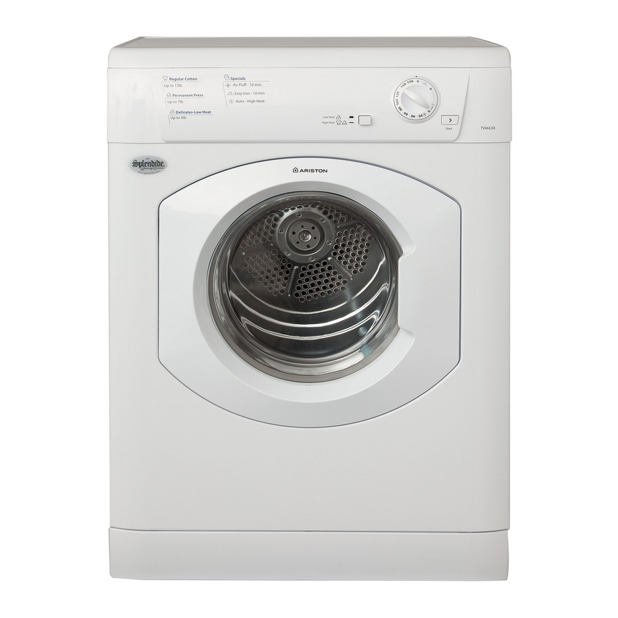
5407525 Issue 1 Jan 2010 ARISTON Electro- mechanical Vented Tumble Dryers Models Comm. Covered Code TVM63X NA 63076 Service Information Indesit Company UK Ltd © 2010 Reg. Office: Peterborough PE2 9JB Registered in London: 106725... -
Page 2: Safety & Servicing Notes & Serial Number Information
Indesit Company SAFETY NOTES & GENERAL SERVICING ADVICE 1. This manual is NOT intended as a comprehensive repair/maintenance guide to the appliance. 2. It should ONLY be used by suitably qualified persons having technical competence applicable product knowledge and suitable tools and test equipment. 3. -
Page 3: Table Of Contents
Indesit Company INDEX Safety & Servicing Notes & Serial Number Information ......2 Serial Number / Industrial Code Explanation ....... . . 2 Technical Specifications. -
Page 4: Technical Specifications
Indesit Company TECHNICAL INFORMATION Models Covered TVM63XNA 63076 White First Produced 2009 Electrical Rating 115 Volts AC 60Hz Power Consumption 1.45 kW 12 Amps Plug Type USA NEMA 5.15 Cable Length 1.8 Metres Features Reversing - Dual Heat - 170 minutes Programme Timer, Easy Iron (crease removal) and Auto Drying options. -
Page 5: Machine Function
Indesit Company MACHINE FUNCTION Cold air is drawn into the dryer cabinet interior through AIRFLOW DIAGRAM louvres in the cabinet base, passes through the large hole in the inner back panel adjacent to the fan and is driven through the element housing on the inner back panel. After passing through the element windings and through holes in the drum back plate into the drum interior, the now warm air is driven through the load to the front of the drum. -
Page 6: Console
Indesit Company Sequence of Automatic Drying System • First 20 minutes, full heat controlled by the timer. This is to pre-heat the clothes and drum before the exhaust thermostats take control. • The timer moves to its next cam position. The timer motor is now disconnected and the dryer tumbles and heats. -
Page 7: Programmes
Indesit Company PROGRAMMES Note: Program What it does... How to set it... Timed Drying 1. Select required heat setting HIGH Consult suggested drying Dries wet clothing that will be up to 170 minutes HEAT or LOW HEAT by pressing times ( see Laundry). ironed, acrylic fibers or small the HEAT button. -
Page 8: Component Description
Indesit Company COMPONENT DESCRIPTION CONSOLE PANEL This panel contains the user controls, which consist of a timer knob, for selecting the timed and sensed drying periods and a push switch for heat selection. TIMER The timer system is made up from two timers, one mounted on the console and one in the base of the machine. - Page 9 Indesit Company DOOR INTERLOCK Bitron Door Lock Operation door hook solenoid bistable cam latch Switch blade lever Door Open - Dryer Off Trying to turn the machine on with the door open, the solenoid is unable to operate the bistable cam to close the contacts, because it is locked by the latch.
- Page 10 Indesit Company HEATER ELEMENT The element comprises of front and rear pressings spaced apart with Mica type insulating material. Through the insulating pieces are 4 runs of coiled resistance wire supported from end to end by insulating material. High temperature insulated wires are crimped to the ends of the resistance strips to complete the circuit.
- Page 11 Indesit Company MOTOR A two pole P.S.C running at 2800 rpm with the impeller fitted to the rear end of the shaft and the drive belt running directly in grooves in the front end of the shaft. It is protected from overload by a self-resetting internal cut-out which interrupts the electrical supply to the windings.
-
Page 12: Timer Sequence Charts
Main Timer Sequence Chart 10 11 12 13 14 15 16 17 18 19 20 21 22 23 24 25 26 27 28 29 30 31 32 33 34 35 36 37 38 39 40 41 42 43 44 45 46 47 48 49 50 51 52 53 54 55 56 57 58 59 60 A u to C 3 - C 1 (C 3 - C 4) C 3 - C 2 (C 3 -C 5 ) -
Page 13: Wiring Diagram
WIRING DIAGRAM - TVM63X NA REAR VIEW OF CYCLING CONNECTOR FOR HEATER STAT = INSULATOR M = MALE TAB PB = PIGGY BACK PINK BROWN BLACK 160025148 BLUE ORANGE ORANGE 160025154 BLACK BROWN 160020201 160025152 ORANGE TIMER - EC Programme... -
Page 14: Dismantling Instructions
Indesit Company DISMANTLING INSTRUCTIONS SAFETY NOTES 1. Ensure that the machine is unplugged before commencing any work. 2. Beware of sharp edges on metal panels and pressed parts. Top Cover Remove the 2 screws securing the top cover to the back panel. Slide the top cover back and lift clear of the console. - Page 15 Indesit Company Side Panels Remove the top cover as in (A). Remove the plinth by pulling forward. Remove the screw behind the plinth. Remove the screw securing the side panel to the front panel. Remove the 4 screws securing the side panel to the rear panel. Pull the side panel backward to disengage from the lugs on the base panel.
- Page 16 Indesit Company Door Hinges The door must be removed and split as in (L1) - (6) above. Turn the door hinges inwards and slide the hinge upwards to disengage from the rear trim moulding as in Fig 1. Fig. 1 Front Bearings Remove the front panel as in (G).
- Page 17 Indesit Company Drive Belt Fitting Slide the new belt onto the drum and replace the front panel. Place the Special Tool, Part No. C00142716 (5600266), onto the inside edge of the new belt (cut out section of tool facing the drum). Ease the special tool onto the motor shaft as far as possible.
- Page 18 Indesit Company Rear Seal Remove the drum as in (Q). Remove the rear seal and clean any remnants of the seal and adhesive from the inner face of the inner back panel. Fit the new seal using adhesive Part No. C00981027 (981027). Motor Remove the right hand side panel as in (F).
- Page 19 Indesit Company Service Manual UK English 19 of 19...
Need help?
Do you have a question about the TVM63X NA and is the answer not in the manual?
Questions and answers
Dryer belt removal and installation for ariston dryer TVM63X
To remove and install the dryer belt for the Ariston dryer TVM63X:
Removal:
1. Remove the right-hand side panel.
2. Insert Special Tool Part No. C00142716 into the slot in the base of the dryer.
3. Hook the tool pegs into the belt and press down to release the belt from the motor shaft.
4. Release the top fixings of the front panel and pull it slightly away from the drum.
5. Slide the belt off the drum and remove it through the gap between the drum and front panel.
Installation:
1. Slide the new belt onto the drum and refit the front panel.
2. Place the Special Tool (cut-out section facing the drum) onto the inside edge of the belt.
3. Use the tool to stretch and fit the belt onto the motor shaft.
This answer is automatically generated