
Related Manuals for Gigabyte GH-PDU21-MF


Summary of Contents for Gigabyte GH-PDU21-MF
- Page 1 Intel Pentium 4 LGA775 / mPGA478 ® ® AMD AM2(940) / K8(939/754) Installation Guide GH-PDU21-MF REV.1003 051227...
-
Page 2: Table Of Contents
Power Installation and 3.5” Fan Speed Controller Installation........7 Power Installation and PCI Fan Speed Controller Installation........8 Installation Instructions for P4 LGA775RM & Cooler...........9 Installation Instructions for Intel® Pentium® 4 mPGA478 Clips........10 Installation Instructions for AMD AM2 (940) / K8 (939 / 754) Clip.........11 - 2 - GH-PDU21-MF... -
Page 3: Checklist
(4) AM2 / K8 clip (8) Speed control (12) Double-sided (9) Power cable (10) PCI bracket (11) GH-PDU21-MF & 3.5” bracket adhesive strip user's manual (note1) <note1> The double-sided adhesive strip is to attach the fan control box to the chassis. -
Page 4: Specification
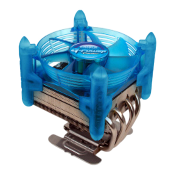
Unique fan frame design sustained by 4 artistic pillars Brilliant Blue LEDS Omni- directional cooler design Linear fan speed control module, suitable for both 3.5” front panel and PCI rear panel Easy clip installation – No tool required - 4 - GH-PDU21-MF... -
Page 5: Warranty Item
Products with a warranty sticker that is removed, torn or unreadable Due to the weight of the cooler exceeding normal standards, please remove the cooler before computer transport to prevent damage to the cooler itself as well as prevent problems during installtion. - 5 - GH-PDU21-MF... -
Page 6: Installation Instructions For Fan Control Box & Power Cable
Power connector for Cooler Connect the other end of the power Connect the other end of the power cable to the 3-pin CPU fan header cable to the 4-pin CPU fan header on the motherboard. on the motherboard. (LGA775) - 6 - GH-PDU21-MF... -
Page 7: Power Installation And 3.5" Fan Speed Controller Installation
Figure 4 Assure that one end of the power cable included with the GH-PDU21-MF cooler is connected to the fan control box (Figure 4-1). Connect the other end to the CPU fan header on the motherboard. Then the installation is completed . -
Page 8: Power Installation And Pci Fan Speed Controller Installation
PCI slot. Use screws to secure the PCI bracket in Figure 2-1 place. Figure 3 Repeat the steps in “Power Installation and 3.5” Fan Speed Controller Installation (Figure 2-1~Figure 4-2)”. Figure 3-1 The installation is now completed. - 8 - GH-PDU21-MF... -
Page 9: Installation Instructions For P4 Lga775Rm & Cooler
(Figure3-1).Repeat the steps in “Power Installation and 3.5” Fan Speed Controller Installation (Figure 2-1~Figure 4-2)”. The installation is now completed. GH-PDU21-MF provides manual fan speed control function. The fourth pin of the 4-pin CPU fan header does not necessarily have to be connected (Figure 3-2). -
Page 10: Installation Instructions For Intel® Pentium® 4 Mpga478 Clips
Figure 3-1 Figure 3-2 Figure 4 Repeat the steps in “Power Installation and 3.5” Fan Speed Controller Installation (Figure 2-1~Figure 4-2)”. The installation is now completed. Figure 4 - 10 - GH-PDU21-MF... -
Page 11: Installation Instructions For Amd Am2 (940) / K8 (939 / 754) Clip
CPU to secure the cooler atop the CPU. Repeat the steps in “Power Installation and 3.5” Fan Speed Controller Installation (Figure 2-1~Figure 4-2)”. The installation is now completed. Figure 4-1 Figure 4-2 - 11 - GH-PDU21-MF... - Page 12 - 12 - GH-PDU21-MF...
- Page 13 Intel Pentium 4 LGA775 / mPGA478 ® ® AMD AM2(940) /K8 (939 / 754) GH-PDU21-MF...
- Page 14 .......................15 .......................16 .......................16 .......................17 .......................17 ..............18 ...........19 ..............20 P4 LGA775 ...............21 Intel Pentium 4 mPGA478 ............22 ® ® AMD AM2(940) / K8 (939 / 754) ...........23 - 14 - GH-PDU21-MF...
- Page 15 (1) GH-PDU21-MF (3) P4 (2) LGA775 (4) AM2 / K8 (8) 3.5 (10)PCI (11) GH-PDU21-MF (12) - 15 - GH-PDU21-MF...
- Page 16 4 LGA775 840 / 670 / 570(3.8GHz) ® ® Intel ® Pentium ® 4 478 3.4GHz AMD AM2 (940) / AMD Athlon FX55 / AMD Athlon : Aluminum XP 4000+ P4 LGA775 P4 mPGA478 AMD AM2(940) / K8(939 / 754) (1,700~3,200 rpm) - 16 - GH-PDU21-MF...
- Page 17 B I O S - 17 - GH-PDU21-MF...
- Page 18 3 pin CPU fan 4 pin CPU fan (LGA775) - 18 - GH-PDU21-MF...
- Page 19 3 . 5 3 . 5 1-2) 3 . 5 2-1) 3-1) GH-PDU21-MF CPU fan 4-1) 4-2) - 19 - GH-PDU21-MF...
-
Page 20: Pci
3 . 5 1-1) 1-2) P C I 2-1) 2-1~ 4-2) - 20 - GH-PDU21-MF... -
Page 21: P4 Lga775
P4 LGA775 GH-PDU21-MF LGA775 LGA775 & P4 LGA775 LGA775 LGA775 LGA775 LGA775 3-1) 2-1~ 4-2) GH-PDU21-MF Intel ® Pentium ® mPGA478 - 21 - GH-PDU21-MF... -
Page 22: Intel ® Pentium ® 4 Mpga478
Intel ® Pentium ® 4 mPGA478 1-1) 1-2) 2-1~ 4-2) - 22 - GH-PDU21-MF... -
Page 23: Amd Am2(940) / K8 (939 / 754)
AMD AM2 (940) / K8 (939 / 754) C P U 1-2) C P U C P U 3 . 5 2-1~ 4-2) - 23 - GH-PDU21-MF... - Page 24 - 24 - GH-PDU21-MF...
Need help?
Do you have a question about the GH-PDU21-MF and is the answer not in the manual?
Questions and answers