Table of Contents
Advertisement
INSTRUCTIONS-PARTS LIST
This manual contains important
warnings and information.
READ AND KEEP FOR REFERENCE.
INSTRUCTIONS
LOW PRESSURE, MEDIUM VOLUME
HIGH-FLO Pumps
NOTE: Stainless steel pumps are severe-duty and electropolished,
for use with water-base coatings
Refer to page 2 for the Table of Contents.
For Pump Model Nos., Ratios and Working Pressures,
refer to page 3.
NOTE: Refer to manual 307–837 for adapter kits for mounting
the displacement pump to an existing motor.
Patent Pending
GRACO INC. P.O. BOX 1441 MINNEAPOLIS, MN 55440–1441
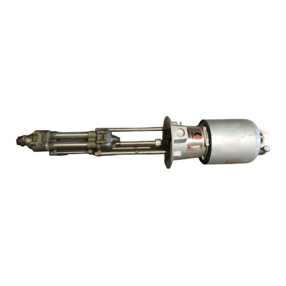
Model 220–569
Shown
COPYRIGHT 1987, GRACO INC.
Graco Inc. is registered to I.S. EN ISO 9001
307–809
Supersedes N
First choice when
quality counts.
(includes Rev. S
Rev. T
and PCN R
changes)
01921
Advertisement
Table of Contents

Related Manuals for Graco HIGH-FLO 220-569


Summary of Contents for Graco HIGH-FLO 220-569
- Page 1 Patent Pending GRACO INC. P.O. BOX 1441 MINNEAPOLIS, MN 55440–1441 Model 220–569 Shown COPYRIGHT 1987, GRACO INC. Graco Inc. is registered to I.S. EN ISO 9001 307–809 Rev. T Supersedes N First choice when and PCN R quality counts.
-
Page 2: Table Of Contents
Viscount Pumps Warranty Graco Phone Number ........... -
Page 3: Pump Models
NOTE: These pumps are not suitable for metering. Contact your Graco distributor for more information. Model No. Series Ratio and Type (parts list pages) 220–559 1.5:1 President (24) 220–560 2:1 President (24) 220–561 3:1 President (24) 237–223 3:1 President, w/PTFE packings (24) 220–574... -
Page 4: Warning Symbol
This equipment is for professional use only. Read all instruction manuals, tags, and labels before operating the equipment. Use the equipment only for its intended purpose. If you are uncertain about usage, call your Graco distributor. Do not alter or modify this equipment. Use only genuine Graco parts and accessories. - Page 5 FIRE AND EXPLOSION HAZARD Improper grounding, poor ventilation, open flames or sparks can cause a hazardous condition and re- sult in a fire or explosion and serious injury. Ground the equipment and the object being sprayed. Refer to Grounding on page 7. If there is any static sparking or you feel an electric shock while using this equipment, stop spray- ing/dispensing immediately.
- Page 6 Notes...
-
Page 7: Typical Installation
Proper sizing of the pump, accessories and lines is essential to get the maximum performance from your system. Contact your Graco distributor for assistance in designing a system to meet your needs. Mount the Pump This pump can be mounted on a floor stand, cart, wall bracket, or drum. -
Page 8: Air-Powered Pumps
Installation (Air-Powered Pumps) Air Line to Motor WARNING A bleed-type master air valve (D) is required in your system, to help reduce the risk of serious injury including splashing fluid in the eyes or on the skin, and injury from moving parts if you are adjust- ing or repairing the pump. - Page 9 Installation (Air-Powered Pumps) Fig. 2 Mix Tank Pump Stand Fluid Supply Line; 38 mm (1–1/2 in.) minimum diameter Fluid Shutoff Valve Fluid Line; 25 mm (1 in.) minimum diameter Surge Tank Stand G Surge Tank Ground Wire (required; see page 7 for installation) Air Supply Line Airline Filter Air Regulator and Gauge...
-
Page 10: Hydraulic-Powered Pumps
Installation (Hydraulic-Powered Pumps) Hydraulic Power Supply CAUTION The Hydraulic Power Supply must be kept clean at all times to avoid damage to the motor and hydraulic power supply. 1. Blow out hydraulic lines with air and flush thor- oughly before connection to the motor. 2. - Page 11 Installation (Hydraulic-Powered Pumps) Mix Tank Fluid Line; 25 mm (1 in.) Pump Stand minimum diameter Fluid Supply Line; Surge Tank Stand 38 mm (1–1/2 in.) G Surge Tank minimum diameter Ground Wire (required; see Fluid Shutoff Valve page 7 for installation) Fig.
-
Page 12: Operation All Pumps
Operation (All Pumps) Before You Start the Pump Read and follow all instruction manuals, labels and tags supplied with this pump and with all the accesso- ries you add to the system, before operating the sys- tem. Flush the Pump Before First Use The pump was tested in lightweight oil. -
Page 13: Air-Powered Pumps
Operation (Air-Powered Pumps) Starting and Adjusting the Pump 1. Charge the surge tank, if you are using one. See the separate instruction manual, 307–707. 2. Open all shutoff valves (D). 3. Open the dispensing valve/spray gun at the last gun station and keep it open while starting the pump. -
Page 14: Hydraulic-Powered Pumps
Operation (Hydraulic-Powered Pumps) Starting and Adjusting the Pump 1. Charge the surge tank, if you are using one. See the separate instruction manual, 307–707. 2. Open all shutoff valves (D). 3. Turn on the hydraulic power supply. 4. Open the flow control valve (S) all the way. 5. -
Page 15: Maintenance
The operating conditions of your particular system determine how often maintenance is required. Estab- lish a good maintenance schedule during the first several weeks of operation by recording when and what kind of maintenance is needed, and then deter- mine a regular schedule for checking your system. Your maintenance schedule should include the follow- ing: Flushing... -
Page 16: Air Line Filter
Air Line Lubricator Keep properly filled for automatic air motor lubrication. Air Line Filter Drain and clean as necessary. Hydraulic Power Supply Check Carefully follow the hydraulic power supply manufac- turer’s recommendations on reservoir and filter clean- ing, and periodic changes of hydraulic fluid. Mix Tank Volume Don’t let the mix tank run dry. -
Page 17: Troubleshooting
WARNING To reduce the risk of serious injury whenever you are instructed to relieve pressure, always follow the Pressure Relief Procedure on page 12. PROBLEM Pump output low on both strokes. Pump output low on only one stroke. Pump operates erratically. Pump will not operate. -
Page 18: Disconnecting The Displacement Pump
Disconnecting the Displacement Pump NOTE: In stand or wall-mounted installations, you do not have to remove the entire pump from its mounting. WARNING To reduce the risk of serious injury whenever you are instructed to relieve pressure, always follow the Pressure Relief Procedure on page 12. - Page 19 Model 220–569 Senator Pump Shown Lubricate threads. Torque to 102–109 N m (75–80 ft-lb). Torque to 68–75 N m (50–55 ft-lb). Fig. 5 Model 220–564 President Pump Shown Lubricate threads. Torque to 102–109 N m (75–80 ft-lb). Torque to 68–75 N m (50–55 ft-lb).
-
Page 20: Cleaning And Inspecting Parts
Repair Kits A pump seal kit is available for each pump size. Throat packing kits are also available, one for UHMWPE/ leather pumps and one for PTFE pumps. The piston seals may also be converted to PTFE. Refer to page 36 for ordering. - Page 21 Model 220–555 Severe–Duty Electropolished Stainless Steel Pump Shown OUTLET Fig. 9 Service Lips of v-packings must face down. Vented seat. Non-vented seat. Models 237–220 and 237–221 use 5 PTFE v-packings, instead of 3 UHMWPE (20) and 2 leather (25). INLET 17 (Ref) 01930...
- Page 22 Reassembling the Displacement Pump NOTE: When thread sealant is specified, use low strength (blue) Loctite . 1. Place the two halves of the piston (16) around the packing (15*) and snap them together. See Fig. 2. Apply thread sealant to the piston rod (17) threads. Screw the rod through the piston and packings and into the special piston nut (12).
- Page 23 01932 Side View of Outlet Housing (22) Fig. 10 Service OUTLET INLET Lips of v-packings must face down. Vented seat. Non-vented seat. Tighten uniformly. Torque to 34–40 N m (25–30 ft-lb). Torque to 68–81 N m (50–60 ft-lb). Apply sealant to threads. Left side.
-
Page 24: President Pumps
Parts (President Pumps) CARBON STEEL PUMPS Model 220–559, Series A, 1.5:1 Ratio Model 220–560, Series A, 2:1 Ratio Model 220–561, Series A, 3:1 Ratio Model 237–223, Series A, 3:1 Ratio Part Description 205–038 MOTOR, President; see 306–982 183–033 ROD, tie; 13.625” (346 mm) between shoulders 100–103 PIN, cotter;... - Page 25 Parts (President Pumps) CARBON STEEL PUMPS Model 220–559, Series A, 1.5:1 Ratio Model 220–560, Series A, 2:1 Ratio Model 220–561, Series A, 3:1 Ratio Model 237–223, Series A, 3:1 Ratio SEVERE-DUTY, ELECTROPOLISHED STAINLESS STEEL PUMPS Model 220–562, Series A, 1.5:1 Ratio Model 220–563, Series A, 2:1 Ratio Model 220–564, Series A, 3:1 Ratio Model 239–819, Series A, 3:1 Ratio...
-
Page 26: Assembly Procedure
Parts (President Pumps) Model 220–574, Series B 3:1 Ratio Carbon Steel President Pump, with 55 gal. drum cover and agitator Part Description 220–561 PUMP, President See page 24 for parts 237–309 COVER, drum, 55 gal. (200 liter) See 308–466 for parts 222–698 AGITATOR See 306–840 for parts... - Page 27 Parts (President Pumps) Model 220–574, Series B 3:1 Ratio Carbon Steel President Pump, with 55 gal. drum cover and agitator Includes items 201–208 Model 220–575, Series B 3:1 Ratio Stainless Steel President Pump, with 55 gal. drum cover and agitator Includes items 201–208 Ref No.
-
Page 28: Quiet Senator Pumps
Parts (Quiet Senator Pumps) CARBON STEEL PUMPS Model 220–565, Series A, 3.5:1 Ratio Model 220–566, Series A, 5:1 Ratio Model 220–567, Series A, 2.5:1 Ratio Part Description 220–571 MOTOR, Quiet Senator See 307–592 for parts 183–033 ROD, tie; 13.625” (346 mm) between shoulders 100–103 PIN, cotter;... -
Page 29: Quiet Bulldog Pumps
Parts (Quiet Bulldog Pumps) CARBON STEEL PUMPS Model 220–577, Series A, 4:1 Ratio Part Description 215–255 MOTOR, Quiet Bulldog See 307–304 for parts 183–033 ROD, tie; 13.625” (346 mm) between shoulders 100–103 PIN, cotter; 1/8” dia x 1–1/2” 108–284 PACKING, o-ring; buna-N 183–041 COUPLING 183–042... - Page 30 Notes...
-
Page 31: Viscount Pumps
Parts (Viscount I+ Pumps) CARBON STEEL PUMPS Model 236–601, Series A Model 236–605, Series A Model 236–712, Series A Part Description 236–417 MOTOR, hydraulic, Viscount I+ See 308–330 for parts 183–033 ROD, tie; 13.625” (346 mm) between shoulders 100–103 PIN, cotter; 1/8” dia x 1–1/2” 156–082 PACKING, o-ring;... -
Page 32: Carbon Steel Displacement Pumps
CARBON STEEL DISPLACEMENT PUMPS Model 220–549, Series D For Pump Models 220–560, 220–565, and 236–605 Model 220–551, Series D For Pump Models 220–559, 220–567, 220–577, and 236–712 Model 220–547, Series D For Pump Models 220–561, 220–566, and 236–601 Model 237–221, Series A For Pump Model 237–223 Part Description... - Page 33 CARBON STEEL DISPLACEMENT PUMPS Model 220–549, Series D For Pump Models 220–560, 220–565, and 236–605 Model 220–551, Series D For Pump Models 220–559, 220–567, 220–577, and 236–712 Model 220–547, Series D For Pump Models 220–561, 220–566, and 236–601 Model 237–221, Series A For Pump Model 237–223 NOTE: See Service Section for important assembly procedures, torque notes, and sealants.
-
Page 34: Electropolished Stainless Steel Displacement Pumps
SEVERE-DUTY ELECTROPOLISHED STAINLESS STEEL DISPLACEMENT PUMPS Model 220–555, Series E; for Pump Models 220–563, 220–568, and 236–606 Model 220–557, Series E; for Pump Models 220–562, 220–570, 220–578, and 236–713 Model 239–816, Series A; for Pump Model 239–815 Model 220–553, Series E; for Pump Models 220–564, 220–569, and 236–602 Model 239–820, Series A;... - Page 35 SEVERE-DUTY ELECTROPOLISHED STAINLESS STEEL DISPLACEMENT PUMPS Model 220–555, Series E; for Pump Models 220–563, 220–568, and 236–606 Model 220–557, Series E; for Pump Models 220–562, 220–570, 220–578, and 236–713 Model 239–816, Series A; for Pump Model 239–815 Model 220–553, Series E; for Pump Models 220–564, 220–569, and 236–602 Model 239–820, Series A;...
-
Page 36: Repair Kits
NOTE: Refer to the parts lists on pages 32–35 and the Service section on pages 20–23 for further information. Pump Seal Kit 220–589 For Pump Models 220–566, 220–569, 220–561, 220–564, 239–819, 236–601, and 236–602. Part Description 108–526 Packing 181–877 Gasket 181–680 Packing;... -
Page 37: Mounting Hole Diagram
1” npt(f) 1–1/2 in. npt(f) Mounting Hole Diagram 247.7 (9.75 in.) Four 11.1 mm (0.437 in.) diameter holes on 10.5 in. Bolt Circle Dimensions Pump Model President President Model 239–819 President Senator CST 1260 mm Senator SST Bulldog CST Bulldog SST Model 239–815 Bulldog SST... -
Page 38: Accessories
Use Only Genuine Graco Parts and Accessories Grounding Wire and Clamp 237–569 7.6 m (25 ft) long Bleed-Type Master Air Valve 2.1 MPa, 21 bar (300 psi) Maximum Working Pressure Relieves air trapped in the air line between the pump air inlet and this valve when closed. - Page 39 Use Only Genuine Graco Parts and Accessories Mounting Stand Kit 218–742 For mounting the surge tank to the floor. Pump Floor Stand 220–581 For mounting medium volume High-Flo pumps in a suction feed system. Refer to the Medium Volume High-Flo Accessories Manual, 307–837.
-
Page 40: Technical Data And Performance Charts President Pumps
1.5:1 Ratio President Pumps, Models 220–559 and 220–562 Maximum Working Pressure ..1.9 MPa, 19 bar (270 psi) Air Operating Range 0.1–1.2 MPa, 1.4–12 bar (20–180 psi) Air Consumption ....See Performance Chart Continuous Duty Delivery . - Page 41 3:1 Ratio President Pumps, Models 220–561, 220–564, 237–222, 237–223, and 239–819 ..Maximum Working Pressure 3.4 MPa, 34 bar (500 psi) Air Operating Range 0.1–1.1 MPa, 1.4–11 bar (20–166 psi) Air Consumption ....See Performance Chart Continuous Duty Delivery .
-
Page 42: Senator Pumps
3.5:1 Ratio Quiet Senator Pumps, Models 220–565 and 220–568 Maximum Working Pressure 2.45 MPa, 24.5 bar (350 psi) Air Operating Range 0.28–0.7 MPa, 2.8–7 bar (40–100 psi) Air Consumption ....See Performance Chart Continuous Duty Delivery . - Page 43 5:1 Ratio Quiet Senator Pumps, Models 220–566 and 220–569 ..Maximum Working Pressure 3.4 MPa, 34 bar (500 psi) Air Operating Range 0.28–0.7 MPa, 2.8–7 bar (40–100 psi) Air Consumption ....See Performance Chart Continuous Duty Delivery .
- Page 44 Notes...
-
Page 45: Bulldog Pumps
4:1 Ratio Quiet Bulldog Pumps, Models 220–577, 220–578, and 239–815 ..Maximum Working Pressure 2.8 MPa, 28 bar (400 psi) Air Operating Range 0.28–0.7 MPa, 2.8–7 bar (40–100 psi) Air Consumption ....See Performance Chart Continuous Duty Delivery . -
Page 46: Viscount Pumps
Viscount I+ Pumps, Models 236–601 and 236–602 ..Maximum Working Pressure 3.1 MPa, 31 bar (450 psi) Maximum Hydraulic Working Pressure Continuous Duty Delivery ..36.5 liter/min (9.6 gpm) Pump Cycles Per Liter (gallon) . -
Page 47: Manual Change Summary
Viscount I+ Pumps, Models 236–712 and 236–713 Maximum Working Pressure 1.55 MPa, 15.5 bar (225 psi) Maximum Hydraulic Working Pressure Continuous Duty Delivery ... Pump Cycles Per Liter (gallon) ....Maximum Recommended Pump Speed Maximum Hydraulic Motor Fluid Temperature Hydraulic Fluid Inlet... -
Page 48: Warranty
Graco distributor to the original purchaser for use. With the exception of any special extended or limited warranty published by Graco, Graco will, for a period of twelve months from the date of sale, repair or replace any part of the equipment determined by Graco to be defective.
Need help?
Do you have a question about the HIGH-FLO 220-569 and is the answer not in the manual?
Questions and answers