Table of Contents
Advertisement
Advertisement
Table of Contents

Related Manuals for Ducati MH900 EVOLUZIONE


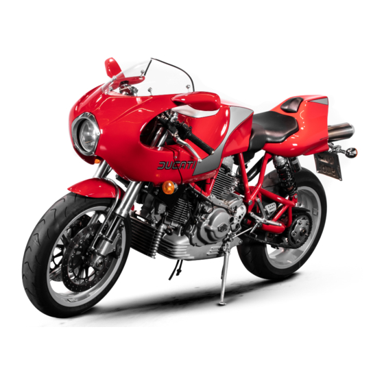
Summary of Contents for Ducati MH900 EVOLUZIONE
- Page 1 Owner’s manual DUCATIMH900evoluzione...
- Page 3 Ducati motorcycle for long manual. The information contained herein is valid at the journeys as well as short daily trips. Ducati Motor Holding time of going to print. Ducati Motor Holding S.p.A. S.p.A. wishes you smooth and enjoyable riding.
-
Page 4: Table Of Contents
TABLE OF CONTENTS Setting the rear brake pedal 18 Main components and devices 19 Location 19 Tank filler plug 20 Side stand 20 Shock absorber adjusters 21 Steering damper 22 General Warranty 6 Directions for use Symbols 6 Running-in recommendations 23 Useful information for safe riding 7 Pre-ride checks 24 Carrying the max load allowed 8... - Page 5 Charging the batteries 40 Checking the drive chain tension 41 Chain lubrication 41 Replacing bulbs 42 Beam setting 45 Tyres 46 Checking engine oil level 48 Cleaning and replacing the spark plugs 49 Cleaning the motorcycle Storing the bike away Important notes 50 Technical data Overall dimensions 51...
-
Page 6: General
Failure to comply with these instructions may put staff have access to the implements required to perform you at risk and lead to severe injury or death. any servicing job at best, and use Ducati original spare parts only as the best guarantee for full Important interchangeability, smooth running and long life. -
Page 7: Useful Information For Safe Riding
Useful information for safe riding Be very careful when tackling road junctions, or when riding in the areas near exits from private grounds, car Warning parks or on slip roads to access motorways. Read this section before riding your motorcycle. Always turn off the engine when refuelling. -
Page 8: Carrying The Max Load Allowed
Carrying the maximum load allowed Accessories Your motorcycle is designed for long-distance riding, The motorcycle is supplied with paddock stand and carrying the maximum load allowed in full safety. authenticity certificate. Even weight distribution is critical to preserving these safety features and avoiding trouble when performing sudden manoeuvres or riding on bumpy roads. -
Page 9: Identification Data
Identification data All Ducati motorcycles have two identification numbers, for frame (fig. 1.1) and engine (fig. 1.2). Frame number Engine number Note These numbers identify the motorcycle model and should always be indicated when ordering spare parts. Note fig. 1.1 To expose engine serial number, remove the oil sump guard on the left side. -
Page 10: Controls
CONTROLS Warning This section details the position and function of all the controls you need to drive your motorcycle. Be sure to read this information carefully before you use the controls. Position of motorcycle controls (fig. 2) 1) Instrument panel. 2) Key-operated ignition switch and steering lock. -
Page 11: Instrument Panel
4) Green light N. Comes on when gearbox is in neutral. 5) Yellow light Comes on when there are about 4 litres of fuel left in the DUCATI tank. 6) Green light Comes on and flashes when a turn indicator is on. -
Page 12: Digital Lcd Functions
Digital LCD functions will flash, whereas the wording USA will flash when current setting is mph. Check Press button 1 to toggle the EU and USA indications. When the ignition key is switched ON, the rev counter is Hold down button 2 for at least 5 seconds to store new set to zero, all figures on the LCD come on for 2 setting. -
Page 13: Keys
Keys (fig. 5) Ignition switch and steering lock (fig. 6) Your Ducati was delivered with two universal keys for It is located in front of the steering head and has four ignition and steering lock and a key identification plate positions: (1). -
Page 14: Left Switch
Left switch (fig. 7) 1) Switch, light switch, 3 positions: Down = light off; Centre = front and rear parking light, number plate light and panel lights on; = headlamp, front and rear parking lights, number plate light and panel lights on. 2) Light dip switch, two positions: position = low beam on;... -
Page 15: Clutch Lever
Clutch lever (fig. 8) Lever (1) disengages the clutch. It features a dial adjuster (2) for lever distance from the twistgrip on handlebar. To set lever distance from twistgrip, push lever (1) fully forward and turn the dial adjuster (2) to one of its four positions. -
Page 16: Right Switch
Right switch (fig. 9) Front brake lever (fig. 9) 1) ENGINE STOP switch, two positions: Pull in the lever (4) towards the twistgrip to operate the position (RUN) = run. front brake. The system is hydraulically operated and you position (OFF) = stop. -
Page 17: Rear Brake Pedal
Gear change pedal (fig. 11.1) Rear brake pedal (fig. 10) The gear change pedal is at rest when in the central Push down on the pedal (1) to apply the rear brake. position N, is moved up and down to change gears and The system is hydraulically operated. -
Page 18: Setting The Gear Change Pedal
Setting the gear change pedal (fig. 11.2) The gear change and rear brake pedals can be adjusted to suit the preferred riding position of each rider. To set the gear change pedal, lock linkage (1) and loosen the check nuts (2) and (3). Note Nut (2) has a left-hand thread. -
Page 19: Main Components And Devices
MAIN COMPONENTS AND DEVICES Location (fig. 12) 1) Tank filler plug. 2) Steering damper. 3) Side stand. 4) Rear view mirrors. 5) Rear shock absorber adjusters. 6) Exhaust silencer (see note on page 29). fig. 12... -
Page 20: Tank Filler Plug
Tank filler plug (fig. 13) Side stand (fig. 14) Opening Important Place the palm of your hand on the plug (1) and turn Before lowering the side stand, make sure that the anticlockwise. ground surface is hard and flat. Closing Do not park on soft or pebbled ground or on asphalt Turn the plug (1) clockwise with the palm of your hand melted by the sun heat and similar or the motorcycle... -
Page 21: Shock Absorber Adjusters
Shock absorber adjusters The shock absorber is equipped with outer adjusters that enable you to adjust your motorcycle to the load. The ring nut (1) located on the bottom connection holding the shock absorber to the swingarm, controls rebound damping. The knob (2) located over the shock absorber expansion reservoir (3) controls compression damping. -
Page 22: Steering Damper
STANDARD setting: Steering damper (fig. 16) - Ring nut (1) is turned all the way towards "hard". Rotate The steering damper is before the tank and is secured to towards "soft" and count 10 clicks. the frame and the steering head. - Knob (2) is turned all the way towards "hard". -
Page 23: Directions For Use
Furthermore, the drive chain should be inspected frequently. Lubricate it as required. DUCATI From 1000 to 2500 km At this point, you can squeeze some more power out of your engine, being careful, however, to never exceed 7000 rpm. -
Page 24: Pre-Ride Checks
Tyre condition Failure to comply with these rules will release Ducati Check tyre pressure and condition (page 46). Motor Holding S.p.A. from any liability whatsoever for Controls resulting engine damage or shorter engine life. Work the brake, clutch, throttle and gear change controls... -
Page 25: Starting The Engine
Starting the engine Note Follow the “High ambient temperature” procedure to start the engine when it is warm. Warning Before starting the engine, become familiar with the controls you will need to use when riding. Never start or run the engine indoors. Exhaust gases are poisonous and may lead to loss of consciousness or even death within a short time. - Page 26 Important Never operate the starter more than 5 seconds at a time. If needed, allow 10 seconds before attempting to restart the engine. 4) Move the fast-idle lever towards its vertical position (A, fig. 18.2) until the engine is running at approx. 1400-1500 rpm.
-
Page 27: Moving Off
Moving off Braking 1) Disengage the clutch squeezing the control lever. Slow down in time, shift down to engine-brake first and 2) Push down on gear change lever sharply with the tip then brake applying both brakes. Pull the clutch lever of your foot to engage the first gear. -
Page 28: Stopping The Motorcycle
Refuelling Stopping the motorcycle Slow down gradually, then shift down and release the Never overfill the tank when refuelling. Fuel should never throttle twistgrip. Finally change from first to neutral. be touching the filler (fig. 20). Apply brakes and you will bring the motorcycle to a complete stop. -
Page 29: Parking
Parking Stop the motorcycle, then put it on the side stand to park it (see page 20). To avoid theft, turn the handlebar fully left and turn the key to LOCK position. If you park in a garage or other facilities, make sure that there is proper ventilation and that the motorcycle is not near a source of heat or sparks. -
Page 30: Tool Kit And Accessories
Tool kit and accessories (fig. 22) The tail section behind the seat accommodates a compartment (1, fig. 22) that contains several objects. To access this compartment, pull out the small backrest (2, fig. 22). The compartment (1, fig. 22) holds: an Owner’s manual;... -
Page 31: Main Maintenance Operations
MAIN MAINTENANCE OPERATIONS Removing the seat The seat (1, fig. 24) is fixed to the tail fairing (2) (seat support) by two stud bolts (3, fig. 25). The fixing nuts can be accessed from underneath the tail fairing. To remove the seat support (2) (tail section), unscrew the fig. -
Page 32: Removing The Front Fairing
Removing the front fairing The front fairing is divided into two sections that can be taken apart: - body; - headlight fairing. Removing the body Disconnect the electric connector (1, fig. 27) (on both sides, under the body) for the front turn indicators. Unscrew the screws (2, fig. -
Page 33: Removing The Fuel Tank
Lift the headlight fairing (9, fig. 30) gently from the front Removing the fuel tank end. Note Before you can remove the fuel tank, you will need to remove the body (see page 32). Caution Do not smoke when performing these operations. Unscrew and remove the rubber spacers (1, fig. -
Page 34: Refitting The Fuel Tank
Refitting the fuel tank Place the tank in position. Install the rubber spacers (1, fig. 31) and tighten them. Fit the quick couplings for the delivery and return lines (2, fig. 32). Be sure to match the colours properly (connect white to white and black to black) and smear some lubricant on the O-rings. - Page 35 Warning If pressed accidentally, the pins (F, fig. 34) will closed cause the laminations of the quick couplings to close. Make sure the laminations are open. If not so, press the push to open tabs (A, fig. 33) to open them. Connect the fuel sensor (3, fig.
-
Page 36: Changing The Air Filter
Changing the air filter (fig. 36) The air box is accessible after removing the front body (see page 32) and the fuel tank (see page 33). Take off the air box cover (1, fig. 36) as follows: - unscrew the two front screws (2); - unscrew the rear screw (3);... -
Page 37: Checking Brake And Clutch Fluid Level
Brake system If you find exceeding play on brake lever or pedal and brake pads are still in good condition, contact your Ducati Dealer or an Authorised Workshop to have the braking system inspected and any air drained out of the circuit. -
Page 38: Checking Brake Pads For Wear
Ducati Dealer or Authorised Workshop. Rear brake... -
Page 39: Throttle Cable Adjustment
Throttle cable adjustment The throttle twistgrip must have a free play of 1.5-2 mm, measured at the edge of the twistgrip and at all positions of the handlebars. If it needs adjusting, use the suitable adjuster (2, fig. 40) provided on the throttle control. 2 - 4 mm ➤... -
Page 40: Charging The Batteries
Charging the batteries (fig. 41) Before charging the batteries, it is best to remove them from the motorcycle. Always disconnect the black negative terminal (-) first, and then the red positive terminal (+). Unscrew the two screws (1) that hold the battery brackets (A) to the battery mounts (B). -
Page 41: Checking The Drive Chain Tension
The lower portion of the chain should have a slack of 35-37 mm. If not so, contact a Ducati Dealer or an Authorised Workshop to have the chain tensioned up. Warning Tightening the rear wheel hub screws properly is 35 ÷... -
Page 42: Replacing Bulbs
Replacing bulbs Before replacing a burnt-out bulb, make sure that the new one complies with voltage and wattage as specified on page 58 - “Electric System”. Note You will need to remove the headlight fairing before you can access the headlamp. Headlamp To gain access to headlamp bulbs, slacken the retaining screws (1, fig. - Page 43 Refit the connector (5, fig. 45) matching it properly with the bulb pins. To remove the bulb (8, fig. 43), simply take out the bulb rubber holder (9, fig. 46) and pull the bulb out of its socket, then fit a new bulb with equal rating. Note Test the new bulb before reassembling the headlight.
- Page 44 Stop light (fig. 47) To replace the stop and parking light bulb, unscrew the two screws (3) that secure the glass (4). Remove the glass. The bulb is of the bayonet-type: press and rotate anti-clockwise to remove. Fit the spare bulb by pressing and turning clockwise until it clicks.
-
Page 45: Beam Setting
Beam setting (fig. 49) When checking for proper beam setting, put the motorcycle upright. Tyres should be inflated at the correct pressure and one person should be sitting astride the motorcycle, keeping it at right angles to its longitudinal axis and opposite a wall or a screen, 10 metres apart from it. -
Page 46: Tyres
0.2 - 0.3 bar. Important Do not remove or shift the wheel balancing weights. Note If tyres need replacing, contact a Ducati Dealer or Authorised Workshop to make sure wheels are removed and refitted correctly. - Page 47 Minimum tread depth Measure tread depth (S, fig. 51) at the point where tread is most worn down. It should not be less than 2 mm and anyway not below the legal limit. Important Visually inspect the tyres at regular intervals to detect cracks or cuts, on the side walls especially, bulges or large spots that are indicative of internal damage.
-
Page 48: Checking Engine Oil Level
Undo the filler plug (2) and top up to correct level. Refit the plug. Important Engine oil and oil filters must be changed by a Ducati Dealer or Authorised Workshop at regular fig. 52 intervals, as specified in the routine maintenance chart (see Warranty Booklet). -
Page 49: Cleaning And Replacing The Spark Plugs
If colour has altered or you find any dark deposits, change the spark plug and report this to a Ducati Dealer or Authorised Workshop. Check wear on the central electrode. If it looks worn out or has a vitreous appearance, change the spark plug. -
Page 50: Cleaning The Motorcycle
Ducati Spare Parts Department. This will Clean off stubborn dirt or exceeding grease from engine protect paintwork and let condensate breathe out. parts using a degreasing agent. Be sure to avoid contact with drive parts (chain, sprockets, etc.) -
Page 51: Technical Data
TECHNICAL DATA Weights Dry weight: 186 Kg. Carrying full load: 290 Kg. Warning Failure to observe weight limits could result in poor Overall dimensions (mm) (fig. 54) handling and impair the performance of your motorcycle, and you may lose control of the motorcycle. ➤... -
Page 52: Top-Ups
Top-ups Type of fluid cu. dm. (litres) Fuel tank, including a reserve 95-98 RON fuel of 3.5 cu dm (litres) Oil sump and oil filter SHELL Advance Ultra 4 Front/Rear brake and clutch circuits SHELL-Advance Brake DOT 4 – Protectant for electric contacts SHELL-Advance Contact Cleaner –... -
Page 53: Engine
Desmodromic timing system (fig. 55) Engine 1) Opening (or upper) rocker; Twin cylinder, four-stroke, 90° “L” type, longitudinal. 2) opening rocker shim; Bore mm: 3) split rings; 4) closing (or lower) rocker shim; Stroke mm: 5) return spring for lower rocker; 6) closing (or lower) rocker;... -
Page 54: Performance Data
RA 6 HC. Max. speed: 215 Kph. Important Brakes Failure to comply with these limits releases Ducati Motor Holding S.p.A. from any liability whatsoever for Front brake resulting engine damage or shorter engine life. Type: drilled steel twin-disc. Disc diameter: 320 mm. -
Page 55: Transmission
Braking surface: Transmission 25 sq cm Multi-plate dry clutch; Brake calliper: operated by a control lever on left handlebar. cylinder Ø 32 mm Drive is transmitted from engine to gearbox main shaft Make and type: via spur gears. BREMBO P 2.I05N. Ratio: Friction material: 32/59. -
Page 56: Frame
Steering angle (on each side): However, if you wish to tune up your motorcycle for 23° competitive trials, you may refer to Ducati Motor Holding Steering head angle: S.p.A. who will be glad to provide information about the 23.5°... -
Page 57: Tyres
Tyres The swingarm hinges on a pivot pin passing through the engine. Front tyre Tubeless, radial tyre. The whole system gives the bike excellent stability. Size: Travel: 120/65-VR17 or as an option 120/70 ZR17. 90 mm. Rear wheel travel: Rear tyre 130 mm. -
Page 58: Electric System
Electric system Fuses Basic electric items are: The main fuse box is located under the fuel tank (on RH Round headlamp with iodine double filament bulb, 12V- side). 55/60W bulb. To expose the fuses, take off the box protective cover (A, Parking light with 12V-5W bulb. - Page 59 IN GOOD CONDITION BLOWN fig. 59 fig. 57 fig. 58...
- Page 60 Legend of the wiring diagram of electric 30) Generator system/injection 31) Neutral light switch 1) Right switch 32) Oil pressure switch 2) Key-operated switch 33) Rear STOP light switch 3) Ignition relay 34) Front STOP light switch 4) Fuse box 35) Left switch 5) Flasher 36) Air temperature sensor...
- Page 61 Y Yellow Legend of fuse box (4) P Pink R-Y Red-Yellow Pos. Description Rtg. Y-G Yellow-Green G Green Main switch 30 A Bn-Bk Brown-Black W-R White-Red 2-10 High and low beams 15 A Bn-W Brown-White V-Bk Violet-Black 3-11 Turn indicators, warning lights, 7.5 A B-W Blue-White parking lights and instrument...
-
Page 62: For United States Of America Version Only
Such use could lead to upset or other accident. Noise emission warranty Ducati Motor S.p.A. warrants that this exhaust system, at Reporting of safety defects the time of sale, meets all applicable U.S. EPA Federal If you believe that your vehicle has a defect which could noise standards. - Page 63 Tampering with Noise Control System Prohibited. Federal If you are aware of any of the following symptoms, have Law prohibits the following acts or causing thereof: the vehicle inspected and repaired by your local Ducati (1) the removal or rendering inoperative by any person, dealer.
- Page 64 Riding safety When the roadway is wet, rely more on the throttle to The points given below are applicable for every day control vehicle speed and less on the front and rear motorcycle use and shoud be carefully observed for safe brakes.
- Page 65 Do not inhale exhaust gases and never run the Vehicle identification number (VIN); engine in a closed garage or confined area. Every Ducati motorcycle is identified by two identification Use only Ducati approved parts and accessories. numbers (see page 9). Figure A specifically shows the This motorcycle was not intended to be equipped with a frame identification numbers.
- Page 66 Label location (fig. B) fig. B...
- Page 67 APPLICABLE TO 1998 MODEL YEAR NEW MOTORCYCLES. NITROGEN GAS. OTHER GASES EVAP FAMILY : MAY CAUSE EXPLOSION. DO NOT INCINERATE. REFER TO OWNER’S MANUAL FOR REGULATING GAS. TO HORIZONTAL MANIFOLD Via A.C.Ducati,3 40132 BOLOGNA ITALY TO VERTICAL MANIFOLD WARM AIR INLET...
- Page 68 Ducati limited warranty on emission control This system consists of (fig. C): system 1) Warn air inlet; Ducati North America, Inc., 237 West Parkway, Pompton 2) Canister; Plains, New Jersey 07444-1028 warrants that each new 3) Dell’Orto jet; 1998 and later Ducati motorcycle, that includes as 4) Intake manifolds;...
- Page 69 30 days. Any replacement part can defects in material or workmanship by an authorized be used in an emergency repair. Ducati will reimburse the Ducati motorcycle dealer at its place of business during owner for the expenses, including diagnosis, not to customary business hours.
- Page 70 Ducati maintenance or repairs. However, Ducati is not liable for dealer. Ducati shall not be liable for any other expenses, these parts. The owner is responsible for the loss or damage, whether direct, incidental, consequential performance of all required maintenance.
-
Page 71: Routine Maintenance Record
ROUTINE MAINTENANCE RECORD Ducati Mileage Date Service Name 1000 10000 20000 30000 40000 50000...