Goodman UPFLOW/HORIZONTAL GME8 Technical Manual
Gme8 series 33-3/8" 80% gas furnace upflow/horizontal
Hide thumbs
Also See for UPFLOW/HORIZONTAL GME8:
- Installation instructions manual (32 pages) ,
- Technical manual (19 pages) ,
- Installation instructions manual (36 pages)
Advertisement
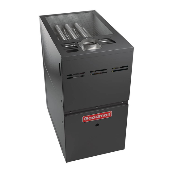
33-3/8" 80% Gas Furnace
•
Refer to current Service Manual RS6610004 for installation, operation, and troubleshooting information.
•
All safety information must be followed as provided in the Service Manual.
•
Refer to the appropriate Parts Catalog for part number information.
•
Model numbers listed on page 3.
This manual is to be used by qualified, professionally trained HVAC technicians only.
Goodman does not assume any responsibility for property damage or personal injury due
to improper service procedures or services performed by an unqualified person.
TECHNICAL MANU
TECHNICAL MANU
TECHNICAL MANU AL
TECHNICAL MANU
TECHNICAL MANU
GME8
Upflow/Horizontal
Copyright ©2009-2010 Goodman
Manufacturing Company, L.P.
AL
AL
AL
AL
®
C
US
RT6621020 Rev. 1
April 2010
Advertisement
Table of Contents

Related Manuals for Goodman UPFLOW/HORIZONTAL GME8


Summary of Contents for Goodman UPFLOW/HORIZONTAL GME8
- Page 1 33-3/8" 80% Gas Furnace Upflow/Horizontal • Refer to current Service Manual RS6610004 for installation, operation, and troubleshooting information. • All safety information must be followed as provided in the Service Manual. • Refer to the appropriate Parts Catalog for part number information.
-
Page 2: Product Identification
PRODUCT IDENTIFICATION The model and manufacturing number are used for positive identification of component parts used in manufacturing. Please use these numbers when requesting service or parts information. BRAND: ® G: Goodman Brand FURNACE TYPE E: Two-Stage w/X-13 Motor SUPPLY TYPE:... - Page 3 PRODUCT IDENTIFICATION The model and manufacturing number are used for positive identification of component parts used in manufacturing. Please use these numbers when requesting service or parts information. The United States Environmental Protection Agency (“EPA”) has issued various regulations re- WARNING WARNING garding the introduction and disposal of refrigerants introduced into this unit.
-
Page 4: Product Design
This furnace is also equipped with a self-diagnosing elec- tronic control module. In the event a furnace component is not operating properly, the control module LED will flash on and off in a factory-programmed sequence, depending on the problem encountered. - Page 5 ORIFICE HA-02 HIGH ALTITUDE CONVERSION KIT REQUIRED Tabled data is based upon the furnace input being reduced for altitudes above sea level. U.S. 4% per 1,000 feet. Canada 10% derate for 2,000-4,000 feet. High altitude kits are purchased according to the installa- tion altitude and usage of either natural or propane gas.
-
Page 6: Product Dimensions
PRODUCT DIMENSIONS GME80703BXC* GME80905CXC* GME81155CXC* All dimensions are in inches. GME8*****XA UNITS 17.5 19.5 33-3/8 33-3/8... - Page 7 PRODUCT DESIGN * All installas above 7,000 ft. require a pressure switch change. For installations in Canada, the GME8 furnace is certified only to 4,500 ft. * Negative pressure readings are in inches of water column (*w.c.) ROLLOUT LIMIT SWITCHES Part Number Open Setting (°F)
- Page 8 • All CAPF coils have a CAUF equivalent. • All CHPF coils in B, C & D heights have an insulated Z bracket for use with one size smaller furnace. • All proper coil combinations are subject to being AHRI rated with a matched outdoor unit.
- Page 9 NOTE: Complete lineup of thermostats can be found in the Thermostat Specification Sheets. Filters: Filters are required with this furnace and must be provided by the installer. The filters used must comply with UL900 or CAN/ULCS111 standards. Installing this furnace without filters will void the unit warranty.
- Page 10 To change from the factory single-stage operation, adjust the dipswitches on the ignition control as follows: Mode 5 Min Fixed Auto Note: This furnace is designed to be used with a single-stage room thermostat. Safety Circuit Check Low-Heat Blower Delay Time (5 Min)
-
Page 11: Furnace Specifications
These furnaces are manufactured for natural gas operation. Optional Kits are available for conversion to propane gas operation. For elevations above 2000 ft. the rating should be reduced by 4% for each 1000 ft. above sea level. The furnace must not be derated, orifice changes should only be made if necessary for altitude. -
Page 12: Blower Performance Specifications
GME8 1155CXC* CFM in chart is without filters(s). Filters do not ship with this furnace, but must be provided by the installer. All furnaces ship as high speed cooling. Installer must adjust blower cooling speed as needed. For most jobs, about 400 CFM per ton when cooling is desirable. - Page 13 BLOWER PERFORMANCE SPECIFICATIONS RISE TEMPERATURE...
-
Page 14: Wiring Diagrams
1. SET HEAT ANTICIPATOR ON ROOM THERMOSTAT AT 0.7 AMPS. 2. MANUFACTURER'S SPECIFIED REPLACEMENT PARTS MUST BE USED WHEN SERVICING. 3. IF ANY OF THE ORIGINAL WIRE AS SUPPLIED WITH THE FURNACE MUST BE REPLACED, IT MUST BE REPLACED WITH WIRING MATERIAL HAVING A TEMPERATURE °C. - Page 15 2. MANUFACTURER'S SPECIFIED REPLACEMENT PARTS MUST BE USED WHEN SERVICING. 3. IF ANY OF THE ORIGINAL WIRE AS SUPPLIED WITH THE FURNACE MUST BE REPLACED, IT MUST BE REPLACED WITH WIRING MATERIAL HAVING A TEMPERATURE RATING OF AT LEAST 105 °C. USE COPPER 4.
- Page 16 SCHEMATICS CIRCULATOR BLOWER HEAT HEAT COOL .0005 FLAME SENSOR PROBE IGNITOR WR 50M56-289 INTEGRATED IGNITION CONTROL This schematic is for reference only. Not all wiring is as shown above. Always refer to the appropriate wiring diagram for the unit being serviced. HIGH VOLTAGE! DISCONNECT ALL POWER BEFORE SERVICING OR INSTALLING THIS UNIT.
Need help?
Do you have a question about the UPFLOW/HORIZONTAL GME8 and is the answer not in the manual?
Questions and answers