Table of Contents
Advertisement
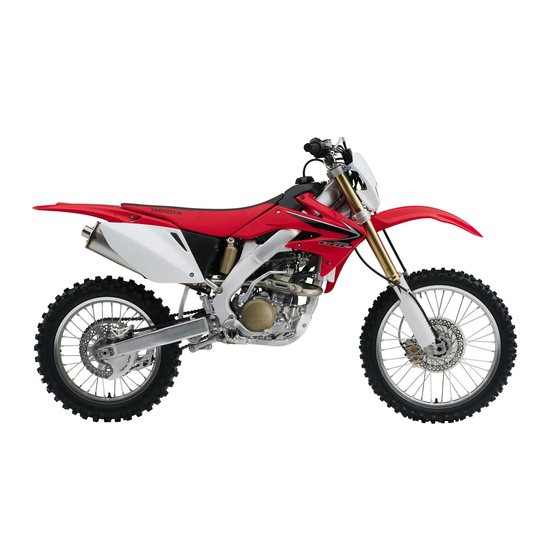
CRF250X
© Honda Motor Co., Ltd. 2008
CRF250X_COVER
1
OWNER'S MANUAL & COMPETITION HANDBOOK
MANUEL DU CONDUCTEUR ET DE COMPETITION
FAHRER-HANDBUCH und WETTBEWERBSANLEITUNG
INSTRUCTIEBOEK JE & WEDSTRIJDHANDBOEK
MANUAL DEL PROPIETARIO Y GUÍA DE COMPETICIONES
MANUALE D'USO E DEGLI ASSETTI DA COMPETIZIONE
3/7/08, 10:42
HONDA O/M CRF250X(Eu) 3RKSC620 00X3R-KSC-6200
E
F
G
D
S
I
Advertisement
Chapters
Table of Contents

Related Manuals for Honda CRF250X


Summary of Contents for Honda CRF250X
- Page 1 MANUEL DU CONDUCTEUR ET DE COMPETITION FAHRER-HANDBUCH und WETTBEWERBSANLEITUNG INSTRUCTIEBOEK JE & WEDSTRIJDHANDBOEK MANUAL DEL PROPIETARIO Y GUÍA DE COMPETICIONES MANUALE D’USO E DEGLI ASSETTI DA COMPETIZIONE © Honda Motor Co., Ltd. 2008 CRF250X_COVER 3/7/08, 10:42 HONDA O/M CRF250X(Eu) 3RKSC620 00X3R-KSC-6200...
- Page 2 This manual should be considered a permanent part of the motorcycle and should remain with the motorcycle when it is resold. All information in this publication is based on the latest product information available at the time of approval for printing. Honda Motor Co., Ltd.
- Page 3 250X_ Contents.qxd 08.7.3 10:07 ページ85 Honda CRF250X OWNER’S MANUAL & COMPETITION HANDBOOK...
- Page 4 250X_ Contents.qxd 08.7.3 10:07 ページ86 Introduction Congratulations on choosing your Honda CRF There are responsibilities, restrictions, and This motorcycle has no cooling fan. For this off-road motorcycle. exclusions which apply to this warranty. Please reason, engine overheating and coolant loss will read the Honda Motorcycle Warranties Booklet occur if the engine is kept idling too long when When you own a Honda, you’re part of a...
- Page 5 250X_ Contents.qxd 08.7.3 10:07 ページ87 A Few Words About Safety Your safety, and the safety of others, is very important. And operating this motorcycle safely is an important responsibility. To help you make informed decisions about safety, we have provided operating procedures and other information on labels and in this manual. This information alerts you to potential hazards that could hurt you or others.
-
Page 6: Table Of Contents
250X_ Contents.qxd 08.7.3 10:07 ページ88 Contents MOTORCYCLE SAFETY.......1 Service Procedures Tyre Selection for Track Conditions ....137 Important Safety Information......2 Fluids & Filters Personal Fit Adjustments ........138 Important Safety Precautions......2 Fuel System............40 Loading..............3 Engine Oil ............43 TIPS ..............139 Accessories & Modifications ......4 Transmission Oil ..........46 Transporting Your Motorcycle ......140 Safety Labels............5... -
Page 7: Motorcycle Safety
250X_001-029.qxd 08.7.3 10:08 ページ1 Motorcycle Safety This section presents some of the most important Important Safety Information.......2 information and recommendations to help you Important Safety Precautions......2 ride your CRF safely. Please take a few Loading..............3 moments to read these pages. This section also Accessories &... -
Page 8: Important Safety Information
250X_001-029.qxd 08.7.3 10:08 ページ2 Important Safety Information Do not wear loose clothing which could catch on Keep Your Honda In Safe Condition. It’s Important Safety Precautions the control levers, kickstarter, footpegs, drive important to keep your CRF properly maintained chain, or wheels. and in safe riding condition. -
Page 9: Loading
250X_001-029.qxd 08.7.3 10:08 ページ3 Loading Your CRF was designed as a rider-only Loading Guidelines motorcycle. It was not designed to carry a As discussed on page 2, we recommended that passenger or cargo. A passenger or cargo could you do not carry any cargo on this motorcycle. interfere with your ability to move around to However, if you decide to carry cargo, ride at maintain your balance and control of the CRF. -
Page 10: Accessories & Modifications
250X_001-029.qxd 08.7.3 10:08 ページ4 Accessories & Modifications Accessories Modifications Accessories & Modifications We strongly recommend that you use only Honda We strongly advise you not to remove any Genuine accessories that have been specifically original equipment or modify your CRF in any designed and tested for your CRF. -
Page 11: Safety Labels
250X_001-029.qxd 08.7.3 10:08 ページ5 Safety Labels This page shows the locations of safety labels on your CRF. Some labels warn you of potential hazards that could cause serious injury. Others provide important safety information. Read these labels carefully and don’t remove them. If the label comes off or becomes hard to read, contact your Honda dealer for replacement. - Page 12 250X_001-029.qxd 08.7.3 10:08 ページ6 Motorcycle Safety...
-
Page 13: Operating Controls
250X_001-029.qxd 08.7.3 10:08 ページ7 Operating Controls Read this section carefully before you ride. It Operation Component Locations ......8 presents the location of the basic controls on your CRF. Operating Controls... -
Page 14: Operation Component Locations
250X_001-029.qxd 08.7.3 10:08 ページ8 Operation Component Locations hot start lever tripmeter clutch lever front brake lever start button throttle grip engine stop button choke knob kickstarter rear brake pedal fuel valve shift lever Operating Controls... -
Page 15: Before Riding
250X_001-029.qxd 08.7.3 10:08 ページ9 Before Riding Before each ride, you need to make sure you and Are You Ready to Ride?........10 your Honda are both ready to ride. To help get Is Your Motorcycle Ready to Ride?....11 you prepared, this section discusses how to Pre-ride Inspection ...........11 evaluate your riding readiness, and what items you should check on your CRF. -
Page 16: Are You Ready To Ride
250X_001-029.qxd 08.7.3 10:08 ページ10 Are You Ready to Ride? Before riding your CRF for the first time, we WARNING recommend that you read this owner’s manual, make sure you understand the safety messages, Not wearing a helmet increases the and know how to operate the controls. chance of serious injury or death in a crash. -
Page 17: Is Your Motorcycle Ready To Ride
250X_001-029.qxd 08.7.3 10:08 ページ11 Is Your Motorcycle Ready to Ride? Competitive riding can be tough on a motorcycle, Pre-ride Inspection so it’s important to inspect your CRF and correct any problems you find before each ride. Check the following items (page numbers are at the Check the following before each ride: right): •... - Page 18 250X_001-029.qxd 08.7.3 10:08 ページ12 Before Riding...
-
Page 19: Basic Operating Instructions
250X_001-029.qxd 08.7.3 10:08 ページ13 Basic Operating Instructions This section gives basic information on how to Safe Riding Precautions........14 start and stop your engine as well as break-in Side Stand .............14 guidelines. Tripmeter............14 Starting & Stopping the Engine ......15 Preparation ............15 Fuel Valve .............15 Starting Procedure ........15 Flooded Engine ..........16... -
Page 20: Safe Riding Precautions
250X_001-029.qxd 08.7.3 10:08 ページ14 Basic Operating Instructions Side Stand Safe Riding Precautions Tripmeter The side stand (1) is used to support your CRF Before riding your CRF for the first time, please The tripmeter (1) is used to record the distance while parked (page 19). -
Page 21: Starting & Stopping The Engine
250X_001-029.qxd 08.7.3 10:08 ページ15 Starting & Stopping the Engine Always follow the proper starting procedure 5. Warm up the engine; don’t operate the Starting Procedure throttle. described below. 6. About 15 seconds after the engine starts, push the choke knob all the way to fully OFF. If Your CRF can be started with the transmission in Always follow the proper starting procedure idling is unstable, open the throttle slightly. -
Page 22: Flooded Engine
250X_001-029.qxd 08.7.3 10:08 ページ16 Starting & Stopping the Engine Flooded Engine How to Stop the Engine Starting the engine after a stall during riding or after a fall 1. Shift the transmission into neutral. 2. Pull the hot start lever all the way in and start the engine. -
Page 23: Shifting Gears
250X_001-029.qxd 08.7.3 10:08 ページ17 Shifting Gears Remember to close the throttle and pull the clutch lever in completely before shifting. NOTICE Improper shifting may damage the engine, transmission, and drive train. Learning when to shift gears comes with experience. Upshift to a higher gear or reduce throttle before engine min (rpm) (speed) gets too high. -
Page 24: Braking
250X_001-029.qxd 08.7.3 10:08 ページ18 Braking To slow or stop, apply the front brake lever and When descending a long, steep grade, use engine rear brake pedal smoothly, while downshifting to compression braking by downshifting, with match your speed. Gradually increase braking as intermittent use of both brakes. -
Page 25: Parking
250X_001-029.qxd 08.7.3 10:08 ページ19 Parking Lower the side stand to support your CRF. If you’re through riding for the day, turn the fuel valve OFF. Always choose a level surface to park. Basic Operating Instructions... -
Page 26: Post-Ride Inspection
250X_001-029.qxd 08.7.3 10:08 ページ20 Post-ride Inspection When you return home after riding, thoroughly clean your CRF and remove any dirt, mud, brush, rocks or other objects you may have picked up along the way. After cleaning, carefully inspect your CRF for leaks or damage. -
Page 27: Break-In Guidelines
250X_001-029.qxd 08.7.3 10:08 ページ21 Break-in Guidelines Help assure your CRF’s future reliability and performance by paying extra attention to how you ride during the first operating day or 25 km (15 miles). During this period, avoid full-throttle starts and rapid acceleration. This same procedure should be followed each time when: •... - Page 28 250X_001-029.qxd 08.7.3 10:08 ページ22 Basic Operating Instructions...
-
Page 29: Servicing Your Honda
250X_001-029.qxd 08.7.3 10:08 ページ23 Servicing Your Honda Keeping your CRF well maintained is absolutely Before You Service Your Honda Chassis essential to your safety. It’s also a good way to The Importance of Maintenance ......24 Suspension............82 protect your investment, get Maintenance Safety ..........25 Front Suspension Inspection......82 maximum performance, avoid breakdowns, and... -
Page 30: The Importance Of Maintenance
250X_001-029.qxd 08.7.3 10:08 ページ24 The Importance of Maintenance A well-maintained motorcycle is essential for WARNING safe, economical, and trouble-free riding. It will also help reduce air pollution. Careful pre-ride Improperly maintaining this motorcycle or inspections and good maintenance are especially failing to correct a problem before you important because your CRF is designed to be ride can cause a crash in which you can... -
Page 31: Maintenance Safety
250X_001-029.qxd 08.7.3 10:08 ページ25 Maintenance Safety This section includes instructions on how to • Read the instructions before you begin, and Important Safety Precautions perform some important maintenance tasks. make sure you have the tools and skills Some of the most important safety precautions required. -
Page 32: Maintenance Schedule
250X_001-029.qxd 08.7.3 10:08 ページ26 Maintenance Schedule To maintain the safety and reliability of your Perform the pre-ride inspection (page 11) at each CRF, regular inspection and service is required scheduled maintenance period. as shown in the Maintenance Schedule that follow. Summary of Maintenance Schedule Notes and Procedures: The Maintenance Schedule lists items that can be... - Page 33 250X_001-029.qxd 08.7.3 10:08 ページ27 Maintenance Schedule Damage from competition use is not covered by the Distributor’s Limited Warranty on your Honda. Perform the Pre-ride Inspection (page 11) at each scheduled maintenance period. I: Inspect and Clean, Adjust, Lubricate or Replace if necessary. C: Clean. A: adjust. L: Lubricate. R: Replace. FREQUENCY About About...
-
Page 34: General Competition Maintenance
250X_001-029.qxd 08.7.3 10:08 ページ28 General Competition Maintenance Perform maintenance on firm, level ground using the side stand, a workstand, or equivalent support. When tightening bolts, nuts or screws, start with the larger diameter or inner fasteners, and tighten them to the specified torque using a crisscross pattern. - Page 35 250X_001-029.qxd 08.7.3 10:08 ページ29 General Competition Maintenance Spark Plug Air Cleaner Some non-resistor plugs may cause ignition problems. Refer Clean and oil your air cleaner regularly because the volume to the recommendations elsewhere in this manual for specific of air able to pass through it has a great effect on types so you will be sure to use the proper reach and heat performance.
- Page 36 250X_030-059.qxd 08.7.3 10:09 ページ30 General Competition Maintenance Handgrips Fuel Filter Fuel Contamination Always use Hand Grip Cement when replacing handgrips. Periodically drain the fuel from the fuel tank, remove and clean Refer to Fuel System, in your Owner’s Manual (page 41). the fuel valve and fuel filter.
- Page 37 250X_030-059.qxd 08.7.3 10:09 ページ31 General Competition Maintenance Suspension Linkage Lubrication Fuse Steering Head Bearings Disassemble, clean, inspect and lubricate all suspension Check the fuse before looking elsewhere for the cause of an Periodically clean, inspect and regrease the steering head linkage pivot bearings with grease after each 7.5 hours of electrical problem.
-
Page 38: Before & After Competition Maintenance
250X_030-059.qxd 08.7.3 10:09 ページ32 Before & After Competition Maintenance Between Motos & Practice Maintenance After Competition Maintenance After practice or between motos you have a It is important to the long term performance of chance to make additional checks and your CRF to practice a consistent adjustments. - Page 39 250X_030-059.qxd 08.7.3 10:09 ページ33 Before & After Competition Maintenance Routine Cleaning If your CRF is only slightly dirty, it is best to clean it by hand with the aid of a stiff bristled nylon brush and some clean rags. Take care to prevent catching your fingers between the chain and sprocket.
-
Page 40: Maintenance Component Locations
250X_030-059.qxd 08.7.3 10:10 ページ34 Maintenance Component Locations hot start lever front brake fluid reservoir front brake lever clutch lever throttle grip radiator cap fuel fill cap rear suspension front suspension compression damping rebound damping rear suspension high speed adjuster adjuster spark plug coolant reserve tank throttle stop screw... -
Page 41: Seat Removal
250X_030-059.qxd 08.7.3 10:10 ページ35 Seat Removal Refer to Safety Precautions on page 25. Installation 1. Install the seat while aligning the seat front Removal prong (3) with the seat bracket (4) and seat 1. Remove the seat mounting bolts (1). rear prong (5) with the tab (6) of the frame. -
Page 42: Fuel Tank Removal
250X_030-059.qxd 08.7.3 10:10 ページ36 Fuel Tank Removal Refer to Safety Precautions on page 25. 5. Pull the breather tube (4) out of steering stem 9. Disconnect the fuel line (8) from the fuel valve (9). The fuel line leading to the nut. - Page 43 250X_030-059.qxd 08.7.3 10:10 ページ37 Fuel Tank Removal Installation 8. Install the shrouds (8) and shroud B bolts/ 1. Install the fuel tank on the frame. collars (9). 2. Install the fuel valve (1) and tighten fuel valve Tighten the shroud B bolts to the specified bolt (2).
-
Page 44: Subframe Upright Position
250X_030-059.qxd 08.7.3 10:10 ページ38 Subframe Upright Position Refer to Safety Precautions on page 25. 4. Remove the muffler (page 62). 7. Loosen the subframe mounting upper bolt 5. Remove the wire band (12). (15) and remove the subframe mounting lower The subframe may be adjusted to an upright bolts (16). - Page 45 250X_030-059.qxd 08.7.3 10:10 ページ39 Subframe Upright Position Installation 7. Install the seat (8) (page 35). 4. Tighten the screw (5) on the air cleaner 1. Loosen the subframe mounting upper bolt (1). connecting tube clamp (6). 8. Install the left side cover (9), seat mounting 2.
-
Page 46: Fuel System
250X_030-059.qxd 08.7.3 10:10 ページ40 Fuel System Refer to Safety Precautions on page 25. WARNING Refueling Procedure Petrol is highly flammable and Fuel Recommendation explosive. You can be burned or Fuel Tank Capacity: 7.3R(1.93 US gal, 1.61 seriously injured when handling fuel. Imp gal) Reserve Capacity: 1.6R (0.42 US gal, 0.35 Type... - Page 47 250X_030-059.qxd 08.7.3 10:10 ページ41 Fuel System 1. Check for leaks. Fuel Line Fuel Filter 2. Check the fuel line (1) for cracks, deterioration, damage or leakage. Replace the fuel line, if necessary. The fuel filter is mounted on the bottom left side of the fuel tank.
- Page 48 250X_030-059.qxd 08.7.3 10:10 ページ42 Fuel System 4. Wash the fuel filter (3) in high flash-point cleaning solvent. 5. Check that the O-ring (4) is in good condition and install it onto the fuel joint. Install the fuel filter in the fuel tank by tightening the bolts to the specified torque: 10 N·m (1.0 kgf·m, 7 lbf·ft) Refill the fuel tank.
-
Page 49: Engine Oil
250X_030-059.qxd 08.7.3 10:10 ページ43 Engine Oil Refer to Safety Precautions on page 25. • Your CRF does not need oil additives. JASO T 903 standard Use the recommended oil. The JASO T 903 standard is an index for engine Using the proper oil, and regularly checking, •... - Page 50 250X_030-059.qxd 08.7.14 14:51 ページ44 Engine Oil Checking & Adding Oil Changing Engine Oil & Filter 1. Run the engine at idle for 3 minutes, then shut it off. 2. Support the CRF in an upright position on a level surface. 3.
- Page 51 250X_030-059.qxd 08.7.3 10:10 ページ45 Engine Oil 8. Remove the left engine guard bolt (4) and left 18.Install the engine oil filler cap/dipstick. NOTICE engine guard (5). 19.Check the engine oil level by following the Using the wrong oil filter may result in leaks or steps in Checking &...
-
Page 52: Transmission Oil
250X_030-059.qxd 08.7.3 10:10 ページ46 Transmission Oil Refer to Safety Precautions on page 25. • Your CRF does not need oil additives. JASO T 903 standard Use the recommended oil. The JASO T 903 standard is an index for engine Using the proper oil, and regularly checking, •... - Page 53 250X_030-059.qxd 08.7.14 14:29 ページ47 Transmission Oil 6. Fill the crankcase with recommended oil. Checking & Adding Oil Replacing Transmission Oil Capacity: 0.67R(0.71 US qt, 0.59 Imp qt) after oil change 7. Check the transmission oil level by following 1. Run the engine at idle for 3 minutes, then shut it off.
-
Page 54: Coolant
250X_030-059.qxd 08.7.3 15:23 ページ48 Coolant Your CRF’s liquid cooling system Increasing the concentration of antifreeze is not 2. Open the air cleaner housing cover (4) by dissipates engine heat through the coolant jacket recommended because it decreases cooling turning the quick fastener (5) that surrounds the cylinder and cylinder head. - Page 55 250X_030-059.qxd 08.7.3 10:10 ページ49 Coolant 4. Add coolant to the reserve tank as require to Cooling System Inspection bring the coolant level to the UPPER level mark. 5. Install the reserve tank cap (10). 1. Check the cooling system for leaks (see the 6.
- Page 56 250X_030-059.qxd 08.7.3 10:10 ページ50 Coolant 3. Turn the quick fastener (2) counterclockwise Coolant Replacement Coolant System Bleed Air and open the air cleaner housing cover (3). 4. Remove the left side cover bolt (4), collar (5), Refer to Safety Precautions on page 25. seat mounting bolt (6) and left side cover (7).
-
Page 57: Air Cleaner
250X_030-059.qxd 08.7.3 15:23 ページ51 Air Cleaner Refer to Safety Precautions on page 25. 3. Pull the air cleaner element (5) out from the Cleaning air cleaner holder (6). The air cleaner uses polyurethane inner and outer pieces which can’t be separated. 1. - Page 58 250X_030-059.qxd 08.7.3 15:23 ページ52 Air Cleaner 7. Apply a thin coat of Honda White Lithium NOTICE Grease or equivalent to the sealing surface. 8. Assemble the air cleaner element and holder. Improper installation of the air cleaner assembly Install the tab (7) of the holder in the hole (8) may allow dirt and dust to enter the engine and of the air cleaner tab (9).
-
Page 59: Crankcase Breather
250X_030-059.qxd 08.7.3 10:10 ページ53 Crankcase Breather Refer to Safety Precautions on page 25. Crankcase Breather Service more frequently if your CRF is ridden in the rain or often at full throttle. Service the breather if you can see deposits in the transparent section of the drain tube. -
Page 60: Throttle
250X_030-059.qxd 08.7.3 10:10 ページ54 Throttle Lower Adjustment Refer to Safety Precautions on page 25. 1. Pull the dust cover (2) back. The lower adjuster is used for major freeplay 2. Loosen the upper lock nut (3). adjustment, such as after replacing the throttle 3. - Page 61 250X_030-059.qxd 08.7.3 10:10 ページ55 Throttle Throttle Inspection (1) throttle 1. Check that the throttle assembly is positioned properly and the securing bolts are tight. 2. Check for smooth rotation of the throttle (1) from fully open to fully closed in all steering positions.
-
Page 62: Clutch System
250X_030-059.qxd 08.7.3 10:10 ページ56 Clutch System Refer to Safety Precautions on page 25. Cable End Adjustment Integral Cable Adjustment The integral cable adjuster is used if the cable Minor adjustments are generally made with the clutch cable end adjuster. end adjuster is threaded out near its limit, or if Clutch Freeplay the correct freeplay cannot be obtained. - Page 63 250X_030-059.qxd 08.7.3 10:10 ページ57 Clutch System 5. Remove the clutch pressure plate (9). Other Inspections & Lubrication Clutch Cover/Disc/Plate Removal • Check that the clutch lever assembly is 1. Drain the transmission oil (page 47). positioned properly (the end of the holder (1) 2.
- Page 64 250X_030-059.qxd 08.7.3 10:10 ページ58 Clutch System Clutch Disc/Plate Inspection Clutch Disc/Plate Installation Clutch Spring Inspection 1. Install the spring seat (1) and judder spring (2) Replace the clutch discs (1) if they show signs of onto the clutch centre as shown. scoring or discolouration.
- Page 65 250X_030-059.qxd 08.7.14 14:29 ページ59 Clutch System 5. Install the clutch pressure plate (7). 10.Apply grease to the rear brake pedal pivot bolt sliding surface. 6. Install the five clutch springs and clutch spring bolts (8). 11. Install the rear brake pedal (11), dust seals (12), washer (13) and pivot bolt (14) and 7.
-
Page 66: Hot Start Lever
250X_030-059.qxd 08.7.3 10:10 ページ60 Hot Start Lever Refer to Safety Precautions on page 25. Adjustment Adjustments can be made with the cable end adjuster. Hot Start Lever Freeplay Loosen the lock nut (3) and turn the adjuster (4). Turning the adjuster in direction (+) will increase freeplay and turning it in direction (–) will decrease freeplay. -
Page 67: Spark Plug
250X_060-083.qxd 08.7.3 10:11 ページ61 Spark Plug Refer to Safety Precautions on page 25. 7. To obtain accurate spark plug readings, Spark Plug Inspection & Replacement accelerate up to speed on a straightaway. Push the engine stop button and disengage the Spark Plug Recommendation clutch by pulling the lever in. -
Page 68: Exhaust Pipe/Muffler
250X_060-083.qxd 08.7.3 10:11 ページ62 Exhaust Pipe/Muffler 2. Loosen the muffler clamp bolt (5). Exhaust Pipe/Muffler Inspection Muffler Removal 3. Remove the muffler A bolt/washer (6), muffler B bolt (7) and muffler (8). Check the flange bolts for tightness. 1. Remove the seat mounting bolt (1), side cover Check the exhaust pipe and muffler for cracks or bolt (2), collar (3) and right side cover (4). - Page 69 250X_060-083.qxd 08.7.3 10:11 ページ63 Exhaust Pipe/Muffler 5. Tighten the muffler B bolt (6) and muffler A 7. Install the right side cover (9), collar (10) and Muffler Installation bolt/washer (7) to the specified torque: side cover bolt (11). 26 N·m (2.7 kgf·m, 19 lbf·ft) 8.
- Page 70 250X_060-083.qxd 08.7.3 10:11 ページ64 Exhaust Pipe/Muffler Exhaust Pipe Removal Exhaust Pipe Installation 1. Remove the muffler (page 62). 1. Install a new exhaust pipe gasket (1), exhaust 2. Remove the exhaust pipe joint nuts (1), pipe (2) and exhaust pipe joint nuts (3) and exhaust pipe (2) and exhaust pipe gasket (3).
-
Page 71: Spark Arrester
250X_060-083.qxd 08.7.3 10:11 ページ65 Spark Arrester 3. Use a brush to remove carbon deposits from Spark Arrester Inspection the spark arrester screen. Be careful to avoid damaging the spark arrester screen. The spark arrester must be free of brakes and holes. The spark arrester must be serviced every 1,600 km (1,000 mi) of running or 100 operating hours Replace, if necessary. -
Page 72: Valve Clearance
250X_060-083.qxd 08.7.3 10:11 ページ66 Valve Clearance Refer to Safety Precautions on page 25. Cylinder Head Cover Removal Positioning At Top Dead Centre On The Compression Stroke Excessive valve clearance will cause noise and eventual engine damage. Little or no clearance Before inspection, clean the engine thoroughly to will prevent the valve from closing and cause keep dirt from entering the engine. - Page 73 250X_060-083.qxd 08.7.3 10:11 ページ67 Valve Clearance 3. Rotate the crankshaft by turning the primary 2. Measure the exhaust valve clearance by Valve Clearance Inspection drive gear bolt (2) clockwise until aligning the inserting a feeler gauge (1) between the punch mark (3) on the primary drive gear with exhaust rocker arm (4) and shims (5).
- Page 74 250X_060-083.qxd 08.7.3 10:11 ページ68 Valve Clearance 2. Remove the cam chain tensioner lifter cover Use the tensioner stopper tool. Camshaft Removal bolt (1) and sealing washer (2). • Tensioner stopper 070MG-0010100 3. Turn the tensioner shaft clockwise with the 1. Record the intake valve clearance and exhaust valve clearance (page 67).
- Page 75 250X_060-083.qxd 08.7.3 10:11 ページ69 Valve Clearance 4. Remove the camshaft holder bolts (4) and 6. Remove the valve lifters (7). 7. Remove the shims (8). camshaft holders (5). Position the removed intake valve lifters and Loosen the camshaft holder bolts in a criss-cross shims to indicate their location such as intake or pattern in two or three steps.
- Page 76 250X_060-083.qxd 08.7.3 10:11 ページ70 Valve Clearance 2. Measure the shim thickness with a micrometer 3. Calculate the new shim thickness using the Shim Selection and record it. equation below. Sixty-nine different thickness shims (2) are A = (B – C) + D available from the thinnest (1.200 mm 1.
- Page 77 250X_060-083.qxd 08.7.3 10:11 ページ71 Valve Clearance 3. Rotate the primary drive gear bolt (4) 5. Apply grease to the set rings and install it Camshaft Installation (crankshaft) clockwise and align the punch onto the camshaft holders (13). mark (5) with the “ ” mark (6). Apply oil to the camshaft holder bolt threads and seating surface.
- Page 78 250X_060-083.qxd 08.7.3 15:07 ページ72 Valve Clearance 6. Insert the feeler gauge between the intake 7. Remove the stopper tool (16) from the cam Crankshaft Hole Cap Installation valve lifter and cam lobe. chain tensioner lifter. If the feeler gauge (15) cannot be inserted, the shim is caught between the valve lifter and the Coat a new O-ring (1) with engine oil and install valve retainer.
- Page 79 250X_060-083.qxd 08.7.3 10:11 ページ73 Valve Clearance 3. Check the rubber seals (5) are in good 5. Remove the spark plug (page 61). Cylinder Head Cover Installation condition, replace them if necessary. 6. Connect the direct ignition coil (8) and Install the rubber seals onto the cylinder head breather tube (9).
-
Page 80: Piston/Piston Rings/Piston Pin
250X_060-083.qxd 08.7.3 10:11 ページ74 Piston/Piston Rings/Piston Pin 8. Disconnect the direct ignition coil (1). 12.Position the piston to top dead centre on the Cylinder Head Removal 9. Remove any dirt around the spark plug base. compression stroke (page 66). Remove the camshaft (page 68). 13.Loosen the radiator hose clamp (3) and 1. - Page 81 250X_060-083.qxd 08.7.3 10:11 ページ75 Piston/Piston Rings/Piston Pin 14.Remove the engine hanger nuts/bolts (5), 15.Remove the cylinder head bolts (8). 18.Remove the dowel pins (12), cylinder head engine hanger plates (6), and clutch cable 16.Loosen the cylinder bolt (9). gasket (13) and cam chain guide (14). guide (7).
- Page 82 250X_060-083.qxd 08.7.3 10:11 ページ76 Piston/Piston Rings/Piston Pin 4. Spread each piston ring (4) and remove by Cylinder Removal Piston Removal lifting it up at a point just opposite the gap. 1. Remove the cylinder bolt (1) and cylinder (2). 1. Place clean shop towels in the crankcase to NOTICE keep the piston pin clips, or other parts, from falling into the crankcase.
- Page 83 250X_060-083.qxd 08.7.3 10:11 ページ77 Piston/Piston Rings/Piston Pin top ring Piston/Piston Pin/Piston Ring Inspection Piston Ring Installation We recommend you consult the Shop Manual or 1. Remove the carbon deposits from the piston oil ring your authorized Honda dealer for correct Service crown and piston ring grooves with the Limit measurements.
- Page 84 250X_060-083.qxd 08.7.3 10:11 ページ78 Piston/Piston Rings/Piston Pin Piston Installation Cylinder Installation 1. Place clean shop towels over the crankcase 1. Place clean shop towels over the crankcase opening to keep the piston pin clips from opening to prevent dust or dirt from entire the falling into the crankcase.
- Page 85 250X_060-083.qxd 08.7.3 10:11 ページ79 Piston/Piston Rings/Piston Pin 6. Apply clean engine oil to the cylinder wall, 7. Install the cam chain guide (6) and fit the cam Cylinder Head Installation piston outer surface and piston rings. chain guide tabs (7) in the cylinder cut-outs (8). Route the cam chain (3) through the cylinder (4).
- Page 86 250X_060-083.qxd 08.7.3 10:12 ページ80 Piston/Piston Rings/Piston Pin 2. Route the cam chain through the cylinder 4. Install the cylinder bolt (5), cylinder head 5. Install the engine hanger plates (7), clutch head (3). bolts (6) and tighten them to the specified cable guide (8), engine hanger nuts/bolts (9) Install the cylinder head.
- Page 87 250X_060-083.qxd 08.7.3 10:12 ページ81 Piston/Piston Rings/Piston Pin 6. Connect the radiator hose (11) to the cylinder 9. Install the cylinder head cover (page 73). head and tighten the radiator hose clamp (12) Connect the direct ignition coil (13). securely. (13) (12) (11) (13) direct ignition coil...
-
Page 88: Suspension
250X_060-083.qxd 08.7.3 10:12 ページ82 Suspension Refer to Safety Precautions on page 25. • Refer to Suspension Adjustment Guidelines (page 125). Make all rebound and 1.5 mm (0.06 in) Loose, worn, or damaged suspension components compression damping adjustments in one- may adversely affect the handling and stability of click increments. -
Page 89: Rear Suspension Inspection
250X_060-083.qxd 08.7.3 10:12 ページ83 Suspension 1. Bounce the rear of the motorcycle up and down Rear Suspension Inspection and check for smooth suspension action. The swingarm is controlled by one hydraulic shock absorber with an aluminum reservoir for oil and nitrogen gas pressure. The gas pressure in the reservoir is contained within a rubber bladder. -
Page 90: Recommended Fork Oil
250X_084-103.qxd 08.7.3 10:13 ページ84 Suspension 4. Drain the fork oil by turning the outer tube (1) NOTICE Recommended Fork Oil upside down. (About 12 cm (0.4 US oz, The outer tube (1) can drop on the slider (7) and 0.4 Imp oz) of fork oil will be left in the outer damage the fork dust seal (5) and guide bushing tube when it is left inverted for about 20 (6) when the fork damper is removed. - Page 91 250X_084-103.qxd 08.7.3 15:12 ページ85 Suspension 5. Pour the recommended fork oil (page 84) into 6. Check that the O-ring (10) on the fork damper Optional Softer 3.92 N/mm (22.38 lbf/in) Fork Spring the outer tube. (2) is in good condition. Apply the recommended fork oil to the O-ring.
-
Page 92: Brakes
250X_084-103.qxd 08.7.14 14:32 ページ86 Brakes Refer to Safety Precautions on page 25. Front Brake Lever Adjustment Rear Brake Pedal Height Both the front and rear brakes are the hydraulic disc type. As the brake pads wear, the brake The rear brake pedal height should be fluid level will drop. - Page 93 250X_084-103.qxd 08.7.3 10:13 ページ87 Brakes Rear Brake Fluid Level Check Fluid Level Inspection Front Brake Fluid Level Check (2) LOWER level mark With the motorcycle in an upright position, check (1) LWR (LOWER) level mark the fluid level. It should be above the LOWER level mark (2). If With the motorcycle in an upright position, check the level is at or below the LOWER level mark, the fluid level.
- Page 94 250X_084-103.qxd 08.7.3 10:13 ページ88 Brakes Adding Front Brake Fluid Adding Rear Brake Fluid Other Inspection • Make sure there are not fluid leaks. • Check for deterioration or cracks in the hoses NOTICE NOTICE and fittings. Spilled brake fluid will severely damage Spilled brake fluid will severely damage instrument lenses and painted surfaces.
- Page 95 250X_084-103.qxd 08.7.3 10:13 ページ89 Brakes Rear Brake Pads Brake Pad Wear Other Inspections Inspect the brake pads (4) from the rear side of the caliper to determine the pad wear. If either pad is worn anywhere to a thickness of 1 mm Brake pad wear depends on the severity of usage Check that the front brake lever and rear brake and track conditions.
-
Page 96: Wheels
250X_084-103.qxd 08.7.3 10:13 ページ90 Wheels Refer to Safety Precautions on page 25. 2. Tighten, any loose spokes and rim lock (3) to the specified torque: Keeping the wheels true (round) and maintaining Spoke : 3.68 N·m (0.4 kgf·m, 2.7 lbf·ft) correct spoke tension is critical to safe Rim Lock : 12 N·m (1.2 kgf·m, 9 lbf·ft) motorcycle operation. -
Page 97: Tyres & Tubes
250X_084-103.qxd 08.7.3 10:13 ページ91 Tyres & Tubes Refer to Safety Precautions on page 25. Always check air pressure when your tyres are Tube Replacement “cold.” If you check air pressure when your To safely operate your CRF, the tyres must be the tyres are “warm”... - Page 98 250X_084-103.qxd 08.7.3 10:13 ページ92 Tyres & Tubes Tyre Replacement The tyres that came on your CRF were designed to provide a good combination of handling, braking, durability, and comfort across a broad range of riding conditions. WARNING Installing improper tyres on your motorcycle can affect handling and stability.
-
Page 99: Side Stand
250X_084-103.qxd 08.7.3 10:13 ページ93 Side Stand Refer to Safety Precautions on page 25. 1. Check the side stand spring (1) for damage and loss of tension. 2. Check the side stand assembly for freedom of movement. (1) side stand spring If the side stand is stiff or squeaky, clean the pivot area and lubricate the pivot bolt with grease. -
Page 100: Drive Chain
250X_084-103.qxd 08.7.3 10:13 ページ94 Drive Chain Refer to Safety Precautions on page 25. Drive Chain Inspection Adjustment An endless (riveted master link) chain connects the drive and driven sprockets. The O-ring chain 1. Stop the engine and raise the rear wheel off 1. - Page 101 250X_084-103.qxd 08.7.3 10:13 ページ95 Drive Chain 4. Inspect the sprocket teeth for possible wear or 5. Lubricate the drive chain. Removal, Cleaning & Replacement damage. Replace them if necessary. 6. Recheck chain slack and adjust if necessary. Never install a new drive chain on badly worn sprockets, or use new sprockets with a badly For maximum service life, the drive chain should be cleaned, lubricated, and adjusted before each...
- Page 102 250X_084-103.qxd 08.7.3 10:13 ページ96 Drive Chain Drive Chain Sliders Drive Chain Rollers Lubrication 1. Check the chain slider (1) for wear. 1. Measure the diameter of the drive chain Lubricate the drive chain with #80 – 90 gear oil If the wear is 5 mm (0.2 in) or more, replace rollers.
-
Page 103: Additional Maintenance Procedures
250X_084-103.qxd 08.7.3 10:13 ページ97 Additional Maintenance Procedures Refer to Safety Precautions on page 25. Handlebar Inspection Control Cables Steering Head Bearing Inspection 1. Check the handlebar (1) for bends or cracks. Periodically, disconnect the throttle, clutch and 2. Check that the handlebar has not moved from hot start cables at their upper ends. - Page 104 250X_084-103.qxd 08.7.3 10:13 ページ98 Additional Maintenance Procedures LEFT SIDE Nuts, Bolts, Fasteners Check and tighten nuts, bolts, and fasteners before every outing. ENGINE Torque Item N•m kgf•m lbf•ft Cylinder head cover bolts (10) Exhaust pipe joint nuts Coolant drain bolt Crankshaft hole cap Transmission oil check bolt Clutch cover bolts...
-
Page 105: Battery
250X_084-103.qxd 08.7.3 10:13 ページ99 Battery Refer to Safety Precautions on page 25. WARNING Battery Storage Your CRF has a maintenance-free type battery. The battery gives off explosive hydrogen You do not have to check the battery electrolyte If you plan to store your CRF, we recommend gas during normal operation. - Page 106 250X_084-103.qxd 08.7.3 11:13 ページ100 Battery The battery is located under the seat. Installation Battery Charging 1. Reinstall in the reverse order of removal. Be Removal sure to connect the positive (+) terminal first, 1. Remove the seat (page 35). then the negative (–) terminal. Be sure to read the information that came with 2.
-
Page 107: Headlight & Taillight
250X_084-103.qxd 08.7.3 10:13 ページ101 Headlight & Taillight Refer to Safety Precaution on page 25. Headlight Aim Headlight Bulb The headlight aim can be raised or lowered. Turn the adjusting screw (1) clockwise to move 1. Remove the front visor bolts (1) and pull out the headlight up or turn the adjusting screw the front visor (2). -
Page 108: Appearance Care
250X_084-103.qxd 08.7.3 10:13 ページ102 Appearance Care Refer to Safety Precautions on page 25. If you use a high pressure washer, avoid spraying Washing Your Motorcycle with a Mild the following areas: Detergent Frequent cleaning and polishing will keep your wheel hubs Honda looking newer longer. - Page 109 250X_084-103.qxd 08.7.3 10:13 ページ103 Appearance Care Condensation Control Aluminum Frame Maintenance Exhaust Pipe And Muffler Maintenance Some condensation can form within the Aluminum corrodes when it comes in contact The exhaust pipe and muffler are stainless steel, transmission cavity as well. This is natural and with dust, mud and road salt.
- Page 110 250X_104-129.qxd 08.7.3 16:34 ページ104 Servicing Your Honda...
-
Page 111: Adjustments For Competition
250X_104-129.qxd 08.7.3 10:14 ページ105 Adjustments for Competition This section tells you how to fine tune your CRF Front Suspension Adjustments......106 for maximum competition performance. Rear Suspension Adjustments ......120 Suspension Adjustments for Track Initial suspension adjustments should be Conditions ............124 performed after a minimum of two hours of easy Suspension Adjustment Guidelines....125 break-in time. -
Page 112: Front Suspension Adjustments
250X_104-129.qxd 08.7.14 14:34 ページ106 Front Suspension Adjustments The front suspension can be adjusted for the Front Suspension Air Pressure Front Suspension Damping rider’s weight and riding conditions by using one or more of the following methods: Air is an unstable gas which builds up pressure Rebound Damping Adjustment as it is worked (such as in a fork). - Page 113 250X_104-129.qxd 08.7.3 10:14 ページ107 Front Suspension Adjustments Both compression and rebound damping can be Fork Springs Front Suspension Disassembly increased by turning the adjuster clockwise. The fork springs in CRF’s are about right for • If your CRF is brand-new, put enough part- NOTICE riders weighing between 68 and 73 kg (150 and throttle break-in time (about one hour) on it to...
- Page 114 250X_104-129.qxd 08.7.3 10:14 ページ108 Front Suspension Adjustments 1. Place your CRF on the optional workstand or 7. Remove the disc cover (10) by removing the NOTICE equivalent support with the front wheel off the bolts (11). Keep the master cylinder upright to prevent air ground.
- Page 115 250X_104-129.qxd 08.7.3 10:14 ページ109 Front Suspension Adjustments Do not support the brake caliper by the brake 12.Clean the fork assembly, especially the sliding NOTICE hose. Do not operate the front brake lever after surface (23) of the slider and dust seal (24). the front wheel is removed.
- Page 116 250X_104-129.qxd 08.7.3 10:14 ページ110 Front Suspension Adjustments 17.Temporarily install the fork damper to the 22.Apply pressure to the fork damper and insert a (33) outer tube. piston base (35) or mechanic's stopper tool 18.Set the lower end (axle holder) (33) of the (see below) between the axle holder (33) and slider in a vise with a piece of wood or soft lock nut (36).
- Page 117 250X_104-129.qxd 08.7.3 10:14 ページ111 Front Suspension Adjustments 3. Remove the fork cap assembly (1) from the 6. Extend the fork damper piston rod to maximum. Damper Oil Change Pour the recommended fork oil into the fork fork damper (2). damper (2). Recommended Oil: Be careful not to damage the fork cap bushing.
- Page 118 250X_104-129.qxd 08.7.3 10:14 ページ112 Front Suspension Adjustments 8. Extend the fork damper piston rod to 10.Tighten the fork cap assembly (1) while 12.Screw in the lock nut (8) to the fork damper piston rod (5) fully. maximum. Adjust the oil level of the fork holding the cut out of the fork damper (2) damper (2) as shown.
- Page 119 250X_104-129.qxd 08.7.3 10:14 ページ113 Front Suspension Adjustments 15.Blow out the oil from the fork damper spring 13.Blow the extra oil off to the fork damper 14.Drain the extra oil from the oil hole (10). chamber using compressed air to the oil hole. spring chamber (9) by pumping the fork damper piston rod to full stroke.
- Page 120 250X_104-129.qxd 08.7.3 10:14 ページ114 Front Suspension Adjustments 2. Tighten the lock nut (2) fully and measure the Fork Assembly unit: cm thread length (A) as shown. Standard: 11 – 13 mm (0.43 – 0.51 in) 1. Drain the fork oil from the outer tube/slider (1) by placing it upside down.
- Page 121 250X_104-129.qxd 08.7.3 10:14 ページ115 Front Suspension Adjustments 4. Place the lower end (axle holder) of the slider 8. Measure the length of the lock nut (2) and 10.Remove the piston base or mechanic's stopper in a vise with a piece of wood or soft jaws to fork centre bolt (8) clearance.
- Page 122 250X_104-129.qxd 08.7.3 10:14 ページ116 Front Suspension Adjustments 13.Pour the recommended fork oil (11) into the Fork Oil Capacity Optional Stiffer 4.31 N/mm (24.61 lbf/in) Fork Spring outer tube/slider (1). Standard 4.12 N/mm (23.53 lbf/in) Fork Spring No mark Recommended Oil: (factory products) 1 scribe mark Honda ULTRA CUSHION OIL SPECIAL 5 W...
- Page 123 250X_104-129.qxd 08.7.3 10:14 ページ117 Front Suspension Adjustments 14.Check that the O-ring (12) on the fork damper 17.Tighten the fork damper assembly (4) to the specified torque using the lock nut wrench assembly (4) is in good condition. Apply the (14). recommended fork oil to the O-ring.
- Page 124 250X_104-129.qxd 08.7.3 10:14 ページ118 Front Suspension Adjustments 21.Clean the threads of the fork protector bolts 24.Check the left side collar (24) and tripmeter 26.Install and tighten the axle nut (32) to the (18) and axle holder thoroughly. gear box (25) for wear or damage. specified torque.
- Page 125 250X_104-129.qxd 08.7.3 10:14 ページ119 Front Suspension Adjustments 28.Install the front visor by aligning its grommets 30.With the front brake applied, pump the fork 33.Install the disc cover (42) and tighten the bolts up and down several times to seat the axle and (43) to the specified torque: (36) with the tabs (37) on the steering stem.
-
Page 126: Rear Suspension Adjustments
250X_104-129.qxd 08.7.3 15:15 ページ120 Rear Suspension Adjustments The rear suspension can be adjusted for the 3. Check that the spring pre-load is adjusted to Pin spanners should be used for turning the lock rider’s weight and riding conditions by changing the standard length. - Page 127 250X_104-129.qxd 08.7.3 10:14 ページ121 Rear Suspension Adjustments High Speed Damping: Rear Suspension Damping The high speed damping can be adjusted by turning the hexagonal portion of the compression adjuster. Compression Damping Compression damping may be adjusted in two To adjust to the standard position: stages with separate adjusters.
- Page 128 250X_104-129.qxd 08.7.3 10:14 ページ122 Rear Suspension Adjustments 4. Calculate the race sag dimension. REAR FENDER MOUNTING BOLT Rear Suspension Race Sag To do this, subtract the loaded with rider dimension (step 3) from the unloaded UNLOADED MEASUREMENT dimension (step 2). Setting the proper race sag (ride height) is very (without rider) EXAMPLE: 600 mm (23.6 in)
- Page 129 250X_104-129.qxd 08.7.3 10:14 ページ123 Rear Suspension Adjustments 6. Calculate the free sag dimension. Because of the great absorption quality of the To do this, subtract the loaded without rider shock bumper rubber, it may be difficult for you dimension (step 5) from the unloaded to notice when your CRF’s suspension is dimension (step 2).
-
Page 130: Suspension Adjustments For Track Conditions
250X_104-129.qxd 08.7.3 10:14 ページ124 Suspension Adjustments for Track Conditions Soft Surface On soft ground, sand, and especially mud, consider increasing compression damping front and rear. Sand often requires a bit more rebound damping to minimize rear end kick. Although sand bumps are usually larger, there’s more distance between them, giving the shock more time to recover. -
Page 131: Suspension Adjustment Guidelines
250X_104-129.qxd 08.7.3 10:14 ページ125 Suspension Adjustment Guidelines Follow the procedures described below to accurately adjust your CRF, using the methods described on pages 106 – 124. Remember to make all adjustments in one-click increments. Test ride after each adjustment. Front Suspension Adjustment Adjustments for Type of Track Hard-surfaced track Begin with the standard setting. - Page 132 250X_104-129.qxd 08.7.3 10:14 ページ126 Suspension Adjustment Guidelines Symptom Action Stiff Initial travel too stiff: – Test softer compression damping adjustments in one-click increments. suspension • Stiff on small bumps while riding at full throttle in a straight line. – Reduce the rebound damping adjustments in one-click increments. •...
- Page 133 250X_104-129.qxd 08.7.3 10:14 ページ127 Suspension Adjustment Guidelines Rear Suspension Adjustment Adjustments for Type of Track Hard-surfaced track Begin with the standard settings. If the suspension is too stiff/soft, adjust according to the chart below. Sand track Lower the rear end (to improve front wheel stability) by increasing Race Sag (reduce spring pre-load). Example: –...
-
Page 134: Carburetor Adjustment & Turning Tips
250X_104-129.qxd 08.7.3 10:14 ページ128 Carburetor Adjustment & Tuning Tips The carburetor used on your CRF will seldom Hot Start Circuit Carburetor Components experience trouble with the standard settings A lean mixture must be delivered to the cylinder under average load, and average climatic and when a hot engine is being started. - Page 135 250X_104-129.qxd 08.7.3 10:14 ページ129 Carburetor Adjustment & Tuning Tips Accelerator Pump Circuit Slow Circuit Main Circuit The accelerator pump circuit operates when the Fuel is metered by the slow jet (1) and mixed Fuel is metered by the main jet (1), jet needle (2) throttle is opened.
- Page 136 250X_130-139.qxd 08.7.3 10:15 ページ130 Carburetor Adjustment & Tuning Tips 4. Remove the fuel tank (page 36). 8. Disconnect the throttle position sensor Carburetor Removal 5. Remove the band (2) and rear suspension connector (7). Remove the carburetor. upper mounting nut (3), and pull out the rear suspension upper mounting bolt (4).
- Page 137 250X_130-139.qxd 08.7.3 10:16 ページ131 Carburetor Adjustment & Tuning Tips 10.Remove the throttle drum cover bolt (9) and 3. Remove the link arm set torx screw (6). Carburetor Disassembly throttle drum cover (10). When installing the link arm set torx screw, apply a locking agent to the link arm set torx screw threads.
- Page 138 250X_130-139.qxd 08.7.3 10:16 ページ132 Carburetor Adjustment & Tuning Tips When installing the floating valve (9) onto the 5. Remove the accelerator pump cover screws 7. Remove the holder screw (18), throttle stop throttle valve (7) make sure the floating valve’s (11) and accelerator pump cover (12).
- Page 139 250X_130-139.qxd 08.7.3 10:16 ページ133 Carburetor Adjustment & Tuning Tips 9. Measure the float level (25) with the float • Route the throttle cables (1), hot start cable (2) Carburetor Assembly level gauge (26) while the float tab is just and throttle sensor wire correctly. contacting the float valve with the carburetor •...
- Page 140 250X_130-139.qxd 08.7.3 10:16 ページ134 Carburetor Adjustment & Tuning Tips Idle Speed Adjustment 1. If the engine is cold, start it and warm it up 3 minutes and then shut it off. 2. Connect a tachometer to the engine. 3. Shift into neutral. Start the engine. 4.
-
Page 141: Chassis Adjustments
250X_130-139.qxd 08.7.3 10:16 ページ135 Chassis Adjustments The following suggestions may improve a Fork Height/Angle Wheelbase specific concern. Subtle changes in overall handling may also be noted. Standard Position Adjusting your CRF’s wheelbase can offer subtle The position of the outer tubes in the clamps is changes in overall handling. -
Page 142: Gearing
250X_130-139.qxd 08.7.3 10:16 ページ136 Gearing You can “adjust” the power delivery of the Lower Gearing (more rear sprocket teeth) A gearing change may help for riding in sand, standard engine to suit track conditions by • decrease top speed in each gear where you want to keep the front end light so it changing gearing. -
Page 143: Tyre Selection For Track Conditions
250X_130-139.qxd 08.7.3 10:16 ページ137 Tyre Selection for Track Conditions Choosing the correct tyre tread pattern and If you choose a tyre with a sticky compound for rubber compound can affect your placing in added traction, remember that it may transfer competition. -
Page 144: Personal Fit Adjustments
250X_130-139.qxd 08.7.3 10:16 ページ138 Personal Fit Adjustments The following suggestions may make your ride • Position the shift lever and rear brake pedal so • Handlebar width can be trimmed with a both more comfortable and more responsive to they are close to your boot for rapid access, hacksaw to better suit your particular shoulder your control input. -
Page 145: Tips
250X_130-139.qxd 08.7.3 10:16 ページ139 Tips Here’s helpful advice on how to transport and store your Honda, as well as three troubleshooting flow charts. Transporting Your Motorcycle ......140 Storing Your Honda..........141 You & the Environment ........143 Troubleshooting..........144 Tips... -
Page 146: Transporting Your Motorcycle
250X_140-168.qxd 08.7.3 10:16 ページ140 Transporting Your Motorcycle If you use a truck or motorcycle trailer to To secure your CRF, brace the front wheel transport your Honda, we recommend that you against the front of the truck bed or trailer rail. follow these guidelines: Attach the lower ends of two straps to the tie- •... -
Page 147: Storing Your Honda
250X_140-168.qxd 08.7.3 10:16 ページ141 Storing Your Honda If you won’t be riding for an extended period, 5. Remove the radiator cap and coolant drain bolt 9. Inflate the tyres to their recommended such as during the winter, thoroughly inspect (1) at the water pump (2) to drain coolant. pressures. - Page 148 250X_140-168.qxd 08.7.3 10:16 ページ142 Storing Your Honda Removal from Storage 1. Uncover and clean your CRF. Change the engine and transmission oil if more than 4 months have passed since the start of storage. 2. Uncover the end of the muffler and remove the rag from the muffler outlet.
-
Page 149: You & The Environment
250X_140-168.qxd 08.7.3 10:16 ページ143 You & the Environment Owning and riding a motorcycle can be NOTICE enjoyable, but you must do your part to protect nature. When you show respect for the land, Improper disposal of drained fluids is harmful to wildlife, and other people, you also help preserve the environment. -
Page 150: Troubleshooting
250X_140-168.qxd 08.7.3 10:16 ページ144 Troubleshooting The items that are serviceable using this Manual POOR PERFORMANCE AT HIGH SPEED POOR PERFORMANCE AT LOW AND UNSTABLE are followed by the page number reference in IDLE SPEED CHECK POSSIBLE CAUSES parenthesis. The items that require use of the 1. -
Page 151: Taking Care Of The Unexpected
250X_140-168.qxd 08.7.3 10:16 ページ145 Taking Care of the Unexpected This section gives practical advice to help you If a Fuse Blows ..........146 problems. If Your Battery Is Low (or Dead).....147 Taking Care of the Unexpected... -
Page 152: If A Fuse Blows
250X_140-168.qxd 08.7.3 10:16 ページ146 If a Fuse Blows All of the electrical circuits on your CRF have a 1. To prevent an accidental short circuit, stop the 5. Reconnect the wire connector. fuse to protect them from damage caused by engine. -
Page 153: If Your Battery Is Low (Or Dead)
250X_140-168.qxd 08.7.3 10:16 ページ147 If Your Battery Is Low (or Dead) Jump-starting is not recommended, especially if you use an automobile battery. The greater amperage of an automobile battery when the car engine is running can damage your CRF’s electrical system. Bump starting is also not recommended. - Page 154 250X_140-168.qxd 08.7.3 10:16 ページ148 Taking Care of the Unexpected...
-
Page 155: Technical Information
250X_140-168.qxd 08.7.3 10:16 ページ149 Technical Information This section contains dimensions, capacities, and Vehicle Identification ........150 other technical data. Specifications ...........151 Torque Specifications........153 Petrol Containing Alcohol........156 Competition Logbook ........157 Optional Parts List ...........159 Spare Parts & Equipment.........160 Wiring Diagram..........161 Technical Information... -
Page 156: Vehicle Identification
250X_140-168.qxd 08.7.3 10:16 ページ150 Vehicle Identification The engine number (2) is stamped on the left Serial Numbers crankcase. LEFT SIDE The VIN and engine serial numbers are required when you register your CRF. They may also be required when ordering replacement parts. The VIN (vehicle identification number) (1) is stamped on the right side of the steering head. -
Page 157: Specifications
250X_140-168.qxd 08.7.3 10:16 ページ151 Specifications Item Metric English Item Metric English Item Metric English Dimension Frame Engine Overall length Type Twin tube Type Liquid cooled, 4-stroke 2,174 mm 85.6 in Telescopic fork, Single 10 inclined from Overall width 827 mm 32.6 in Cylinder arrangement travel 280 mm (11.0 in) -
Page 158: Specifications
250X_140-168.qxd 08.7.3 10:16 ページ152 Specifications Item Metric English Drive train Clutch type Wet, multi-plate type Transmission 5-speed, constant mesh Primary reduction 3.611 Gear ratio I 2.384 Gear ratio II 1.750 Gear ratio III 1.333 Gear ratio IV 1.041 Gear ratio V 0.814 Final reduction 3.786... -
Page 159: Torque Specifications
250X_140-168.qxd 08.7.3 10:16 ページ153 Torque Specifications Nuts, Bolts, Fasteners ENGINE Check and tighten nuts, bolts, and fasteners before every outing. Torque Remarks Item N•m kgf•m lbf•ft Engine Cylinder head cover bolts Exhaust pipe joint nuts Coolant drain bolt Crankshaft hole cap NOTE 1 Transmission oil check bolt... - Page 160 250X_140-168.qxd 08.7.3 10:16 ページ154 Torque Specifications Frame FRAME Torque Item Remarks N•m kgf•m lbf•ft Steering stem nut 11.0 Fork upper pinch bolts (12) (13) Fork lower pinch bolts Handlebar upper (18) holder bolts Handlebar holder nuts Front axle nut Front axle pinch bolts Rear axle nut 13.0 NOTE 2...
- Page 161 250X_140-168.qxd 08.7.3 10:16 ページ155 Torque Specifications Frame FRAME Torque Item Remarks N•m kgf•m lbf•ft (41) Front brake disc nuts NOTE 2 (39) (28) Rear brake disc nuts NOTE 2 (36) (42) Rear brake pedal pivot bolt Spokes 3.68 Rim locks Subframe mounting (35) bolts...
-
Page 162: Petrol Containing Alcohol
250X_140-168.qxd 08.7.3 10:16 ページ156 Petrol Containing Alcohol If you decide to use a petrol containing alcohol (gasohol), be sure its octane rating is at least as high as that recommended above. There are two types of gasohol: One contains ethanol, and the other contains methanol. Do not use gasohol that contains more than 10% ethanol. -
Page 163: Competition Logbook
250X_140-168.qxd 08.7.3 10:16 ページ157 Competition Logbook Any serious competition effort relies heavily on Tuning & Adjustment Records Racing Records the knowledge gained and compiled from Keep track of the settings and adjustments that Information worth recording for this section of previous racing events. - Page 164 250X_140-168.qxd 08.7.3 10:16 ページ158 Competition Logbook Date Running Location/Event Comments (Suspension Settings, Gearing, Chassis Adjustments, Maintenance Time Performed, etc.) (Make several photocopies of this page for future use) Technical Information...
-
Page 165: Optional Parts List
250X_140-168.qxd 08.7.3 10:16 ページ159 Optional Parts List These parts and tools may be ordered from your FRAME Remarks authorized Honda dealer. Shock spring 47.1 N/mm (268.9 lbf/in) Standard FRAME Remarks No mark Driven sprocket < >: Drive chain links (factory products) Standard 53 Teeth, Aluminum Orange... -
Page 166: Spare Parts & Equipment
250X_140-168.qxd 08.7.3 10:16 ページ160 Spare Parts & Equipment There are numerous spare parts you can take to seat Chemical Products an event to help ensure you get in a full day of ignition components riding. In addition to the usual nuts and bolts, radiator hoses consider the following: radiator shrouds (L &... -
Page 167: Wiring Diagram
250X_140-168.qxd 08.7.3 10:16 ページ161 Wiring Diagram IGNITION CONTROL MODULE REGULATOR/RECTIFIER STARTER MAGNETIC SWITCH MAIN FUSE 15A BATTERY ENGINE STOP CLUTCH SWITCH 12V4AH START BUTTON BUTTON STARTER MOTOR 4P WPC 3P WPC TAIL LIGHT HEADLIGHT 12V35W 3P WPC 4P WPC Bl/Y ALTERNATOR ENGINE STOP BUTTON START BUTTON... -
Page 168: Service Preparations Maintenance Component Locations
250X_140-168.qxd 08.7.3 10:16 ページ162 Table of Contents The following presents the contents of each SERVICING YOUR HONDA......23 Chassis section of your owner’s manual. Before You Service Your Honda Suspension............82 The Importance of Maintenance .......24 Front Suspension Inspection......82 MOTORCYCLE SAFETY.......1 Maintenance Safety...........25 Rear Suspension Inspection......83 Important Safety Information......2 Important Safety Precautions......25... - Page 169 250X_140-168.qxd 08.7.3 10:16 ページ163 Table of Contents TECHNICAL INFORMATION ....149 Vehicle Identification ........150 Specifications ..........151 Torque Specifications........153 Petrol Containing Alcohol.......156 Competition Logbook ........157 Optional Parts List ..........159 Spare Parts & Equipment........160 Wiring Diagram..........161 TABLE OF CONTENTS ......162 INDEX ............164 MANUFACTURER AND AUTHORISED REPRESENTATIVE FOR EU MARKET........167 Table of Contents...
-
Page 170: Index
250X_140-168.qxd 08.7.3 10:16 ページ164 Index accessories ............4 capacity, fuel ............41 engine, adjustments, carburetor, flooded ............16 chassis ............135 assembly .............133 idle speed ............134 control freeplay ......54, 56, 60, 86 circuit functions ..........128 number ............150 for competition ...........105 components ..........128 pinging ............41 gearing ............136 disassembly..........131 starting ............15... - Page 171 250X_140-168.qxd 08.7.3 10:16 ページ165 Index gap, spark plug...........61 maintenance, rear suspension inspection .........83 gearing .............136 after competition...........32 riding, guidelines, suspension adjustment....125 before & after competition ......32 apparel ............2 between motos & practice ......32 basic operation..........13 component locations ........34 before ..............9 general competition ........28 important safety information ......2 handlebar inspection ..........97...
- Page 172 250X_140-168.qxd 08.7.3 10:16 ページ166 Index suspension, front ..............82 rear ..............83 suspension adjustment, for track conditions........124 front ............106 guidelines............125 rear ..............120 transmission oil..........46 tuning tips ............128 throttle, freeplay ............54 inspection............55 tyres, air pressure............91 inspection............91 replacement...........92 tools..............160 torque specifications......98, 153 – 155 transporting ............140 tripmeter.............14 troubleshooting ..........144...
-
Page 173: Manufacturer And Authorised Representative For Eu Market
250X_140-168.qxd 08.7.3 10:16 ページ167 Manufacturer and Authorised Representative for EU Market Manufacturer Authorised Representative for EU Market Honda Motor Co., Ltd. Honda Motor Europe Ltd. No. 1-1, 2-chome, Minami-Aoyama, Aalst Office Minato-ku, Wijngaardveld 1 Tokyo 107-8556, Japan (Noord V), B-9300 Aalst Belgium... - Page 174 250X_140-168.qxd 08.7.3 10:16 ページ168 Memo...
Need help?
Do you have a question about the CRF250X and is the answer not in the manual?
Questions and answers