Table of Contents
Advertisement
Quick Links
Advertisement
Table of Contents
Troubleshooting

Related Manuals for Yamaha DT125R


Summary of Contents for Yamaha DT125R
- Page 1 OWNER’S MANUAL DT125R 3MB-28199-E7...
- Page 2 EAU00001 Welcome to the Yamaha world of motorcycling! As the owner of a DT125R, you are benefiting from Yamaha’s vast experience in and newest tech- nology for the design and the manufacture of high-quality products, which have earned Yamaha a reputation for dependability.
-
Page 3: Important Manual Information
8 This manual should be considered a permanent part of this motorcycle and should remain with it even if the motorcycle is subsequently sold. 8 Yamaha continually seeks advancements in product design and quality. Therefore, while this manual contains the most current product information available at the time of printing, there may be minor discrepancies between your motorcycle and this manual. - Page 4 IMPORTANT MANUAL INFORMATION EW000002 PLEASE READ THIS MANUAL CAREFULLY AND COMPLETELY BEFORE OPERATING THIS MOTORCYCLE.
- Page 5 EAU03337 DT125R OWNER’S MANUAL © 2000 by Yamaha Motor Co., Ltd. 1st Edition, December 2000 All rights reserved. Any reprinting or unauthorized use without the written permission of Yamaha Motor Co., Ltd. is expressly prohibited. Printed in Japan.
-
Page 6: Table Of Contents
Left view............2-1 Helmet holder ..........3-12 Right view ............2-2 Rear shock absorber adjustment ....3-13 Controls/Instruments.........2-3 Rear carrier .............3-14 Note on handling of the Yamaha Energy INSTRUMENT AND CONTROL FUNCTIONS ..3-1 Induction System (Y.E.I.S.)......3-14 Main switch ............3-1 Y.P.V.S. Indicator lights...........3-1 (Yamaha Power Valve System) ......3-15 Oil level indicator circuit check......3-2... - Page 7 TABLE OF CONTENTS PERIODIC MAINTENANCE AND MINOR Inspecting the brake fluid level .......6-24 REPAIR..............6-1 Brake fluid replacement ........6-25 Tool kit ..............6-1 Drive chain slack check ........6-25 Periodic maintenance and lubrication chart ..6-3 Drive chain slack adjustment ......6-26 Cowling removal and installation ......6-6 Drive chain lubrication ........6-26 Cowling A............6-6 Cable inspection and lubrication .....6-27...
- Page 8 TABLE OF CONTENTS MOTORCYCLE CARE AND STORAGE .....7-1 Care ..............7-1 Storage .............7-4 SPECIFICATIONS ..........8-1 How to use the conversion table.......8-5 CONSUMER INFORMATION......9-1 Identification number records ......9-1 Key identification number .........9-1 Vehicle identification number ......9-1 Model label ............9-2...
-
Page 9: Give Safety The Right Of Way
EAU00021 Q GIVE SAFETY THE RIGHT OF WAY Motorcycles are fascinating vehicles, which can give you an unsurpassed feeling of power and free- dom. However, they also impose certain limits, which you must accept; even the best motorcycle does not ignore the laws of physics. Regular care and maintenance are essential for preserving your motorcycle’s value and operating condition. -
Page 11: Description
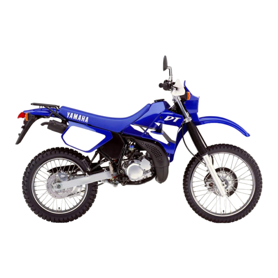
EAU00026 DESCRIPTION Left view 1. Headlight (page 6-33) 7. Starter (choke) (page 3-10) 2. Radiator cap (page 6-13) 8. Shift pedal (page 3-5, 5-4) 3. Fuel cock (page 3-9) 9. Y.E.I.S. (page 3-14) 4. Air filter (page 6-15) 10. Y.P.V.S. (page 3-15) 5. -
Page 12: Right View
DESCRIPTION Right view 11. Tool kit (page 6-1) 12. Fuse (page 6-33) 13. Engine oil tank (page 3-9) 14. Rear brake pedal (page 3-6, 6-22) 15. Rear shock absorber spring preload adjusting nut (page 3-13) -
Page 13: Controls/Instruments
DESCRIPTION Controls/Instruments 16. Clutch lever (page 3-5, 6-21) 21. Right handlebar switches (page 3-5) 17. Left handlebar switches (page 3-4) 22. Front brake lever (page 3-6, 6-27) 18. Speedometer (page 3-3) 23. Throttle grip (page 6-17, 6-27) 19. Coolant temperature gauge (page 3-4) 24. -
Page 14: Instrument And Control Functions
EAU00027 INSTRUMENT AND CONTROL FUNCTIONS EAU00063 High beam indicator light “&” This indicator comes on when the headlight high beam is used. 1 2 3 EAU01313 Oil level indicator light “ ” This indicator comes on when the oil level is low. This light circuit can be checked by the procedure on page 3- 1. -
Page 15: Oil Level Indicator Circuit Check
Shift into gear. Oil level indicator light Oil level indicator light does not come on. comes on. Engine oil level and Supply engine oil. Ask a Yamaha dealer to electrical circuit are OK. inspect electrical circuit. Go ahead with riding. -
Page 16: Speedometer
INSTRUMENT AND CONTROL FUNCTIONS NOTE: (for German model equipped with speed limiter only) This motorcycle is equipped with a speed limiter which prevents it from exceeding speed 80 km/h. 1. Speedometer 1. Tachometer 2. Odometer 2. Red zone 3. Trip odometer EAU00102 4. -
Page 17: Handlebar Switches
INSTRUMENT AND CONTROL FUNCTIONS EAU00127 Turn signal switch To signal a right-hand turn, push the switch to “6”. To signal a left-hand turn, push the switch to “4”. Once the switch is released it will return to the center position. To cancel the sig- nal, push the switch in after it has returned to the center position. -
Page 18: Clutch Lever
INSTRUMENT AND CONTROL FUNCTIONS 1. Engine stop switch 1. Clutch lever 1. Shift pedal N. Neutral EAU00138 EAU00155 Clutch lever Engine stop switch EAU00157 Shift pedal The engine stop switch is a safety The clutch lever is located on the left This motorcycle is equipped with a device for use in an emergency such handlebar. -
Page 19: Front Brake Lever
INSTRUMENT AND CONTROL FUNCTIONS 1. Front brake lever 1. Rear brake pedal 1. Fuel tank cap 2. Unlock EAU00158 EAU00162 3. Open Front brake lever Rear brake pedal EAU00177 The front brake lever is located on The rear brake pedal is on the right Fuel tank cap the right handlebar. -
Page 20: Fuel (Except For Switzerland And Austria)
INSTRUMENT AND CONTROL FUNCTIONS NOTE: The tank cap cannot be reinstalled unless it is unlocked. The key must remain in the cap until the cap is properly installed and locked onto the fuel tank. EW000023 1. Filler tube 1. Filler tube sure properly 2. -
Page 21: Catalyzer (For Switzerland And Austria)
INSTRUMENT AND CONTROL FUNCTIONS EW000130 EAU00191 EAU01084 Catalyzer Recommended fuel: (for Switzerland and Austria) Do not overfill the fuel tank. Avoid Regular unleaded gasoline This motorcycle is equipped with a spilling fuel on the hot engine. Do with a research octane catalytic converter in the exhaust not fill the fuel tank above the bot- number of 91 or higher. -
Page 22: Two-Stroke Engine Oil
INSTRUMENT AND CONTROL FUNCTIONS EC000114 OFF: closed position The following must be observed to prevent a fire hazard or other dam- ages. 8 8 Use only unleaded gasoline. FUEL Use of leaded gasoline will cause unrepairable damage to the catalytic converter. 1. -
Page 23: Starter (Choke) "1
INSTRUMENT AND CONTROL FUNCTIONS ON: normal position RES: reserve position FUEL FUEL 1. Arrow mark positioned “ON” 1. Starter (choke) “1” 1. Arrow mark positioned “RES” EAU02976 Starter (choke) “1” With the lever in this position, fuel This indicates reserve. If you run out Starting a cold engine requires a rich- flows to the carburetor. -
Page 24: Kick Starter
INSTRUMENT AND CONTROL FUNCTIONS To unlock the steering Insert the key, push it in and turn it 1/8 turn counterclockwise so that it moves out. Then, release remove the key. 1. Kick starter 1. Steering lock EAU00212 EAU02934 Kick starter Steering lock Rotate the kick starter away from the To lock the steering... -
Page 25: Seat
INSTRUMENT AND CONTROL FUNCTIONS 1. Bolt ( 1. Open EAU01648 EAU00261 To install Seat Helmet holder 1. Insert the projections on the front To remove To open the helmet holder, insert the of the seat into the holders, then 1. Remove panels D and E. (See key in the lock and turn it as shown. -
Page 26: Rear Shock Absorber Adjustment
INSTRUMENT AND CONTROL FUNCTIONS 3. Tighten the locknut to the speci- fied torque. “A” Tightening torque: Locknut: 55 Nm (5.5 m0kg) EC000018 Always tighten the locknut against 1. Locknut 2. Adjusting nut the spring adjusting nut and tight- EAU01650 Spring preload: en the locknut to the specified Rear shock absorber Minimum (soft):... -
Page 27: Rear Carrier
Cylinder damage will result in poor EC000022 damping performance. 8 8 Take your shock absorber to a Never attempt modify Yamaha Energy Induction System. Yamaha dealer for any service. 3-14... -
Page 28: Y.p.v.s
Adjustment should be EC000024 left to a Yamaha dealer who has the professional knowledge and experi- If the Y.P.V.S. does not operate, ence to do so. ask a Yamaha dealer to inspect the vehicle. -
Page 29: Sidestand Switch Operation Check
ENGINE WILL START. of a malfunction, return the motor- cycle to a Yamaha dealer immedi- PULL IN THE CLUTCH LEVER AND ately for repair. PUT TRANSMISSION IN GEAR. 3-16... -
Page 30: Pre-Operation Checks
EAU01114 PRE-OPERATION CHECKS Owners are personally responsible for their vehicle’s condition. Your motorcycle’s vital functions can start to deteriorate quickly and unexpectedly, even if it remains unused (for instance, if it is exposed to the elements). Any damage, fluid leak or loss of tire pressure could have serious consequences. Therefore, it is very important that, in addition to a thor- ough visual inspection, you check the following points before each ride. - Page 31 PRE-OPERATION CHECKS ITEM CHECKS PAGE 9 Check for smooth operation. Brake and shift pedal shafts 9 Lubricate if necessary. 6-28 9 Check for smooth operation. Brake and clutch lever pivots 9 Lubricate if necessary. 9 Check for smooth operation. Sidestand pivot 6-29 9 Lubricate if necessary.
-
Page 32: Operation And Important Riding Points
Consult of the following conditions: Yamaha dealer regarding any 8 The transmission is in neutral. control or function that you do 8 The sidestand is up, the trans- not thoroughly understand. - Page 33 OPERATION AND IMPORTANT RIDING POINTS TURN THE MAIN SWITCH TO "ON" AND THE ENGINE STOP SWITCH TO “#”. IF TRANSMISSION IS IN NEUTRAL IF TRANSMISSION IS IN GEAR AND SIDESTAND IS DOWN, AND SIDESTAND IS UP, APPLY THE CLUTCH LEVER AND KICK KICK THE KICK STARTER.
-
Page 34: Starting A Warm Engine
The engine is warm when it responds on. If the light does not come on, ask normally to the throttle with the starter a Yamaha dealer to inspect it. (choke) turned off. 4. Turn on the starter (choke) and completely close the throttle grip. -
Page 35: Shifting
OPERATION AND IMPORTANT RIDING POINTS EC000048 EAU02937 Recommended shift points (for Switzerland only) 8 8 Do not coast for long periods The recommended shift points are with the engine off, and do not shown in the table below. tow the motorcycle a long dis- tance. -
Page 36: Tips For Reducing Fuel Consumption
OPERATION AND IMPORTANT RIDING POINTS EAU00424 EAU00436 EAU00453 Tips for reducing fuel Engine break-in 0 ~ 500 km consumption There is never a more important peri- Avoid operation above 6,000 r/min. Your motorcycle’s fuel consumption od in the life of your motorcycle than Stop the engine and let it cool for 5 to depends to a large extent on your rid- the period between zero and 1,000... -
Page 37: Parking
EW000058 8 8 If any engine trouble should occur during the break-in peri- The exhaust system is hot. Park od, consult a Yamaha dealer the motorcycle in a place where immediately. pedestrians or children are not likely to touch the motorcycle. Do not park the motorcycle on a slope or soft ground;... -
Page 38: Periodic Maintenance And Minor Repair
Safety is an obligation done by a Yamaha dealer. of the motorcycle owner. The mainte- nance and lubrication schedule chart should be considered strictly as a guide to general maintenance and lubrication intervals. -
Page 39: Periodic Maintenance And Minor Repair
PERIODIC MAINTENANCE AND MINOR REPAIR NOTE: If you do not have necessary tools required during a service operation, take your motorcycle to a Yamaha dealer for service. EW000063 Modifications to this motorcycle not approved by Yamaha may cause loss of performance, and render it unsafe for use. -
Page 40: Periodic Maintenance And Lubrication Chart
8 The annual checks must be performed every year, except if a kilometer-based maintenance is performed instead. 8 From 30,000 km, repeat the maintenance intervals starting from 6,000 km. 8 Items marked with an asterisk should be performed by a Yamaha dealer as they require special tools, data and technical skills. - Page 41 PERIODIC MAINTENANCE AND MINOR REPAIR ODOMETER READING ( 1,000 km) ANNUAL ITEM CHECK OR MAINTENANCE JOB CHECK • Check runout, spoke tightness and for damage. Wheels • Tighten spokes if necessary. • Check tread depth and for damage. • Replace if necessary. Tires •...
- Page 42 PERIODIC MAINTENANCE AND MINOR REPAIR ODOMETER READING ( 1,000 km) ANNUAL ITEM CHECK OR MAINTENANCE JOB CHECK • Check starter (choke) operation. Carburetor • Adjust engine idling speed. • Check operation. Autolube pump • Bleed if necessary. • Check oil level. Transmission oil •...
-
Page 43: Cowling Removal And Installation
PERIODIC MAINTENANCE AND MINOR REPAIR 1. Cowling A 1. Cowling C 1. Screw ( 2) 2. Cowling B EAU01534* Cowling A EAU01065 Cowling removal and To remove installation Remove the screws and pull outward The cowlings indicated in the illustra- as shown. -
Page 44: Cowling B
PERIODIC MAINTENANCE AND MINOR REPAIR 1. Screw ( 3) EAU01534* To install To install Cowling B Place in the original position and Place in the original position and To remove install the screws. install the screws. Remove the screws and pull outward as shown. -
Page 45: Cowling C
PERIODIC MAINTENANCE AND MINOR REPAIR 1. Screw ( 3) 1. Panel D EAU01534* EAU01122 To install Cowling C Panel removal and Place in the original position and installation To remove install the screws. Remove the screws and pull outward The panels illustrated need to be as shown. -
Page 46: Panel D
PERIODIC MAINTENANCE AND MINOR REPAIR 1. Panel E 1. Screw 1. Screw EAU01535* EAU01535* Refer to this section each time a Panel D Panel E panel has to be removed or rein- To remove To remove stalled. Remove the screw and pull outward Remove the screw and pull outward as shown. -
Page 47: Spark Plug
Do not attempt to diagnose such Spark plug tool kit to remove the spark plug problems yourself. Instead, take the Removal as shown. motorcycle to a Yamaha dealer. You 1. Remove the spark plug cap. should periodically remove inspect the spark plug because heat and deposits will cause any spark plug to slowly break down and erode. -
Page 48: Transmission Oil
PERIODIC MAINTENANCE AND MINOR REPAIR NOTE: If a torque wrench is not available when you are installing a spark plug, a good estimate of the correct torque is 1/4 to 1/2 turn past finger tight. Have the spark plug tightened to the specified torque as soon as possible. - Page 49 PERIODIC MAINTENANCE AND MINOR REPAIR 5. Fill the engine with sufficient oil to reach the specified level. Install the oil filler cap and tight- en it. Recommended oil: See page 8-1. Oil quantity: Total amount: 0.8 L 1. Oil filler cap 1.
-
Page 50: Cooling System
EAU01808 EAU03101 Cooling system Changing the coolant NOTE: If water is added, have a Yamaha 1. Remove panel D. (See page 6-9 1. Put the motorcycle on a level dealer check the antifreeze content of place. for panel removal and installation the coolant as soon as possible. - Page 51 PERIODIC MAINTENANCE AND MINOR REPAIR 8. Install the reservoir tank hose. 9. Pour the recommended coolant into the radiator until it is full. Recommended antifreeze: High quality ethylene glycol antifreeze containing corrosion inhibitors for aluminum engines. 1. Drain bolt 1. Reservoir tank hose Antifreeze and water mixing ratio: 2.
-
Page 52: Air Filter
14. Install the reservoir tank cap and procedures.) check for coolant leakage. 2. Remove the air filter case by NOTE: removing the screws. If any leakage is found, ask a Yamaha dealer to inspect the cooling system. 15. Install the cowling and the panel. 6-15... -
Page 53: Carburetor Adjustment
Most adjustments screws. should be left to a Yamaha dealer who has the professional knowledge EC000082 and experience to do so. However, the following may be serviced by the 8 8 Make sure the air filter is prop- owner as part of routine mainte- 1. -
Page 54: Idle Speed Adjustment
PERIODIC MAINTENANCE AND MINOR REPAIR Standard idle speed: 1,250 ~ 1,450 r/min NOTE: If the specified idle speed cannot be obtained by performing the above adjustment, consult a Yamaha deal- 1. Throttle stop screw a. Free play EAU00632 EAU00634 Idle speed adjustment... -
Page 55: Tires
PERIODIC MAINTENANCE AND MINOR REPAIR EAU00652 180 kg Tires Maximum load* 178 kg (CH, A only) To ensure maximum performance, Cold tire pressure Front Rear long service and safe operation, note 125 kPa 150 kPa the following: Up to 90 kg (1.25 kg/cm , (1.50 kg/cm 1.25 bar) - Page 56 Yamaha Motor Co., handling, braking, performance Ltd. for this model. No guarantee and safety. Do not carry loosely for handling characteristics can be...
-
Page 57: Wheels
If any abnormal related wheel parts replace- condition exists in a wheel, con- ment should be left to a sult a Yamaha dealer. Do not Yamaha Service Technician. attempt even small repairs to the 8 8 Patching a punctured tube is wheel. -
Page 58: Clutch Lever Free Play Adjustment
PERIODIC MAINTENANCE AND MINOR REPAIR 1. Locknut 1. Locknut 1. Locknut 2. Adjusting bolt 2. Adjusting nut 2. Adjusting bolt 3. Free play 3. Free play 4. Loosen the locknut at the clutch EAU00694 EAU00696 Clutch lever free play lever. Front brake lever free play adjustment 5. -
Page 59: Rear Brake Pedal Height Adjustment
15 mm below the top of result in loss of control and an the footrest. If not, ask a Yamaha accident. Have a Yamaha deal- dealer to adjust it. er inspect and bleed the sys- tem if necessary. -
Page 60: Brake Light Switch Adjustment
The rear brake light switch is activat- and wear. If the thickness is less than ed by the brake pedal and is properly the specified value, have a Yamaha adjusted when the brake light comes dealer replace the pads. on just before braking takes effect. -
Page 61: Inspecting The Brake Fluid Level
Insufficient brake fluid may let air ing leakage and poor brake per- 8 Have a Yamaha dealer check enter the brake system, possibly formance. the cause if the brake fluid level causing the brakes to become inef- goes down. -
Page 62: Brake Fluid Replacement
The brake fluid should be replaced both wheels on the ground and with- only by trained Yamaha service per- out rider. Check the slack at the posi- sonnel. Have the Yamaha dealer tion shown in the illustration. Normal replace the following components slack is approximately 25 ~ 40 mm. -
Page 63: Drive Chain Slack Adjustment
PERIODIC MAINTENANCE AND MINOR REPAIR EC000096 EAU03006 Drive chain lubrication The chain consists of many parts Too little chain slack will overload which work with each other. If the the engine and other vital parts. chain is not maintained properly, it Keep the slack within the specified will wear out quickly. -
Page 64: Cable Inspection And Lubrication
Lubricate the cables and cable ends. purpose grease. If a cable does not operate smoothly, ask a Yamaha dealer to replace it. Recommended lubricant: Engine oil 6-27... -
Page 65: Autolube Pump Adjustment
Lubricate the pivoting parts. Lubricate the pivoting parts. cated adjustment. Recommended lubricant: Recommended lubricant: Adjusting should be left to a Yamaha Engine oil Engine oil dealer who has the professional knowledge and experience to do so. 6-28... -
Page 66: Sidestand Lubrication
Operation check If the sidestand does not move age from the front fork. 1. Place the motorcycle on a level smoothly, consult a Yamaha deal- place. 2. Hold the motorcycle in an upright position and apply the front brake. -
Page 67: Steering Inspection
Hold the lower end of the front forks and try to move them forward and backward. If any free play can be felt, ask a Yamaha dealer to inspect and adjust the steering. Inspection is eas- ier if the front wheel is removed. -
Page 68: Battery
PERIODIC MAINTENANCE AND MINOR REPAIR EC000099 EW000116 When inspecting the battery, be Battery electrolyte is poisonous sure the breather hose is routed and dangerous, causing severe correctly. If the breather hose is burns, etc. It contains sulfuric positioned in such a way as to acid. - Page 69 PERIODIC MAINTENANCE AND MINOR REPAIR EC000100 Battery storage 8 When the motorcycle will not be Normal tap water contains miner- used for a month or longer, als which are harmful to a battery; remove the battery, fully charge therefore, refill only with distilled it and store it in a cool, dry place.
-
Page 70: Fuse Replacement
Turn on the switches 6-6 ~ 6-7 for removal and instal- and see if the electrical device oper- lation procedures.) ates. If the fuse immediately blows 2. Remove the headlight unit by again, consult a Yamaha dealer. removing the bolts. 6-33... - Page 71 6. Install the bulb holder cover, con- nector and headlight unit. 7. Install the cowling. 8. If the headlight beam adjustment is necessary, ask a Yamaha dealer to make that adjustment. 1. Bulb holder cover 1. Bulb holder 2. Connector 4.
-
Page 72: Turn Signal Light Bulb Replacement
PERIODIC MAINTENANCE AND MINOR REPAIR EC000108 Do not over-tighten the screws as the lens may break. 1. Screw 1. Screw ( 2) 2. Lens 2. Lens 3. Bulb 3. Bulb EAU01095 EAU01623* Turn signal light bulb Tail/brake light bulb replacement replacement 1. -
Page 73: Supporting The Motorcycle
PERIODIC MAINTENANCE AND MINOR REPAIR EAU01579 Rear wheel service Supporting the motorcycle Use a motorcycle stand or motorcycle Since the Yamaha DT125R has no jack to elevate the motorcycle so the centerstand, follow these precautions rear wheel ground. when removing the front and rear... -
Page 74: Front Wheel Installation
PERIODIC MAINTENANCE AND MINOR REPAIR 1. Speedometer cable 2. Axle holder nut ( 4) EAU03104 3. Make sure the slot in the 3. Wheel axle Front wheel installation speedometer gear unit fits over 3. Elevate the front wheel by plac- 1. -
Page 75: Rear Wheel Removal
8 8 It is advisable to have a 6. Pull out the rear axle and remove in this sequence, there should be the wheel assembly by pulling Yamaha dealer service the a gap formed at the bottom of backward. wheel. -
Page 76: Rear Wheel Installation
If your motorcycle requires any side outward. repair, bring it to a Yamaha dealer. 3. Install the swingarm end bolts. The skilled technicians at a Yamaha 4. Adjust the drive chain. dealership have the tools, experi- 5. -
Page 77: Troubleshooting Chart
Open throttle half-way and start Wipe clean with dry cloth and correct Wet. spark gap or replace spark plug. the engine. Remove spark plug and check electrodes. Engine doesn’t start, ask a Yamaha Dry. Ask a Yamaha dealer to inspect. dealer to inspect. 6-40... -
Page 78: Engine Overheating
Restart the engine. If the engine overheats again, ask a Level is OK. Yamaha dealer to inspect and repair the cooling system. NOTE: If it is difficult to get the recommended coolant, tap water can be temporarily used, provided that it is changed to the rec- ommended coolant as soon as possible. -
Page 79: Motorcycle Care And Storage
EAU01518 MOTORCYCLE CARE AND STORAGE Before cleaning Cleaning Care 1. Cover up the muffler outlet with a After normal use exposure technology plastic bag. Remove dirt with warm water, a neu- makes a motorcycle charming but 2. Make sure that all caps and cov- tral detergent and a soft clean also vulnerable. - Page 80 MOTORCYCLE CARE AND STORAGE 8 8 Improper cleaning can damage 8 8 Do high-pressure After riding in the rain, near the sea windshields, cowlings, panels washers or steam-jet cleaners or on salt-sprayed roads and other plastic parts. Use since they cause water seep- Since sea salt or salt sprayed on the only a soft, clean cloth or age and deterioration in the...
- Page 81 After cleaning NOTE: 1. Dry motorcycle with Consult a Yamaha dealer for advice Make sure that there is no oil or chamois or an absorbing cloth. on what products to use. wax on the brakes and tires. If nec- 2. Immediately dry the drive chain...
-
Page 82: Storage
MOTORCYCLE CARE AND STORAGE Long-term a. Remove the spark plug cap and Storage Before storing your motorcycle for spark plug. Short-term several months: b. Pour a teaspoonful of engine oil Always store your motorcycle in a 1. Follow all the instructions in the into the spark plug bore. - Page 83 MOTORCYCLE CARE AND STORAGE 6. Lubricate all control cables and 9. Remove the battery and fully the pivoting points of all levers charge it. Store it in a cool, dry and pedals as well as of the place and recharge it once a sidestand/centerstand.
-
Page 84: Specifications
EAU01038 SPECIFICATIONS Specifications Model DT125R Compression ratio 6.7:1 Dimensions Starting system Kick starter Overall length 2,170 mm Lubrication system Separate lubrication 2,235 mm (N, S, SF, CH, A only) (Yamaha autolube) Overall width 830 mm Engine oil (2-cycle) Overall height... - Page 85 SPECIFICATIONS Carburetor Chassis Type quantity TM28SS Frame type Semi double cradle Manufacturer MIKUNI Caster angle 27°30’ Spark plug Trail 113 mm Manufacturer / type NGK / BR9ES Tire NGK / BR8ES (CH, A only) Type With tube Spark plug gap 0.7 ~ 0.8 mm Front Clutch type...
- Page 86 SPECIFICATIONS 90 kg load ~ maximum Rear load* Type Single disc brake Front 150 kPa (1.50 kg/cm , 1.50 bar) Operation Right foot operation Rear 175 kPa (1.75 kg/cm , 1.75 bar) Fluid DOT 3 or DOT 4 Off-road riding Suspension Front 125 kPa (1.25 kg/cm...
- Page 87 SPECIFICATIONS Battery Type GM3-3B Voltage, capacity 12 V, 3 AH Headlight type Conventional incandescent bulb Bulb voltage, wattage quantity Headlight 12 V, 45/40 W Tail / Brake light 12 V, 5/21 W Front flasher light 12 V, 21 W Rear flasher light 12 V, 21 W Auxiliary light 12 V, 4 W...
-
Page 88: How To Use The Conversion Table
SPECIFICATIONS EAU01064 HOW TO USE THE CONVERSION TABLE CONVERSION TABLE All specification data in this manual are listed in SI and METRIC TO IMPERIAL METRIC UNITS. Metric unit Multiplier Imperial unit Use this table to convert METRIC unit data to m •... -
Page 89: Consumer Information
Record the key identification number, vehicle identification number and model label information in the spaces provided for assistance when order- ing spare parts from a Yamaha deal- er or for reference in case the vehicle is stolen. 1. Key identification number 1. -
Page 90: Model Label
1. Model label EAU01049 Model label The model label is affixed to the loca- tion shown in the figure. Record the information on this label in the space provided. This information will be needed to order spare parts from your Yamaha dealer. - Page 91 YAMAHA MOTOR CO., LTD. PRINTED ON RECYCLED PAPER PRINTED IN JAPAN 2000·12–0.4 1(E)
Need help?
Do you have a question about the DT125R and is the answer not in the manual?
Questions and answers