Table of Contents
Advertisement
Quick Links
Advertisement
Table of Contents

Related Manuals for Avio IP-02UE


Summary of Contents for Avio IP-02UE
- Page 1 A Proposal for New Presentations Intelligent Projector User’s Manual iP - 02UE...
-
Page 2: About Trademarks
This is a Class A product. In a domestic environment this product may cause radio interference in which case the user may be required to take adequate measures. Thank you for your purchase of an AVIO product. Please read this manual carefully in order to use the projector properly. -
Page 3: Safety Precautions
Safety Precautions WARNING • Concerning the use of this projector: • It is anticipated that this projector will be used by adults. Especially when children younger than junior high school stu- dents will be using this projector, we ask that an adult always attend the use of the projector for safety. • If a fault occurs: • If you detect smoke, or a strange smell or sound, immediately disconnect the power cable. It is dangerous to continue using the projector after a fault occurs. Return the projector to the dealer where it was pur- chased for repair. - Page 4 Safety Precautions • Do not turn on the light of the projector unless the projector is installed horizontally • Do not turn on the light of the projector when the projector is oriented other than horizontally: up side down, facing up, on its side, or facing down. Doing so may cause a fire or lamp explosion. Warning Please check the rating of the power cable. Prior to using a power cable, please make sure that the cable is fully compliant with the power ratings and the type of the plug in the area and, if not, purchase proper power cable for the area.
- Page 5 Safety Precautions • Dew condensation • Abruptly moving the unit to a place where there is a great temperature difference causes dew condensation on the main unit. Projection under a dew condensed state causes a failure. • Servicing and cleaning • Have the internal components cleaned by a retailer about once a year. There is a risk of fire or faulty operation if the in- side of the projector gets dusty and is not cleaned for a long time. For best results, the projector should be serviced be- fore the wet season brings damp conditions.
- Page 6 Safety Precautions • Do not do the followings • Do not put anything heavy on the projector. • Do not step on the projector, rack, or stand. Do not hold or hang on the projector. Doing so could cause the projector to roll over or break, resulting in injury. Especially be careful if small children are near. • Do not use the rack unless the casters are locked when placing the projector on a rack with casters. Doing so may cause the projector to move or roll over, resulting in injury. • Do not turn the lamp on/off within one minute after it is turned off/on. Extremely high voltage is generated in the lamp just after it is turned on.
-
Page 7: Table Of Contents
Table of Contents Safety Precautions ............... E-3 Table of Contents ..............E-7 A Check of the Supplied Items and the Names of the Parts . E-9 Supplied Parts Check ...................... E-9 Names and Functions of the Parts (Projector) .............. E-10 Names and Functions of the Parts (Input Connectors) .......... -
Page 8: Table Of Contents
Table of Contents Menu Configuration ............E-34 Menu Operation Method ............. E-35 Names and Functions of the Buttons Used in Menu Operation ........E-35 Names and Functions of the Menu Parts ..............E-35 Method of Menu Operation ................... E-36 Menu Description ............... E-38 Pointer •... -
Page 9: A Check Of The Supplied Items And The Names Of The Parts
A Check of the Supplied Items and the Names of the Parts Supplied Parts Check Please check that the supplied parts are included. Pull out the sheet before use. Remote control Coin-type lithium battery: CR2025 Projector (Inside the remote control) (main unit) Lens cap Power cable (3 m) PC connection cable (2 m) User’s Manual... -
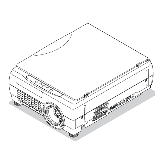
Page 10: Names And Functions Of The Parts (Projector
A Check of the Supplied Items and the Names of the Parts Names and Functions of the Parts (Projector) Air intake Air is drawn in from the side. Focus adjustment ring Turn this to adjust the focus. See Page E-24. Document cover The document or printed material to be read is Input connector panel placed under this cover. - Page 11 A Check of the Supplied Items and the Names of the Parts Document reading area The document or printed mate- rial that you wish to project in the OHP mode is placed here. See Page E-33. Remote control IR sensor Speaker (monaural) Handle Air intake Air is drawn in from here.
-
Page 12: Names And Functions Of The Parts (Input Connectors
A Check of the Supplied Items and the Names of the Parts Names and Functions of the Parts (Input Connectors) 1. Computer/video (D terminal output) video input con- 3. PC/VIDEO audio input jack nector This is the audio input jack for PC/Video. (Stereo is sup- Use this input terminal for connection to a computer’s ana- ported) log RGB input connector or a video deck’s D connector... -
Page 13: Names And Functions Of The Parts (Operation Panel
A Check of the Supplied Items and the Names of the Parts Names and Functions of the Parts (Operation Panel) INPUT PORTRAIT FREEZE OFF FREEZE /CAPTURE ON/STANDBY LAMP/COVER TEMP 1. ON/STANDBY LED 4. ON/STANDBY Button Lit red during standby and lit green when the projection Switches the power of the projector on or off (standby lamp is on. -
Page 14: Names And Functions Of The Parts (Remote Control
A Check of the Supplied Items and the Names of the Parts Names and Functions of the Parts (Remote Control) 6. MENU Button Switches on or off the display of the menu screen. See Page E-35. 7. SCROLL Buttons Sets the selection of the item or the adjustment value at the menu screen. -
Page 15: Operation Of The Remote Control
A Check of the Supplied Items and the Names of the Parts Operation of the Remote Control • Please use the remote control within a range of about 7 m from the remote control IR sensor of the projector (located at both the front and rear) and within an angle of 10 degrees to the left and 10 degrees to the right. Note that this distance may be shorter depending on battery consumption. -
Page 16: Procedure Up To Projection
Adjust the image to provide the optimum condition, as required. → See Page E-42 - E-43 NOTE While AVIO conducts strict quality inspections, with DLP type projectors, in some rare cases there may be black spots or bright ® spots within the pixels. Please note that this is not a malfunction. -
Page 17: Projection Distance And Screen Size
Projection Distance and Screen Size Please use the following diagrams to determine the screen display size and the type of screen required for any given projector location. Projection distances that will be in focus will be 1.30 m (4.27 feet) to 10.96 m (35.96 feet) from the front of the lens. Please arrange the setup within this range. -
Page 18: Connections With The Personal Computer
Connections with the Personal Computer Connection Precautions • To protect this projector and the equipment to be connected, switch off the power of each unit before making connections. • Please read the various equipment instruction manuals for information about the connection of the equipment and the method of use. • When connection is made with a notebook computer and the image is displayed on the LCD screen of the notebook computer, a proper display might not be obtained on projection screen. Switching off CAUTION the display of the notebook computer will result in a proper display. -
Page 19: Personal Computer Input Connector
Connections with the Personal Computer Connecting Macintosh Computers • When the monitor output is set to the VGA port (mini D-SUB 15-pin), mount the PC connection cable included with the main unit. • An optional Apple video adapter cable is required when the monitor output is a video port or DVI port. Personal Computer Input Connector Personal Computer Input Connector The personal computer input connector uses a 15-pin mini D-SUB type connector. The pins and their corresponding signal inputs are described below. ①... -
Page 20: When The Image Of The Personal Computer Screen Is Not Projected
Connections with the Personal Computer When the Image of the Personal Computer Screen Is Not Projected Please check the matters described below when the image of the personal computer is not projected or when there is projection but the image is not correct. ●... -
Page 21: Table Of Supported Input Signals
Connections with the Personal Computer Table of Supported Input Signals Signals indicated with a “Yes” are supported. Note that depending on the model of personal computer, please per- form the screen adjustment of the “Image adjustment” → “Sync adjustment” menu if flickering or bleeding appear on the projection screen. → See Page E-40 Resolution Horizontal Frequen- Vertical Frequency... -
Page 22: Connections With Video Equipment
Connections with Video Equipment The video of a video tape deck or DVD player is projected onto a large screen. iP-02 Projector side connector panel D terminal/ RGB conversion cable RCA cable (commercially available) (Option: Model name IPC-D/VGA) To the video output To the audio out- connector put connectors Video deck DVD player NOTE: • When a video signal have a lot of noise, the image may be displayed in monochrome. Should this occur, make a setting with the “Video select” menu to suit the input signal. • The lamp turns off if no signal is being input and no operation has been performed for over 15 minutes. -
Page 23: Connection Of The Power Cable And On/Off Switching
Connection of the Power Cable and On/Off Switching Switch On the Power Connect the power cable The projector will enter the standby mode and the ON/ STANDBY LED will light in red. INPUT ON/STANDBY LAMP/COVER TEMP To wall outlet. Press the ON/STADNBY button ( ) The fan will turn, the lamp will light, and the ON/STANDBY LED will light in Operation with the Operation with the green. -
Page 24: Adjustment Of The Projection Image
Adjustment of the Projection Image Adjusting the Projection Image Adjust the projection image to the screen. • When the image is shifted to the left or right, move the projector horizon- tally. (Align the center of the screen with the center of the projector lens.) • When the image is shifted up or down, use the tilt foot to adjust the pro- jector vertically. • When the image is slanted, turn the left or right tilt foot to adjust. Right angle • When there is distortion in the shape of a trapezoid, adjust with KEY- STONE of the menu operations. -
Page 25: Regular Operation
Regular Operation This section describes the use of direct operation using the projector and remote control buttons. Please see the items on Page E-36 “Method of Menu Operation” and Page E-38 “Menu Description” for information about operation using the menu. Select the Input When the projector’s power is turned on, one of the input selection icons ([OHP, PC or VIDEO] or [OHP, VIDEO (Component) or VIDEO]) is displayed. -
Page 26: Enlarging And Reducing The Projection Image
Regular Operation To view the portion that has been cut off Operation with the Projector Scrolling is not possible from the main unit’s control panel. Operation with the Remote Control Press the SCROLL (▲▼) buttons and scroll the projec- tion image up or down. • Pressing the ZOOM (−) button permits display of a large portion within the reading range of the vertical display. -
Page 27: Adjusting The Brightness
Regular Operation Moving the Screen Movement is possible in 4 directions (up, down, left, and right). Operation with the Projector Scrolling is not possible from the main unit’s control panel. Operation with the Remote Control Press the SCROLL (▲▼◀▶) buttons. Adjusting the Brightness To change the brightness, perform a manual adjustment using the method described below. Operation with the Projector The brightness cannot be adjusted from the main unit’s control panel. -
Page 28: Capturing The Projection Image / Still Image Display
Regular Operation Capturing the Projection Image / Still Image Display Effective Only with OHP Input At time of OHP input Operation with the Projector] INPUT PORTRAIT FREEZE OFF FREEZE /CAPTURE ON/STANDBY Press the still FREEZE/CAPTURE button. LAMP/COVER When the FREEZE/CAPTURE button is pressed, the OHP TEMP document is stored in the internal memory as an OHP his- tory image. -
Page 29: Making Presentations Using Images In The Internal Memory Or An A Usb Memory Stick
The display should return to normal. Prepare the material Insert a USB memory stick into the projector. Page E-12 • Using the iP-Viewer tool, images other than those captured with this projector can be converted, and they can be pro- jected with this projector. * The iP-Viewer tool can be downloaded free of charge from the Avio website. http://www.avio.co.jp/support/mp/index.htm Open the folder list Operation at the main INPUT... - Page 30 Regular Operation Choosing a folder Operation with the Remote Control Press the remote control’s scroll ▲▼◀▶ buttons to set the folder cursor to the folder image you want to project. When the number of the folder images exceeds 16, pressing the scroll button changes over to the other page. Open the file list Operation with the Press the remote control’s SET/POINTER button to open the...
-
Page 31: Stick
Regular Operation Projection on the full screen Operation with the Remote Control Press the SET/POINTER button of the remote control. The reduced image at the cursor position is projected on the full projec- tion screen of the projector. Onscreen operation When feeding a page, choose the menu “Next.” The operation can also be changed with the VOLUME + and VOLUME −... -
Page 32: Displaying The Pointer
Regular Operation Displaying the Pointer This operation displays the pointer in the currently projected image. Operation with the Projector The ability to turn on and turn off the pointer is not available from the operation panel of the projector. Operation with the Remote Control Press the SET/POINTER button. One more press of the SET/POINTER button while the pointer is displayed will turn off the pointer display. -
Page 33: Method Of Ohp Operation
Method of OHP Operation Attaching the Document Cover The mounting orientation of the document cover can be changed to the opposite direction in accordance with the circum- stances circumstances. NOTE: When removing the document cover, lift the cover by both hands and remove it. -
Page 34: Menu Configuration
Menu Configuration The adjustment/setting items and content will differ depending on the input selection and the permitted information will be displayed on the menu for that input mode. Pointer•Screen Image adjustment Settings Pointer • Screen Image adjustment Settings Pointer • Screen History menu Back page in history Next page in history Pointer shape Keystone... -
Page 35: Menu Operation Method
Menu Operation Method Names and Functions of the Buttons Used in Menu Operation SCROLL ▲▼◀▶ Buttons Used in the selection of menu names and item names, and to set and adjust item contents. SET/POINTER Button Used to finalize a setting after making the setting or adjustment. MENU Button Used to display a menu and to close a menu. -
Page 36: Method Of Menu Operation
Menu Operation Method Method of Menu Operation This section describes the actual operation method. Adjustment of [Brightness] using the remote control is provided as an example. Press the MENU button and display the menu Select [Image adjustment] with the SCROLL ◀▶ buttons Each press of the SCROLL ▶ button switches the menu one step in the sequence of [Pointer • Screen] → [Image adjustment] → [Settings], and each press of the SCROLL ◀ button causes a return in the opposite direction. Display the detailed menu with the SCROLL ▼ button or the SET/POINTER button, then select [Brightness]. - Page 37 Menu Operation Method Make the adjustment with the SCROLL ◀▶ buttons while checking the projection im- SCROLL ◀ button: Each press causes the numerical value to decrease. SCROLL ▶ button: Each press causes the numerical value to increase. Press the MENU button and close the menu This completes the [Brightness] adjustment. E-37...
-
Page 38: Menu Description
Menu Description Pointer • Screen This selects the shape, color, and size of the pointer. During OHP input Pointer shape ....Selects the shape of the pointer from 2 types. Pointer color ....Selects the color of the pointer from amongst 3 types (i.e., red, white, and blue). -
Page 39: History Menu
Menu Description History menu OHP input only No. sheets on thumbnail display When a list of history images is displayed ..........Select the number of thumbnail images to be displayed simultane- ously on one screen. 4 sheets: Four thumbnail images are displayed at once. -
Page 40: Image Adjustment
Menu Description Image adjustment This performs the settings and adjustments related to the During OHP input projected image. When OHP input has been selected. Red (Red color adjustment) ..........Adjusts the deepness of the red color in the range of −50 to 50. ... - Page 41 Menu Description Sub menu: Sync adjustment Clock .......Adjusts the horizontal size of the projected image in the range of −50 to 50. Phase ......Adjusts the noise/flickering of the projected image in the range of −50 to 50. Horizontal ......Adjusts the horizontal position of the projected image in the range of −50 to 50.
-
Page 42: Settings
Menu Description Settings This performs settings related to the projector unit or while the projector is in use. Lamp usage time .....Displays the usage time of the lamp. “Replacement of the Lamp Unit” → See Page E-46 Input signal ......The name of the currently selected input is displayed. - Page 43 Menu Description NOTE: • When keystone correction has been applied, the resolution at the screen edges will degrade and small characters and the like will become difficult to see. When you do not wish to have the resolution degradation, set the projector on a level platform and set the numerical value of the Keystone menu to “0” (no correction). • Compared to when keystone correction is not applied, the application of keystone correction results in a display image (of characters, etc.) that appears somewhat blurred and this is related to the image processing that is performed.
-
Page 44: Maintenance
Maintenance Fault Protection The projector is equipped with a built-in protection circuit to prevent fire and breakdown due to faults. When the LAMP/COVER LED lights in red Measures to be taken 1. Disconnect the power plug from the outlet. 2. Properly install the lamp unit cover. See “Replacement of the Lamp Unit” on Page E-46. When the TEMP LED flashes or lights steadily ... - Page 45 Maintenance When the power has failed (When all the LED go off with the power ON) Measures to be taken 1. Disconnect the power plug from the outlet. 2. Check the following matters and perform the countermeasure properly. Is the ambient temperature in Please use the projector in an operation ambient temperature excess of 35°C (95°F)? of 5°C (41°F) to 35°C (95°F).
-
Page 46: Replacement Of The Lamp Unit
Maintenance Replacement of the Lamp Unit The projection lamp used on this projector should be replaced after about the number of hours indicated below (or sooner, depending on the usage conditions). When the usage time exceeds 2000 hours*, the possibility for explosion increases, so the lamp is forcibly shut off. When the usage time exceeds 1900 hou rs, replace the lamp unit (sold separately) before the usage time reaches 2000 hours. -
Page 47: Lamp Unit Replacement Procedure
Maintenance Lamp Unit Replacement Procedure To prevent burns, wait one hour or longer after the lamp has been switched off before performing the following proce- dure. Remove the lamp unit cover Using a flat-head screwdriver, loosen the lamp unit cov- er’s screw and pull the cover in the direction of the arrow to remove it. Loosen the mounting screws of the lamp unit Using a minus screwdriver, loosen the 2 screws of the lamp unit. - Page 48 Maintenance Reset the lamp usage time Please perform the operation indicated below in the standby mode (*). Operation with the Projector Press the INPUT, PORTRAIT, FREEZE OFF and FREEZE/CAPTURE buttons si- multaneously, then press the input selector and still picture buttons simultaneously. Operation with the Remote Control Resetting of the lamp usage time cannot be performed with the remote control. The LAMP/COVER LED will flash green following this and projection will start.
-
Page 49: Cleaning The Air Intake/Ventilation Slots
Maintenance Cleaning the Air Intake/Ventilation Slots The air intake/ventilation slots serve as the way in and out for the air that cools the internal heat of the projector. Depending on the flow of the air, dust may collect while you are using the projector. When dust collects, the internal temperature will rise and the rotation of the fan will also increase which will cause a drop in the life of the product or breakdown; therefore, please clean the projector regularly (on the order of once every month based on 4 hours of use per day). -
Page 50: Troubleshooting
T h e d a t a s t o r e d o n t h e U S B • Unplug the USB memory stick temporarily, then try reinserting it 2 or 3 seconds later. If there is no − memory stick cannot be viewed improvement, please check the USB memory stick. The remote control or the main • Unplug the power cord, wait 2 or 3 seconds, then plug the power cord back in. − unit’s key panel does not operate. NOTE: For the additional information, visit our web site (http://www.avio.co.jp) LED List LED State Significance ON/STANDBY LAMP/COVER TEMP AC power OFF Standby Standby to start of projection... -
Page 51: Repair Service
Repair Service Repair Service Procedure • During the warranty period, we will repair the product in accordance with the warranty regulations. Please request service at your store of purchase. Please submit the written warranty at the time of your request. • Please contact your store of purchase for repairs that follow the elapsed warranty period. When repair work enables the maintenance of product functions, charges will apply. for the repairs. • Before asking for repair service, check the Troubleshooting section on page E-50 once more. If this check confirms a problem, contact the dealer where you bought the product. -
Page 52: Specifications
*1 D terminal/RGB conversion cable is required for input of D1–D4 images *2 Avio optional USB memory sticks are guaranteed to operate. Other USB memory devices may not operate. Initial formatting of the USB memory using FAT 32 is required. Large number of recorded may delay the speed of saving/playback. - Page 53 E-53...
- Page 54 Zip code: 141-0031 Tel: +81-3-5436-0625 Fax: +81-3-5436-0639 Customer Support Center, Imaging and Information Products Division 4206 IKONOBE-CHO TSUZUKI-KU YOKOHAMA-SHI KANAGAWA, JAPAN Zip code: 224-0053 Tel: +81-45-930-3580 E-mail: support_ip@avio.co.jp URL: http://www.avio.co.jp To customers: E nter the name and date of the store where you purchased this prod- uct. This information will be useful when you ask your dealer for repair. • Date of Purchase (year, month, day) • Store of Purchase Telephone Number : ( )
Need help?
Do you have a question about the IP-02UE and is the answer not in the manual?
Questions and answers