Table of Contents
Advertisement
Advertisement
Table of Contents

Related Manuals for IROX PRO-X USB


Summary of Contents for IROX PRO-X USB
- Page 1 USER MANUAL PRO-X USB...
-
Page 2: Table Of Contents
Table of Contents Introduction Features Contents of Complete Weather Station Kit Installing your weather station Setting up the Remote Weather Sensors Setting up the UV Sensor Setting up the Thermo-Hygro Sensor(s) Setting up the Rain Sensor Setting up the Anemometer (wind sensor) Setting up the Main Console Unit Starting up the Main Console Unit Using your Weather Station... -
Page 3: Introduction
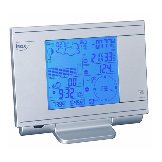
Introduction Congratulations on your purchase of the PRO-X USB Weather Station. The weather station consists of a main console unit with a remote control, as well as an assortment of remote sensors which collect and transmit a wide range of weather data, including outdoor temperature, humidity, wind speed and direction, rain amount and rain rate. - Page 4 Clock and Calendar (12hr/ 24 hr) (month/day or day/month) - Different combinations of clock and calendar displays - 6 languages for day of week (English/ German/ French/ Italian/ Spanish/ Dutch) Alarms - Single alarm: activated once at specified time - Weekday alarm: activated everyday from Monday to Friday at specified time - Pre-alarm: activated ahead of single or weekday alarm if channel 1 temperature falling to +2ºC or below.
-
Page 5: Contents Of Complete Weather Station Kit
Contents of Complete Weather Station Kit Before installing your weather station, please check that the following are complete: Hardware Fittings Komponenten Main Console Unit (optional) AC/DC Remote Control 7.5V output adaptor UV Sensor: - Sensor Unit - U-Shaped Sensor holder - Circular Base - Stake Base - Wall-Mounting... -
Page 6: Installing Your Weather Station
Anemometer 4 screws for (Wind Sensor): securing unit to - Wind Cups vertical surface - Wind Vane - Anemometer arm - Anemometer base 2m (6ft) USB cable Installing your weather station Setting up the Remote Weather Sensors Before starting up the main console unit, setup all the remote sensors first. When placing the sensors, make sure that they are within receiving range of the console unit. -
Page 7: Setting Up The Thermo-Hygro Sensor(S)
Placement tips: - The sensor should be mounted in an area free of shadows or reflections of sunlight by nearby coverings and objects. Setting up the Thermo-Hygro Sensor(s) 1. Open the latch at the base of the thermo-hygro sensor. 2. Set the channel with a slide switch. 3. -
Page 8: Setting Up The Anemometer (Wind Sensor)
Setting up the Anemometer (wind sensor) 1. Assemble the wind cups and wind vane to the anemometer arm 2. Attach the assembled anemometer to the base. 3. Insert two 2 x UM-3 or “AA” size 1.5V batteries into the battery holder in the base. 4. -
Page 9: Starting Up The Main Console Unit
Placement tips: Make sure that the console unit is within receiving range of all remote sensors. Ideally sensors should be within the line of sight of the console unit. Transmission range may be affected by trees, metal structures and electronic appliances. Test reception before permanently mounting your weather station. -
Page 10: Buttons And Controls
Buttons and Controls The infra-red remote control has buttons which correspond to the ones on the main unit. The following controls are available on both the main console unit and remote control: - Switches to next mode in anti-clockwise direction - Increment for setting parameters DOWN - Switches to next mode in clockwise direction... -
Page 11: Navigating Between Different Modes
The following controls are only available on the remote control: - Puts display in Temperature Mode Temperature Mode - Puts display in Wind Mode Wind Mode UV Mode - Puts display in UV Mode Pressure and Weather - Puts display in Pressure and Weather Forecast Mode Forecast Mode - Puts display in Rain Mode... - Page 12 Pressure and Weather Forecast Mode - Current pressure, trend, and history bar-chart - Weather forecast - Moon phase UV Mode - UV index Display or Minimal E - Daily Maximum Display - Weekly Maximum Display Clock and Alarm Mode - Radio Controlled clock showing current time and calendar - Single alarm, weekday alarm and pre-alarm Sunrise/Sunset Mode - Sunrise and sunset times...
- Page 13 Temperature and Humidity Mode - Temperature and humidity trend and readings for indoor and selected channel - Comfort level - Dew point - Temperature alerts Rain Mode - Precipitation amount for last hour, last 24 hour, yesterday, last week and last month - Rainfall alert Wind Mode - Wind Chill...
-
Page 14: Customizing Your Weather Station
With this SW, and only with this, you may also define the recording interval for these datasets. The free download you will find on the following page: www.irox.ch/software - Install this Software on your PC - Any further instruction you will find in with the SW. -
Page 15: Using The Different Weather Modes
Using the Different Weather Modes Pressure and Weather Forecast Mode This part of the display indicates the current pressure, sea level pressure, weather forecast, moon phase and pressure trend. A number of historical statistics can also be viewed, such as the sea-level pressure values for the last 24 hours, moon phase for the previous and next 39 days, as well as a pressure/ temperature/ humidity history bar-chart. - Page 16 Setting the Pressure and Altitude Units 1. In Pressure and Weather Forecast Mode, press SET until local pressure is displayed. 2. Press and hold MEM or MEMORY. The pressure unit should be flashing. 3. Set Local Pressure Units: Press UP or DOWN to adjust value. Press SET to confirm your selection.
- Page 17 Understanding the Weather Forecast Display Display Weather Forecast Status Sunny Partly Cloudy Cloudy Rain Unstable Weather Snow FULL LAST FRIST...
-
Page 18: Uv Mode,
Uv table and display UV-Index Symbol Level Intensity Protection weak No protection necessary 0 -2.9 Protection necessary: medium 3 - 5.9 Hat, t-shirt, sun glasses, sun cream Protection necessary: high 6 - 7.9 Hat, t-shirt, sun glasses, sun cream Additional protection necessary: very high 8 - 10.9 Avoid to stay in unprotected areas... - Page 19 Setting up the Time, Date and Language 1. In Clock and Alarm Mode, press and hold SET to enter clock and calendar setup. 2. The day of week should start flashing in the display. Set Language: Press UP or DOWN to select language for day of week: English, German, French, Italian, Spanish or Dutch Press SET to confirm your selection.
- Page 20 Setting up the Time Alarms 1. In Clock and Alarm Mode, press ALARM to select alarm which you wish to configure. 2. Press and hold ALARM until hour starts flashing in the display 3. Set Alarm Hour: Press UP or DOWN to adjust value. Press and hold either button for fast advance. Press ALARM to confirm your selection.
-
Page 21: Sunrise/Sunset Mode
Note: The radio controlled signal for time (HBG) is transmitted from the central atomic clock in Frankfurt/Main in short intervals. It has a reception range of approx. 1500 km. Obstructions such as concrete walls can reduce the signal range. Sunrise/Sunset Mode The main console unit computes the sunrise and sunset times from the user-configured location data. -
Page 22: Temperature And Humidity Mode
Understanding the Sunrise/Sunset Display The sunrise time being displayed differs during the morning and the afternoon/night. From 12 am to 12 pm: The sunrise time for the current day will be displayed. From 12 pm to pm: The sunrise time for the next day will be displayed. “NEXT DAY”... - Page 23 Rotating Between Temperature and Dew Point Display In Temperature and Humidity Mode, each press of SET rotates temperature display between: - Temperature and Relative Humidity - Dew Point Temperature and Relative Humidity. Setting Units for Temperature Display (ºC or ºF) In Temperature and Humidity Mode, press and hold SET to convert units between degrees Celsius ºC and degrees Fahrenheit ºF.
-
Page 24: Rain Mode
Remote Sensor Status The wave icon above the current channel display shows the connection status of the corresponding remote sensor: Icon Status Searching for remote sensor signals Corresponding remote sensor successfully linked No signals received for more than 15 minutes Activating Main Console Unit to Search for All Remote Sensor Signals The main console unit may be manually activated to search for signals from all remote sensors. -
Page 25: Wind Mode
Setting up the Daily Rainfall Alert 1. In Rain Mode, press ALARM to display rainfall alert. 2. Press and hold ALARM until rainfall alert and “ALARM HI” starts flashing in the display. 3. Set Value for Rainfall Alert: Press UP or DOWN to adjust value. Press and hold either button for fast advance. Press ALARM to confirm your selection. - Page 26 Viewing Wind Statistics In Wind Mode, each press of MEM or MEMORY rotates wind speed display between: - Current wind speed - Daily maximum wind speed (“DAILY MAX” is displayed) - Gust speed (“GUST” is displayed) - Daily maximum gust speed (“GUST DAILY MAX” is displayed) Resetting the Wind Statistics Memory In Wind Mode, press and hold MEM or MEMORY to reset all wind statistics.
-
Page 27: Maintenance
Maintenance Changing Batteries The battery statuses of the sensors are checked every hour. If the low battery indicators light up, replace the batteries for the corresponding unit immediately. Changing Batteries for the Main Console Unit 1. To avoid losing data and records, connect the AC/DC adaptor to the main unit first. 2. -
Page 28: Troubleshooting
Troubleshooting The display shows dashes “---” for weather parameter(s) The display will show “---” when the wireless link is lost with the remote sensor for the following periods: Thermo-hygro Sensor – 15 minutes UV Sensor – 30 minutes Anemometer (Wind Sensor) –... - Page 29 EC-DECLARATION OF CONFORMITY Product: TE923 This product contains the approved transmitter and complies with the essential requirements of Article 3 of the R&TTE 1999/5/EC Directives, if used for its intended use and that the following standard(s) has/have been applied: Efficient use of radio frequency spectrum (Article 3.2 of the R&TTE Directive) applied standard(s) EN 300 200-3:2000...
- Page 30 Power Main unit : use 4 pcs UM-3 or ”AA” 1.5V battery : AC/DC adaptor 7.5V 200mA (centre +) Remote Thermo.-Hygro unit : use 2 pcs UM-3 or “AA” 1.5V battery Remote UV unit : use 2 pcs UM-3 or “AA” 1.5V battery Remote Anemometer unit : use 2 pcs UM-3 or “AA”...
-
Page 31: Appendix
Appendix City Codes US and Canadian Cities City Code Zone City Code Zone Offset Offset Atlanta, Ga. Memphis, Tenn. Austin, Tex. Miami, Fla. Baltimore, Md. Milwaukee, Wis. Birmingham, Ala. Minneapolis, Minn. Boston, Mass. Montreal, Que., Can. Calgary, Alba., Can. Nashville, Tenn. Chicago, IL New Orleans, La. - Page 32 City Code Zone City Code Zone Offset Offset Kinshasa, Congo Oslo, Norway Kuala Lumpur, Malaysia Panama City, Panama La Paz, Bolivia Paris, France Lima, Peru Perth, Australia Lisbon, Portugal Prague, Czech Republic Liverpool, England Rangoon, Myanmar London, England Reykjavík, Iceland Lyon, France Rio de Janeiro, Brazil Madrid, Spain...
-
Page 33: Specifications
Technical Specifications Weather Station Receivers Receiver (Supply=6.0V, Ta=23°C) and Sensor unit (Supply=3.0V, Ta=23°C) RF Transmission Frequency 434 MHz RF Reception Range UV, Thermo-hygro Sensor 100 meters Maximum (Line of Sight ) Wind Sensor, Rain Sensor 30 meters Maximum (Line of Sight) Barometric Pressure Range 500 hpa to 1100hpa ( 14.75 inHg to 32.44 inHg ),...
Need help?
Do you have a question about the PRO-X USB and is the answer not in the manual?
Questions and answers