Advertisement
Table of Contents
Advertisement
Table of Contents

Related Manuals for PAR M60XX-XX


Summary of Contents for PAR M60XX-XX
- Page 1 ViGo POS MODEL M60XX-XX USERS GUIDE PN770500501...
- Page 2 PAR warrants its products to be free of manufacturing defects. Please refer to the back of the sales contract for warranty terms and conditions. This document may contain technical or typographical errors. PAR reserves the right to change the document or the...
-
Page 3: Table Of Contents
TABLE OF CONTENTS INTRODUCTION………………………………………………………………………….4 GLOSSARY OF TERMS…………………………………………………………..4 EQUIPMENT DESCRIPTION…………………………………………………………….5 POS REGISTER……………………………………………………………………5 CONNECTOR WELL……………………………………………………………...7 SPECIFICATIONS………………………….……………………………………..8 BIOS………………………………………………………………………………………..9... -
Page 4: Introduction
INTRODUCTION This manual will guide you through the initial setup; guide will inform you of what you can expect when you first use ViGo POS system. It is presented in three parts as outlined in the table below. Introduction Purpose of manual. Equipment Description Specifications, a detailed description of each system components. -
Page 5: Equipment Description
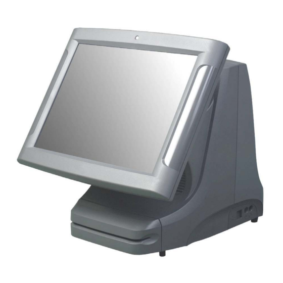
EQUIPMENT DESCRIPTION POS REGISTER Item Description 1. LCD display A screen that shows programming or order information. 2. Power indicator Shows that power is present. 3. Bar Code Reader Scanner for reading bar codes. This is a feature and may not be present on all registers. - Page 6 Item Description 11. Power switch Push in momentarily to turn “on”, push and hold to turn “off”. You can reach it by sliding your hand under the right side of the register toward the back. Leave the register on at all times, except when servicing the unit.
-
Page 7: Connector Well
CONNECTOR WELL Item Description 13. COMM serial port 1 Connects to coin dispensers, remote customer displays, remote order (RS-232-C) displays, EFT devices, printers, and other serial devices. 14. Printer port Connects to a cable from a printer—A Centronics-compatible. 15. LAN receptacle Connects to a LAN cable. -
Page 8: Specifications
SPECIFICATIONS ViGo POS Features: ♦ Processors F6100R – 2.0GHz Celeron Processor w/fan F6101R – 2.0GHz Pentium 4 Processor w/fan F6102R– 2.5GHz Celeron Processor w/fan F6103R – 2.4GHz Pentium 4 Processor w/fan F6104R – 2.8GHz Pentium 4 Processor w/fan ♦ Memory F6201R –... -
Page 9: Bios
BIOS Introduction This user manual describes the AMI BIOS setup program and configuration options of the ViGo motherboard. The BIOS setup program allows users to modify the basic system configuration. Starting Setup The AMI BIOS is activated when the computer is turned on. The setup program can be activated by pressing the F2 key as soon as the system is turned on. - Page 10 The following sections completely describe the configuration options found in the menu items at the top of the BIOS screen and listed above. Main The Main BIOS menu appears when the BIOS Setup program is entered. The Main menu gives an overview of the basic system information.
- Page 11 Use the System Date option to set the system date. Manually enter the day, month and year. Advanced Use the Advanced menu to configure the CPU and peripheral devices through the following sub-menus: WARNING: Setting the wrong values in the sections below may cause the system to malfunction.
-
Page 12: Cpu Configuration
CPU Configuration Use the CPU Configuration menu to view detailed CPU specifications and configure the CPU. BIOS Menu 3: CPU Configuration The CPU Configuration menu (BIOS Menu 3) lists the following CPU details: Manufacturer: Lists the name of the CPU manufacturer Brand String: Lists the brand name of the CPU being used Frequency: Lists the CPU processing speed FSB Speed: Lists the FSB speed... -
Page 13: Ide Configuration
IDE Configuration Use the IDE Configuration menu to change and/or set the configuration of the IDE devices installed in the system. BIOS Menu 4: IDE Configuration OnBoard PCI IDE Controller [Primary] Use the OnBoard PCI IDE Controller BIOS option to specify the IDE channels used by the onboard PCI IDE controller. - Page 14 IDE Master, IDE Slave Use the IDE Master and IDE Slave configuration menu to view both primary and secondary IDE device details and configure the IDE devices connected to the system.
- Page 15 Super IO Configuration Use the Super IO Configuration menu to set or change the configurations for the FDD controllers, parallel ports and serial ports. BIOS Menu 5: Super IO Configuration Serial Port Address Use the Serial Port Address option to select the Serial Port base address. Disabled No base address is assigned to Serial Port Port IRQ Options:...
-
Page 16: Hardware Health Configuration
Hardware Health Configuration The Hardware Health Configuration menu shows the operating temperature, fan speeds and system voltages. The values in image may not correspond to POS system, image is for reference only. BIOS Menu 6: Hardware Health Configuration The following system parameters and values are shown. The system parameters that are monitored are: System Temperatures: The following system temperatures are monitored System Temperature CPU Temperature... -
Page 17: Acpi Configuration
ACPI Configuration The ACPI Configuration menu configures the Advanced Configuration and Power Interface (ACPI) and Power Management (APM) options. BIOS Menu 7: ACPI Configuration ACPI Aware O/S [Yes] Use the ACPI Aware O/S option to enable the system to configure ACPI power saving options. ACPI can only be implemented if the system OS complies with the ACPI standard. - Page 18 Advanced ACPI Configuration BIOS Menu 8: ACPI Configuration ACPI 2.0 Features [No] EFAULT AMI OEMB table [Enabled] Enabled EFAULT Disabled Headless Mode [Disabled] Disabled EFAULT Enabled...
- Page 19 Event Log Configuration Use the Event Log Configuration menu to view or delete the system event log storing POSt and run-time errors and events. BIOS Menu 9: Event Log Configuration View Event Log Enable the View Event Log option to view all unread event entries in a display window. Mark all events as read Enable the Mark all events as read option to mark all unread events as read.
-
Page 20: Usb Configuration
USB Configuration Use the USB Configuration menu to read USB configuration information and configure the USB settings. BIOS Menu 10: USB Configuration USB Configuration The USB Configuration field shows the system USB configuration. The items listed are: Module Version: x.xxxxx.xxxxx USB Devices Enabled The USB Devices Enabled field lists the USB devices that are enabled on the system Legacy USB Support [Enabled]... - Page 21 PCI/PnP Use the PCI/PnP menu to configure advanced PCI and PnP settings. WARNING! Setting wrong values for the BIOS selections in the PCIPnP BIOS menu may cause the system to malfunction. BIOS Menu 11: PCI/PnP Configuration Plug & Play O/S [No] Use the Plug &...
- Page 22 Available IRQ addresses are: IRQ3 IRQ4 IRQ5 IRQ7 IRQ9 IRQ 10 IRQ 11 IRQ 14 DMA Channel# [Available] Use the DMA Channel# option to assign a specific DMA channel to a particular PCI/PnP device. Available The specified DMA is available to be used by PCI/PnP EFAULT devices Reserved...
-
Page 23: Boot Settings Configuration
Boot Settings Configuration Use the Boot Settings Configuration menu to configure advanced system boot options. BIOS Menu 13: Boot Settings Configuration Quick Boot [Enabled] Use the Quick Boot BIOS option to make the computer speed up the boot process. Disabled No POST procedures are skipped Enabled Some POST procedures are skipped to decrease the... - Page 24 the 10-keys on the keyboard, press the Number Lock key located on the upper left-hand corner of the 10-key pad. The Number Lock LED on the keyboard lights up when the Number Lock is engaged. Allows the Number Lock on the keyboard to be enabled EFAULT automatically when the computer system boots up.
-
Page 25: Boot Device Priority
Boot Device Priority Use the Boot Device Priority menu to specify the boot sequence from the available devices. Possible boot devices may include: FLOPPY DRIVE CD/DVD... - Page 26 Chipset Use the Chipset menu to access the NorthBridge configuration menu. WARNING! Setting the wrong values for the Chipset BIOS selections in the Chipset BIOS menu may cause the system to malfunction. BIOS Menu 14: Chipset...
- Page 27 Intel Brookdale-G NorthBridge Configuration Use the NorthBridge Configuration menu to configure the northbridge chipset. BIOS Menu 15:NorthBridge Chipset Configuration Intel ICH4 SouthBridge Configuration Use the SouthBridge Configuration menu to configure the southbridge chipset.
- Page 28 Power Key The Power menu allows the advanced power management options to be configured. BIOS Menu 16:Power Power Management/APM [Enabled] Use the Power Management/APM BIOS option to enable access to the advanced power management features. If this option is disabled, the only other option on the screen is the Power Button Mode. Disabled Disables the Advanced Power Management (APM) feature Enabled...
- Page 29 System Thermal [Disabled] Disables the System Thermal feature Disabled EFAULT Enabled Enables the System Thermal feature Power Button Mode [On/Off] Use the Power Button Mode BIOS to specify how the power button functions. On/Off When the power button is pressed the system is either turned EFAULT on or off Suspend...
- Page 30 Exit Use the Exit menu to load default BIOS values, optimal failsafe values and to save configuration changes. BIOS Menu 17:Exit Save Changes and Exit Use the Save Changes and Exit option to save the changes made to the BIOS options and to exit the BIOS configuration setup program.
- Page 31 PAR PHONE NUMBERS Service USA: 800.382.6200 Canada: 800.387.4963 Parts USA: 800.PAR.PART Canada: 800.387.4963 Sales Continental USA except New York: 800.448.6505 New York State Only: 800.533.6311 Outside Continental USA: 315-738-0600 Driver Support http://www.partech.com/pti_products_services/service_existing_customer.cfm...
Need help?
Do you have a question about the M60XX-XX and is the answer not in the manual?
Questions and answers