Table of Contents
Advertisement
INSTALLATION AND OPERATION MANUAL
5000
CONTACT LOCAL BUILDING OR FIRE OFFICIALS ABOUT RESTRICTIONS AND INSTALLATION
INSPECTION REQUIREMENTS IN YOUR AREA.
PLEASE READ THIS ENTIRE MANUAL BEFORE INSTALLATION AND USE OF THIS PELLET FUEL‐
BURNING ROOM HEATER. FAILURE TO FOLLOW THESE INSTRUCTIONS COULD RESULT IN
PROPERTY DAMAGE, BODILY INJURY OR EVEN DEATH.
250, rue de Copenhague, St‐Augustin‐de‐Desmaures (Quebec) Canada G3A 2H3
This manual is available for free download on the manufacturer's web site. It is a copyrighted
document. Re‐sale is strictly prohibited. The manufacturer may update this manual from time to
time and cannot be responsible for problems, injuries, or damages arising out of the use of
information contained in any manual obtained from unauthorized sources
Printed in Canada
www.osburn‐mfg.com
Stove Builder International Inc.
Tel: (418) 878‐3040 Fax: (418) 878‐3001
READ AND KEEP THIS MANUAL FOR REFERENCE
Safety tested according to ULC S627,
UL1482 and ASTM E1509 by Intertek
Testing Services and according to Oregon
Administrative Rules for Mobile Homes
814‐23‐900 through 814‐23‐909
.
45548A
29‐06‐2012
Advertisement
Table of Contents

Subscribe to Our Youtube Channel
Related Manuals for Osburn 5000


Summary of Contents for Osburn 5000
- Page 1 INSTALLATION AND OPERATION MANUAL 5000 Safety tested according to ULC S627, UL1482 and ASTM E1509 by Intertek Testing Services and according to Oregon Administrative Rules for Mobile Homes 814‐23‐900 through 814‐23‐909 CONTACT LOCAL BUILDING OR FIRE OFFICIALS ABOUT RESTRICTIONS AND INSTALLATION INSPECTION REQUIREMENTS IN YOUR AREA. PLEASE READ THIS ENTIRE MANUAL BEFORE INSTALLATION AND USE OF THIS PELLET FUEL‐...
- Page 2 5000 Pellet Stove Installation and Operation Manual THANK YOU FOR CHOOSING THIS OSBURN PELLET STOVE As one of North America’s largest and most respected pellet stove, wood stove and fireplace manufacturers, Stove Builder International takes pride in the quality and performance of all its products. We want to help you get maximum satisfaction as you use this product. In the pages that follow you will find general advice on pellet heating, detailed instructions for safe and effective installation, and guidance on how to get the best performance from this stove as you build and maintain your pellet heating system. We highly recommend that our pellet burning hearth products be installed and serviced by ...
-
Page 3: Table Of Contents
INTRODUCTION..............................5 About Pellet Heating ............................5 1.1.1 Top 10 Reasons for Buying a Pellet Stove ....................5 5000 Specifications .............................. 6 Overall Exterior Dimensions ..........................7 PART A – INSTALLATION ............................8 Installation Safety Information ..........................8 Installation Warnings, Cautions and Recommendations ..................8 Regulations Covering Pellet Stove Installation .................... - Page 4 5000 Pellet Stove Installation and Operation Manual Stove operation ..............................35 First Startup ............................... 35 Everyday Startup ..............................35 Running Out of Pellets ............................35 Refilling ................................35 Shutting Down Procedure ..........................36 Signs of an Overheating Stove ........................... 36 MAINTENANCE ..............................37 Stove Maintenance ............................. 37 8.1.1...
-
Page 5: Introduction
5000 Pellet Stove Installation and Operation Manual 1 INTRODUCTION 1.1 ABOUT PELLET HEATING Pellet stoves offer a dramatic improvement in the convenience of heating with solid fuel. Wood pellets are handled in bags and are therefore easily and cleanly stored. A single loading of a pellet stove can provide long hours of warmth. Pellet stoves also provide a special comfort associated with wood burning. The combination of fans delivering warm air currents and the direct comfort of radiant heat provides special satisfaction on a cold winter day. The heat provided is even and constant, due to the auto fuel feed responding to owner settings. Pellet stoves also offer strong environmental benefits; pellets not only reduce dependence on finite supplies of fossil fuels like oil and gas, but they also put to good use materials that would otherwise unnecessarily and ... -
Page 6: 5000 Specifications
5000 Pellet Stove Installation and Operation Manual 1.2 5000 SPECIFICATIONS Wood pellets, Wood and Hay pellets, Bark pellets and Fuel Type Switch Grass pellets. Test Standards (safety) ULC S627, ASTM E1509 and UL 1482 Heating capacity range* 500 to 2400 sq ft (46 to 223 m ) Input BTU range** From 8 500 BTU to 50 000 BTU Hopper capacity** 70 lb (32 Kg) Approximate Burn Time* 13 to 40 hours Shipping Weight 390 lb (177 kg) 23 5/8’’ W x 31 7/8’’ D x 35 13/16’’ H Overall Exterior Dimensions (600 mm x 799 mm x 909 mm) 3’’ or 4’’ depending on EVL (see Section 4.3 Equivalent Vent Vent system size Length (EVL)) Baffle material Stainless Steel Burn rate 1.5 lb to 5.5 lb per hour 3A for ignition cycle Energy consumption 1.8A for maximum continuous operation Electrical requirements 120VAC 15A Control board fuses Main: 7.5A‐250V fast‐blow fuse Convection blower: 5A‐250V fast‐blow fuse Combustion blower: 3A‐250V fast‐blow fuse Exhaust blower: 3A‐250V fast‐blow fuse ... -
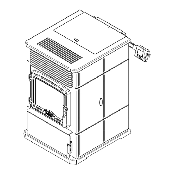
Page 7: Overall Exterior Dimensions
5000 Pellet Stove Installation and Operation Manual 1.3 OVERALL EXTERIOR DIMENSIONS A: FRESH AIR INTAKE B: EXHAUST _ ______________________________________________________________________________ 7 ... -
Page 8: Part A - Installation
5000 Pellet Stove Installation and Operation Manual PART A – INSTALLATION 2 INSTALLATION SAFETY INFORMATION 2.1 INSTALLATION WARNINGS, CAUTIONS AND RECOMMENDATIONS PROFESSIONNAL INSTALLATION IS HIGHLY RECOMMENDED. YOU MAY NEED TO OBTAIN A BUILDING PERMIT FOR THE INSTALLATION OF THIS STOVE AND ITS VENTING SYSTEM. CONSULT YOUR MUNICIPAL BUILDING DEPARTMENT OR FIRE DEPARTMENT BEFORE INSTALLATION TO DETERMINE THE NEED TO OBTAIN ONE. WE RECOMMEND THAT YOU ALSO INFORM YOUR HOME INSURANCE COMPANY TO FIND OUT IF THE INSTALLATION WILL AFFECT YOUR POLICY. THIS STOVE MUST BE CONNECTED TO A STANDARD 120V. 60 HZ GROUNDED ELECTRICAL ... - Page 9 5000 Pellet Stove Installation and Operation Manual DO NOT CONNECT THIS STOVE TO ANY OTHER EXISTING VENTING SYSTEM SERVING ANOTHER APPLIANCE. DO NOT CONNECT TO OR USE IN CONJUNCTION WITH ANY AIR DISTRIBUTION DUCTWORK. THE VENTING SYSTEM MUST BE COMPLETELY AIRTIGHT AND PROPERLY INSTALLED. ALL VENT CONNECTOR JOINTS MUST BE SEALED AND FASTENED IN ACCORDANCE WITH THE ...
-
Page 10: Regulations Covering Pellet Stove Installation
5000 Pellet Stove Installation and Operation Manual 2.2 REGULATIONS COVERING PELLET STOVE INSTALLATION When installed and operated as described in these instructions, this pellet stove is suitable for use as a freestanding heater in residential installations. In Canada, the CSA B365 Installation Code for Solid Fuel Burning Appliances and Equipment and the CSA C22.1 Canadian National Electrical Code are to be followed in the absence of local code requirements. In the USA, the ANSI NFPA 211 Standard for Chimneys, Fireplaces, Vents and Solid Fuel‐Burning Appliances and the ANSI NFPA 70 National Electrical Code are to be followed in the absence of local code requirements. This stove must be connected to a pellet vent system complying with the requirements for Pellet Vent in the standards UL 103, ULC S629M, ULC S609 and UL 641or to a code‐approved masonry chimney with a stainless steel flue liner. 2.3 BEFORE OPERATING YOUR STOVE Some minor installation and adjustment are required prior to use: If desired, LCD sliding support can be installed on the left at the back of the stove; (see ... -
Page 11: Clearances To Combustible Material
5000 Pellet Stove Installation and Operation Manual 3 CLEARANCES TO COMBUSTIBLE MATERIAL The clearances shown in this section have been determined by test according to procedures set out in safety standards ULC S627 (Canada), ASTM E1509 (U.S.A). When the pellet stove is installed so that its surfaces are at, or beyond, the minimum clearances specified, combustible surfaces will not overheat under normal and even abnormal operating conditions. WARNING: NO PART OF THE STOVE MAY BE LOCATED CLOSER TO COMBUSTIBLES THAN THE MINIMUM CLEARANCES SPECIFIED ON THE CERTIFICATION LABEL. CAUTION: NO PART OF THE PELLET VENT SYSTEM MAY BE LOCATED CLOSER TO COMBUSTIBLES THAN THE MINIMUM CLEARANCES SPECIFIED BY THE VENT MANUFACTURER. CAUTION: DO NOT USE MAKESHIFT MATERIALS OR MAKE ANY COMPROMISES WHEN INSTALLING THIS STOVE. 3.1 LOCATION OF THE CERTIFICATION LABEL Since the information given on the certification label affixed to the stove always overrides the ... -
Page 12: Back Wall Installation
5000 Pellet Stove Installation and Operation Manual 3.3 BACK WALL INSTALLATION For a back wall installation, in order to allow the LCD sliding support to move freely and fully extend, you should allow a minimum of 4″(105 mm) clearance from the side wall (B) and 3″(80 mm) clearance at the back of the stove, from the fresh air intake (A). However, if you wish to install the stove with minimum clearances (see table in Section 3.2 Minimum Clearances to Combustibles), it is possible to locate the LCD touch screen elsewhere but within the maximum length ... -
Page 13: Ceiling Clearances
5000 Pellet Stove Installation and Operation Manual 3.5 CEILING CLEARANCES For ceiling clearances refer to the table in Section 3.2 Minimum Clearances to Combustibles. 3.6 FLOOR PROTECTION For floor protection clearances refer to the following table. FLOOR PROTECTION LETTER CANADA USA E 18″ (460 mm) 6″ (155 mm) F N/A (USA only) 6″ (155 mm) G 8″ (205 mm) N/A (Canada only) H 8″ (205 mm) N/A (Canada only) CAUTION: THE STOVE MUST BE PLACED ON A CONTINUOUS (GROUTED JOINTS) ... -
Page 14: Venting System
5000 Pellet Stove Installation and Operation Manual 4 VENTING SYSTEM 4.1 GENERAL Even though the chimney draft is mechanical, a suitable venting system will ensure a natural draft which will prevent smoke spillage in your home if a power outage occurs. Moreover, a suitable venting system configuration will help getting the best efficiency out of your stove when installed in accordance with the required EVL (see Section 4.3 Equivalent Vent Length (EVL)). Even the best stove will not function safely and efficiently as intended if it is not connected to a suitable venting system. 4.2 RECOMMENDATIONS In Canada, we recommend that you use a listed pellet vent that meets the ULC S‐609‐M89/ORD C441‐M90 Standard. A pellet vent listed to ULC S629M is also suitable for installation with this ... -
Page 15: Termination Location
5000 Pellet Stove Installation and Operation Manual Here is an example to help you calculate Equivalent Vent Length. On the following figure the EVL can be calculated like this: 2 horizontal run of 1’ = (2 X 1’) X 1’ = 2’ of EVL 1 elbow 90° or "Tee" = 5’ of EVL 3 vertical length of 4’ = (3 X 4’) X 0.5’ = 6’ of EVL Total EVL = (2’ + 5’ + 6’) = 13’. EVL is less than 15’ therefore it is correct to use a 3’’ pipe. NOTE: Do not include the exterior wall termination in the EVL calculation. (45° elbow and termination) 4.4 TERMINATION LOCATION Termination should not be located so that ... -
Page 16: Permitted Termination Location
5000 Pellet Stove Installation and Operation Manual 4.4.1 PERMITTED TERMINATION LOCATION Canada: Min. Letter Description clearances A 12’’ (30 cm) Clearances above grade, veranda, porch, deck, or balcony B 36’’ (91 cm) Clearance to window or door that may be opened F 0’’ (0 cm) Clearance to outside corner Not to be installed above a meter/regulator assembly within 36" (91 H 36’’ (91 cm) cm) horizontally from the vertical center‐line of the regulator Clearance to gas service regulator vent outlet or within 36’’ (91 cm) of I 72’’ (183 cm) an oil tank vent or an oil tank fill inlet Clearance to non‐mechanical air supply inlet to building or the ... -
Page 17: Installation Configurations
5000 Pellet Stove Installation and Operation Manual United States: Not Less than 36’’ (91 cm) above any forced air inlet located within 120’’ feet (305 cm); Not Less than 4 feet below or horizontally from, or one foot above, any door, window or gravity air inlet into any building; Not Less than 24’’ (61 cm) from an adjacent building and not less than 84’’ (213 cm) above ... -
Page 18: Through Wall Installation (Main Floor Or Basement)
5000 Pellet Stove Installation and Operation Manual 4.5.2 THROUGH WALL INSTALLATION (MAIN FLOOR OR BASEMENT) 1. Position stove following clearances given in Section 3, Clearances to Combustible Material and following vent manufacturer’s instructions. Then locate the position of the exhaust pipe in the wall. 2. Install wall thimble as per vent manufacturer’s instructions. 3. Attach enough piping length to go through the wall thimble and extend at least 6 inches beyond the exterior wall. 4. Attach cap and seal outside wall thimbles with high temperature waterproof silicone sealant. CAUTION: TO REDUCE THE RISK OF SMOKE SPILLAGE THERE SHOULD ALWAYS BE AT LEAST ONE FOOT OF VERTICAL RISE FOR EACH FOOT OF HORIZONTAL RUN. IN ALL CASES, AT LEAST 3 FEET OF VERTICAL RISE IS NEEDED. WARNING: TERMINATION SHOULD NOT BE LOCATED SO THAT HOT EXHAUST GASES CAN BE A HAZARD. EXHAUST GASES CAN REACH TEMPERATURES OF 500ºF AND CAUSE SERIOUS BURNS. SEE SECTION 4.4.1 PERMITTED TERMINATION LOCATION. 18 _ _____________________________________________________________________________ ... -
Page 19: Through Roof Installation
5000 Pellet Stove Installation and Operation Manual 4.5.3 THROUGH ROOF INSTALLATION Position stove following clearances given in Section 3.2 Minimum Clearances to Combustibles and following vent manufacturer’s instructions. 2. Install a cleanout tee to the stove exhaust. If necessary, use a horizontal additional length between the exhaust and the tee. If you wish to center the vertical part of the vent with the stove, a 45° elbow and a tee can be used to route the pipe from the ... -
Page 20: Through A Prefabricated Chimney
5000 Pellet Stove Installation and Operation Manual 4.5.4 THROUGH A PREFABRICATED CHIMNEY The best method to make an installation through a prefabricated chimney is to run a 3" stainless steel liner inside the prefabricated chimney (or a 4" stainless steel liner depending on the Equivalent Vent Length calculated in Section 4.3 Equivalent Vent Length (EVL)). 1. Position stove following clearances given in Section 3.2 Minimum Clearances to Combustibles and following vent manufacturer’s instructions. 2. Install a cleanout tee to the stove exhaust. ... -
Page 21: Through An Existing Masonery Fireplace
5000 Pellet Stove Installation and Operation Manual 4.5.5 THROUGH AN EXISTING MASONERY FIREPLACE 1. Position stove, following clearances shown in Section 3.2 Minimum Clearances to Combustibles and following vent manufacturer’s instructions. 2. Build and Install a blocking plate inside the chimney to seal the fireplace damper. Stainless steel plate and screws are recommended. Cut a hole for the exhaust ... -
Page 22: Through An Existing Masonery Chimney
5000 Pellet Stove Installation and Operation Manual 4.5.6 THROUGH AN EXISTING MASONERY CHIMNEY 1. Position stove following clearances shown in Section 3.2 Minimum Clearances to Combustibles and following vent manufacturer’s instructions. 2. Mark the center of the hole where the vent pipe will go through the masonry chimney. 3. It is necessary to make a hole in the masonry with a diameter of 4 " around the mark for a 3'' pipe. For a 4'' pipe, a hole of 5'' in diameter. 4. Build and install flashing above the ... -
Page 23: Part B - Operation
5000 Pellet Stove Installation and Operation Manual PART B ‐ OPERATION 5 GENERAL INFORMATION 5.1 OPERATION WARNINGS, CAUTIONS AND RECOMMENDATIONS KEEP THIS MANUAL FOR REFERENCE. DURING THE FIRST FEW FIRES, YOUR STOVE WILL EMIT AN ODOR AND A SMALL AMOUNT OF FUMES AS THE HIGH TEMPERATURE PAINT CURES OR BECOMES SEASONED TO THE METAL. MAINTAINING SMALLER FIRES WILL MINIMIZE THIS. AVOID PLACING ITEMS ON STOVETOP DURING THIS PERIOD TO AVOID DAMAGING THE PAINT SURFACE. MAKE SURE THE ROOM IS WELL‐VENTILATED. OPEN WINDOWS. ODORS AND FUMES RELEASED DURING THIS PROCESS ARE UNPLEASANT BUT THEY ARE NOT TOXIC. ONCE YOU HAVE BURNED THE FIRST 40LBS OF PELLETS, IT IS RECOMMENDED TO INSPECT THE STOVE AND THE VENTING SYSTEM TO MAKE SURE THAT THERE IS NO LEAKS. HOT WHILE IN OPERATION, KEEP CHILDREN, CLOTHING AND FURNITURE AWAY. CONTACT ... - Page 24 5000 Pellet Stove Installation and Operation Manual NEVER TRY TO REPAIR OR REPLACE ANY PART OF THE STOVE UNLESS INSTRUCTIONS ARE GIVEN BY THE MANUFACTURER. ALL OTHER WORK SHOULD BE DONE BY A TRAINED TECHNICIAN. DO NOT OPERATE THE STOVE IF THE FLAME BECOMES DARK AND SOOTY OR IF THE BURN ...
-
Page 25: Zone Heating And How To Make It Work For You
5000 Pellet Stove Installation and Operation Manual THIS STOVE IS DESIGNED TO PROVIDE THE OPTIMUM PROPORTIONS OF FUEL AND AIR TO THE FIRE IN ORDER TO BURN FREE OF SMOKE AND SOOT. ANY BLOCKAGE OF THE AIR SUPPLY TO OR FROM THE STOVE WILL SERIOUSLY DECREASE ITS PERFORMANCE AND WILL BE EVIDENT BY A SMOKING EXHAUST, A SOOT BUILDUP ON THE WINDOW AND ON OUTSIDE WALLS. FOR BEST OPERATION, THE ASH CONTENT OF THE PELLET FUEL SHOULD BE LESS ... -
Page 26: Combustible
5000 Pellet Stove Installation and Operation Manual home if needed. The manufacturer cannot be responsible for additional heating costs associated with the use of an alternative heat source in case of stove failure or power outage. Your success with zone heating will depend on several factors: Proper stove size, stove location, heating area, house layout and insulation and your climate zone. 5.2 COMBUSTIBLE 5.2.1 PROPER FUEL Each type of pellet has its properties and will burn differently. The amount of ashes produced can also vary greatly. Factory‐approved pellets are those ¼” or 5/16” in diameter and not over 1” long. Longer or thicker pellets will prevent proper pellet feed. The bottom‐feed system of this stove is designed and tested specifically for use with four different types of pellets: standard wood pellets, 100% bark pellets, sawdust/hay mix pellets and switch grass pellets. Pellet type Composition Ash quantity Ignition Wood pellets Made of hard or Small quantity Easy soft wood Wood ... -
Page 27: Stove Controls
5000 Pellet Stove Installation and Operation Manual 6 STOVE CONTROLS 6.1 GENERAL INFORMATION The stove uses a LCD touch screen, the latest technology in control devices. The blowers and feed system are controlled from this screen. The LCD touch screen is factory‐installed on the right hand side of the stove when facing it. See Appendix B: LCD Sliding Bracket Mounting for left hand side installation. 6.1.1 LCD TOUCH SCREEN CONTROLS, OPERATION AND CONFIGURATION The LCD control is an electronic visual display as well as a touch screen that will light‐up as you touch any location on the display area. The Main Status Page will then display different icons ... - Page 28 5000 Pellet Stove Installation and Operation Manual Description of each main status page icon: Indicates that the stove is in the manual mode. It will therefore run continuously on the selected setting until it is manually modified, turned OFF or if the stove runs out of pellets (see Section 6.1.8 Selecting Manual or Thermostat Mode). Indicates that the stove is in the thermostat mode. The red waves indicate that the thermostat is calling for heat. The waves will disappear once the thermostat has reached room temperature setting (see Section 6.1.8 ...
-
Page 29: Configuration And Operation Diagram
5000 Pellet Stove Installation and Operation Manual 6.1.2 CONFIGURATION AND OPERATION DIAGRAM Select the language displayed on the LCD screen (french, english) Select the pilot mode COOL COOL (30,45,60 minutes, always on or always off) This page will help the user troubleshoot the unit if 45 MIN Select the scale of... -
Page 30: Changing Temperature Unit (⁰F Or ⁰C)
5000 Pellet Stove Installation and Operation Manual 6.1.5 CHANGING TEMPERATURE UNIT (⁰F OR ⁰C) From the main status page, choose the letter icon . Select “SETUP” and then “⁰F / ⁰C”. Select icon F or C in order to display temperatures in the desired unit . 6.1.6 ADJUSTING THE COMBUSTION LEVEL (HEAT OUTPUT) COMBUSTION LEVEL FUEL QUALITY ADJUSTMENT POSITION THE CURSOR TO SET THE AUGER MOTOR 1 ‐ COMBUSTION LEVEL COMBUSTION FAN ‐ EXHAUST FAN ‐ PILOT FUEL Q. SAVE & EXIT... -
Page 31: Convection Fan Speed Reduction (Optional)
5000 Pellet Stove Installation and Operation Manual 6.1.6.1 PILOT ADJUST. (Pilot Settings Adjustment) The “PILOT SETTINGS ADJUSTEMENT” will allow you to modify default settings by +/‐ 5% for auger motor 1 and +/‐ 10% for exhaust fan, but will only apply during pilot cycle: To restore default setting, select “DEFAULT”. Refer to following section for settings adjustments explanation. 6.1.6.2 FUEL Q. ADJUST (Fuel Quality Adjustment) The “FUEL QUALITY ADJUSTMENT” will allow you to modify default settings by +/‐ 5% for auger motor 1 and +/‐ 10% for combustion and exhaust fan. To restore default setting, select “DEFAULT”. Here are some situations where you may want to adjust these components: Average speed of auger motor #1: You may want to increase the auger motor #1 speed if fire goes out when combustion level is at its minimum setting. When burning poor quality pellets you may also need to reduce the auger motor speed to avoid unburned pellets to fall into the ash drawer at any combustion level. Speed of combustion fan: You may want to reduce combustion fan speed if fire goes out when combustion level is at ... -
Page 32: Selecting Manual Or Thermostat Mode
5000 Pellet Stove Installation and Operation Manual FAN SPEED CONTROL SLIDE THE CURSOR TO SELECT THE FAN SPEED BACK SAVE & EXIT Fan with red arrows icon will display on the Main Status Page as you “SAVE & EXIT”. Fan speed reduction will be more noticeable on higher combustion level settings. To deactivate the fan speed reduction, select “OFF” from this page. If overheating occurs, fan speed reduction will be automatically deactivated and an envelope icon will replace the fan icon on the Main Status Page. Press on the envelope icon to view the warning message. Meanwhile, the convection fan will work at its highest setting until the stove ... -
Page 33: Selecting The Pilot Cycle
5000 Pellet Stove Installation and Operation Manual 6.1.9 SELECTING THE PILOT CYCLE Note: This icon will be visible on the Main Status Page only on thermostat mode. To change the pilot cycle press the hourglass icon , or, from the Main Status Page, choose the letter icon then select “SETUP” and “PILOT MODE”. You can choose from one of the five different pilot cycles: "ALWAYS OFF", "30 MINUTES", “45 MINUTES”, “60 MINUTES” or "ALWAYS ON". The selected cycle will be displayed under the ... -
Page 34: Filling Or Purging Auger Housing
5000 Pellet Stove Installation and Operation Manual 6.1.10 FILLING OR PURGING AUGER HOUSING Note: This function is disabled when the stove is running. To fill or purge the auger housing press the auger icon and select either “FEED AND START”, “PURGE SCREW” or “ADD PELLETS” in the displayed page. 6.1.10.1 Feed and Start Use this option when you start the stove for the first time of the season or after the hopper ran out of pellets. The auger will turn for one minute then the stove will automatically start an ignition cycle. 6.1.10.2 Purge Screw Use this option to empty the auger at the end of the season. When selected, the auger will turn for two minutes. 6.1.10.3 Add Pellets Use this option to manually feed more pellet in the burn pot. When selected, the auger will turn for 20 seconds. 34 _ _____________________________________________________________________________ ... -
Page 35: Stove Operation
5000 Pellet Stove Installation and Operation Manual 7 STOVE OPERATION 7.1 FIRST STARTUP Before starting your stove, make sure that the burn pot, the baffles and the maintenance access panels are properly installed. Also make sure that venting system is properly sealed and all doors are closed. Make sure the hopper is full; the hopper lid is closed and select the desired mode (manual or thermostat). Press the auger icon on the Main Status Page followed by “FEED AND START” button in the displayed page. If fire doesn’t start within 20 minutes, a warning code ... -
Page 36: Shutting Down Procedure
5000 Pellet Stove Installation and Operation Manual NOTE: Keep hopper lid closed at all times except when refilling. Do not overfill the hopper. 7.5 SHUTTING DOWN PROCEDURE To turn your stove off, press the “ON/OFF” icon on the Main Status Page. The flame at the center of the icon will disappear when the stove is turned off. The cooling cycle will take a few minutes and the blowers will continue to work while the stove is cooling down. 7.6 SIGNS OF AN OVERHEATING STOVE Under normal conditions, the flame should have a bright yellow color and be very active, but stable (see Appendix C: Flame Characteristics). If you see the flame getting lazy, very high and ... -
Page 37: Maintenance
5000 Pellet Stove Installation and Operation Manual 8 MAINTENANCE 8.1 STOVE MAINTENANCE 8.1.1 RECOMMENDED MAINTENANCE SCHEDULE Use this as a guide under average use conditions. Weekly Twice a year Annually Components or after or after or +/‐ 250 pounds +/‐ 1 tons per 2 tons of pellets Baffle Vacuum Bottom airwash inlet Vacuum Burn Pot Brush / Vacuum Glass Clean Ash Drawer Empty / Vacuum Combustion Chamber Vacuum Vacuum / Brush* Heat Exchanger Tubes ... -
Page 38: Cleaning The Baffle, The Heat Exchangers And The Combustion Chamber
5000 Pellet Stove Installation and Operation Manual 8.1.2 CLEANING THE BAFFLE, THE HEAT EXCHANGERS AND THE COMBUSTION CHAMBER Remove and clean the three parts of the baffle that are located inside the combustion chamber. Use the small metal tabs to remove the panels in the order shown on the following pictures. Vacuum heat exchanger tubes. 1 2 8.1.3 CLEANING THE BURN POT Burn pot must stay clean and holes should not be obstructed by combustion residues (ashes, ... - Page 39 5000 Pellet Stove Installation and Operation Manual 1. Clean the burn pot using the scraper provided with the stove or a brush. 2. Release the clips on both sides of the burn pot then, remove the burn pot by lifting and pulling it out. Once the burn pot is removed make sure all holes are clean. Clean thoroughly under the burn pot with an ash vacuum to remove ashes that may have accumulated. 3. If necessary, clean the air intake channel. To reach the air intake channel clean out trap, open the ash drawer access door and remove the ash drawer. Unscrew the wing nut to open the clean out trap. Vacuum the combustion residues. _ _____________________________________________________________________________ 3 9 ...
-
Page 40: Ash Removal
5000 Pellet Stove Installation and Operation Manual 4. Verify that the clean out trap gasket is still in good condition, replace it if needed. 8.1.4 ASH REMOVAL 1. To empty the ash drawer of its contents, open the ash pan access door by lifting the latch on the right hand side. 2. Vacuum around the ash drawer and at the bottom of the combustion chamber. WARNING: ASH PAN MUST BE IN PLACE AND THE ASH PAN ACCESS DOOR MUST BE KEPT CLOSED WHEN THE STOVE IS IN USE. 40 _ _____________________________________________________________________________ ... -
Page 41: Cleaning The Air Wash System
5000 Pellet Stove Installation and Operation Manual 8.1.5 CLEANING THE AIR WASH SYSTEM Vacuum the ashes that may have accumulated in the airwash system inlet between the bottom glass retainer and the glass. This will allow an optimum air flow along the inside portion of the glass and prevents the glass from sooting‐up. 8.1.6 GLASS CARE ... -
Page 42: Door Gasket Maintenance
5000 Pellet Stove Installation and Operation Manual WARNING: REPLACEMENT GLASS SHOULD ONLY BE PURCHASED FROM AN AUTHORIZED DEALER (SEE “REPLACEMENT PARTS’’ SECTION). TEMPERED GLASS OR ORDINARY GLASS WILL NOT WITHSTAND THE HIGH TEMPERATURES OF THE STOVE. WARNING: IF YOU HAVE TO CHANGE THE DOOR GLASS, MAKE SURE YOU INSTALL THE NEW GASKETS AT THE SAME PLACE AS THE ORIGINAL IN ORDER TO KEEP THE AIRWASH WORKING ... - Page 43 5000 Pellet Stove Installation and Operation Manual Clean and vacuum any dirt or ash build‐up in the exhaust channels and exhaust blower housing being careful not to damage the blower’s blades. Use the scraper provided with the stove to clean heat exchanger outlet. Make sure the gaskets are still in good condition, replace them if needed. _ _____________________________________________________________________________ 4 3 ...
-
Page 44: Venting System Maintenance
5000 Pellet Stove Installation and Operation Manual 8.2 VENTING SYSTEM MAINTENANCE CAUTION: REGULARLY EXAMINE THE VENTING SYSTEM, THE JOINTS, AND THE SEALING TRIMS TO ENSURE THAT THE SMOKE AND THE COMBUSTION GASES ARE NOT DRAWN BY THE CONVECTION BLOWER. The most efficient method to sweep the venting system is by using a 3’’ or 4’’ pellet brush ... -
Page 45: Troubleshooting
5000 Pellet Stove Installation and Operation Manual 9 TROUBLESHOOTING When you have issues with your stove, your first reaction may be to call technical support. This section will help you save time and money by enabling you to solve simple problems by yourself. Most common problems are generally caused by the following five factors: 1. Wrong operation or lack of maintenance; 2. Bad installation; 3. Poor quality combustible; 4. Component failure; 5. Factory defect. The stove is equipped with a pc board that allows the stove to diagnose itself. It is thus important not to unplug the stove if there is an issue with it. First, because unplugging the stove will disable all the security features of the stove, and second, because you will not be able to see the error code given by the stove to understand what is the problem. It is thus important to read carefully this section before calling technical support. ... - Page 46 5000 Pellet Stove Installation and Operation Manual WARNING: RISK OF ELECTRICAL SHOCK. IF YOU NEED TO MANUALLY TEST, MANIPULATE OR REPLACE ANY COMPONENTS, THE STOVE NEEDS TO BE DISCONNECTED FROM THE WALL OUTLET. To validate the status of a component, you need to go to the “TROUBLESHOOT” page. From the Main Status Page, Press the “LETTER” icon and choose “TROUBLESHOOT” in the menu. ...
-
Page 47: Testing Components
5000 Pellet Stove Installation and Operation Manual 9.2 TESTING COMPONENTS If you suspect an electrical component to be defective, you can test it from the “TROUBLESHOOT” page. From the Main Status Page, Press the “LETTER” icon and choose “TROUBLESHOOT” in the menu. Page 4 and 5 will allow you to test every electrical component. Note that you will be COOL able to test only components when the stove is cold (showing this icon ). For example, if you press on the white square next to “GEAR MOTOR 1”, the auger 1 will turn for 30 seconds. This will give you the possibility to see the auger running and hear the motor running as well. PAGE 4 GEAR MOTOR 1 GEAR MOTOR 2 IGNITOR EXIT 9.3 MAIN ERROR CODES, POSSIBLE CAUSES AND SOLUTIONS WARNING: RISK OF ELECTRICAL SHOCK. IF YOU NEED TO MANUALLY TEST, MANIPULATE OR ... -
Page 48: Blocked Flue
5000 Pellet Stove Installation and Operation Manual NOTE: IF YOU NEED TO CONTACT YOUR DEALER OR TECHNICAL SUPPORT, MAKE SURE TO HAVE THE MODEL OF YOUR STOVE AND THE SERIAL NUMBER ON HAND. (THEY CAN BE FOUND ON THE CERTIFICATION LABEL INSIDE THE HOPPER LID). THE FOLLOWING MAY HAVE CAUSED YOUR THE FOLLOWING MAY HAVE CAUSED YOUR BLOCKED FLUE PROBLEM (BLOCKED FLUE): PROBLEM (BLOCKED FLUE): THE PRESSURE SWITCH WIRE THE PRESSURE TAP IS BLOCKED THE FLUE IS BLOCKED OR... - Page 49 5000 Pellet Stove Installation and Operation Manual THE FOLLOWING MAY HAVE CAUSED YOUR NO FUEL PROBLEM (NO FUEL): THE STOVE RAN OUT OF PELLETS THE EXHAUST THE BURN POT HOLES ARE BLOCKED THE AUGER JAMMED TEMPERATURE INDICATES THE AUGER MOTOR FAILED THAT THERE IS NO FIRE IN ...
- Page 50 5000 Pellet Stove Installation and Operation Manual THE FOLLOWING MAY HAVE CAUSED YOUR FAILED IGNITION PROBLEM (FAILED IGNITION): THE EXHAUST INADEQUATE FUEL IS USED TEMPERATURE HAS NOT THE IGNITER IS DEFECTIVE THE FLUE TEMPERATURE SENSOR REACHED ITS START-UP FAILED VALUE AFTER TWO CONSULT OWNER’S MANUAL FOR...
- Page 51 5000 Pellet Stove Installation and Operation Manual THE FOLLOWING MAY HAVE CAUSED YOUR AUGER FUSE PROBLEM (AUGER FUSE): THE AUGER IS JAMMED THE AUGER MOTOR IS DEFECTIVE THE AUGER FUSE BLEW UP THE WIRING HARNESS SHORTED CONSULT OWNER’S MANUAL FOR MORE DETAILS...
-
Page 52: Hopper Lid Open
5000 Pellet Stove Installation and Operation Manual The flue is not properly installed. Make sure the venting system meets the criteria in the installation section of this manual as well as the venting system manufacturer’s instructions. The flue is blocked or needs cleaning. One of the following components is obstructed or blocked; air intake shutter, combustion blower, burn pot, heat exchangers and channels, exhaust blower and or venting system. Refer to the maintenance section. The stove needs maintenance. Refer to maintenance section. The burn pot is not installed properly. Make sure the burn pot is well installed and locked in ... - Page 53 5000 Pellet Stove Installation and Operation Manual Power was interrupted while burning. After the cool down cycle, the stove will restart using the last settings. Press “RESET” to go back to the Main Status Page. Note: For a short power failure (less than 5 seconds), the stove will continue to function at the selected speed. SMOKE SMELL Venting system leaks. Inspect all vent connections. This is a pressurized venting system. All vent connector joints must be sealed and fastened in accordance with the pellet vent manufacturer's instructions to ensure consistent performance and avoid smoke and ash spillage. Worn gasket. Gaskets may be leaking (Doors, clean out traps, etc). Make sure that all gaskets are in good condition and replace them with original parts if necessary. Make sure the door is well adjusted (see Section 8.1.9 Door Adjustment). Negative pressure. A faint wood‐burning odor during ignition or shut down is normal. Although, if this increases beyond normal or if you notice an unusual soot build‐up on walls or furniture, check your venting system carefully for leaks and make sure all gaskets are in good condition. Also, ...
-
Page 54: Wiring Diagram
5000 Pellet Stove Installation and Operation Manual 10 WIRING DIAGRAM 54 _____________________________________________________________________________ ... -
Page 55: Fuses Access
5000 Pellet Stove Installation and Operation Manual 11 FUSES ACCESS WARNING: UNPLUG THE STOVE BEFORE CHANGING THE FUSES. All fuses are located inside the housing of the electronic board; the housing is on the back of your stove. Unplug your stove and turn the four spring clip to open the housing. _____________________________________________________________________________ 55 ... -
Page 56: Component Location
5000 Pellet Stove Installation and Operation Manual 12 COMPONENT LOCATION 56 _____________________________________________________________________________ ... -
Page 57: Exploded View And Replacement Parts
5000 Pellet Stove Installation and Operation Manual 13 EXPLODED VIEW AND REPLACEMENT PARTS _ _____________________________________________________________________________ 5 7 ... - Page 58 5000 Pellet Stove Installation and Operation Manual IMPORTANT: THIS IS DATED INFORMATION. When requesting service or replacement parts for your stove, please provide the model number and the serial number. We reserve the right to change parts due to technology upgrade or availability. Contact an authorized dealer to obtain any of these parts. Never use substitute materials. Use of non‐approved parts can result in poor ...
- Page 59 5000 Pellet Stove Installation and Operation Manual ITEM DESCRIPTION SE64379 EXHAUST BLOWER MAINTENANCE ACCESS DOOR SE64375 EXHAUST CHANEL ASSEMBLY 21384 EXHAUST GASKET 44095 THERMISTOR 44144 EXHAUST FAN 21382 OUTLET EXHAUST BLOWER GASKET PL64462 BLOWER OUTLET SPACER PL64463 ROUND EXHAUST PLATE...
- Page 60 5000 Pellet Stove Installation and Operation Manual ITEM DESCRIPTION 44059 THERMODISC 36T11 L250‐25 AUTOMATIC 99999 BUILD TO ORDER PL64337 TOP REAR PANEL PL64259 BOTTOM REAR PANEL 60036 THERMOSTAT TERMINAL 60196 POWER CORD RECEPTACLE 60331 POWER CORD 6' SE64363 COMBUSTION AIR INLET BOX...
-
Page 61: Appendix A: Horizontal And Vertical Vent Chart
5000 Pellet Stove Installation and Operation Manual APPENDIX A: HORIZONTAL AND VERTICAL VENT CHART Possible Horizontal vent length (feet) For example, let’s imagine an installation consisting of a horizontal vent coming out at the back of the stove on a total distance of 8 feet. This horizontal run is followed by a tee and a 6‐foot vertical rise. This type of installation is not acceptable. As you can see, the vent termination is clearly outside the allowed configuration zone on the ... - Page 62 5000 Pellet Stove Installation and Operation Manual Instead, if the installation consisted of a horizontal vent coming out at the back of the stove on a total distance of 4 feet, followed by a tee and a 6‐foot vertical rise, it would be acceptable. The installation end should be within the allowable configuration zone on the chart since it would have at least one foot of vertical rise for each foot of horizontal run. Furthermore, the total vertical rise would be at least 3‐foot high. WARNING: To reduce the risk of smoke spillage there should always be at least one foot of vertical rise for each foot of horizontal run. In all cases, at least 3 feet of vertical rise is needed. 62 _ _____________________________________________________________________________ ...
-
Page 63: Appendix B: Lcd Sliding Bracket Mounting
5000 Pellet Stove Installation and Operation Manual APPENDIX B: LCD SLIDING BRACKET MOUNTING Step 1 The LCD sliding bracket is preassembled on the right hand side when facing the stove. To reverse the assembly to a left side configuration, extend the rail with the LCD support (E) in order to access the two screws (A) which secures the rail mechanism to the mounting bracket. Remove the screws, rotate the rail 180° and reassemble the rail to the mounting bracket using the screws previously removed. Step 2 ... - Page 64 5000 Pellet Stove Installation and Operation Manual Step 3 Take the Telco black wire (D) which is located on the rear bottom panel and plug it into the back of the LCD touch screen interface receptacle. Step 4 Finally, secure the LCD touch screen housing (F) on the rail (E). 64 _ _____________________________________________________________________________ ...
-
Page 65: Appendix C: Flame Caracteristics
5000 Pellet Stove Installation and Operation Manual APPENDIX C: FLAME CARACTERISTICS Efficient flame An efficient flame should be bright but not too vigorous. The flame should also have a yellow to bright look. There should also be some small embers or spark exiting the flame and burn pot. The following picture is the flame pattern that will ... -
Page 66: Appendix D: Installing A Thermostat
5000 Pellet Stove Installation and Operation Manual APPENDIX D: INSTALLING A THERMOSTAT Using a thermostat will help you maintain a constant temperature throughout the house. A low voltage thermostat is required. A fixed wall mount or hand held model can be used. Note: Thermostat manufacturer’s instruction always overrides the information published in the following section. Thermostat location Location of the thermostat is very important to obtain comfort and efficiency from your stove. Locate the thermostat 4 to 5 feet above the floor in accordance with applicable building codes. ... - Page 67 5000 Pellet Stove Installation and Operation Manual Here is an example of what your thermostat could look like: Connect one wire on “RH” and the other wire on “W”. Red wire jumper can be left installed. For further information refer to the manufacturer’s instructions. Wireless thermostat If you are using a wireless thermostat or a hand held thermostatic remote control, connect the two thermostat wires to the terminal block located at the rear on the right hand side of the stove while facing it. If the receiver wires are equipped with quick‐connect terminals you can connect them directly to the stove’s wiring harness. ...
-
Page 68: Appendix E: Mobile Home Installation
5000 Pellet Stove Installation and Operation Manual APPENDIX E: MOBILE HOME INSTALLATION Anchor the stove WARNING: FOR MOBILE HOME INSTALLATION, IT IS MANDATORY TO CONNECT THE STOVE TO AN OUTSIDE COMBUSTION AIR SOURCE. (SEE APPENDIX F) When installed in a mobile home, the stove must be anchored to the floor with two screws. Use the two holes located for this purpose on each side of the pedestal, as shown on the following image. 68 _ _____________________________________________________________________________ ... -
Page 69: Appendix F: Combustion Air Supply
5000 Pellet Stove Installation and Operation Manual APPENDIX F: COMBUSTION AIR SUPPLY WARNING: FOR MOBILE HOME INSTALLATION, IT IS MANDATORY TO CONNECT THE STOVE TO AN OUTSIDE COMBUSTION AIR SOURCE. INSULATED PIPE SHOULD NEVER EXCEED 10 FEET. It is recommended to install an outside air inlet in or near the room where the stove is installed. When doing so, it is preferable to choose a wall which is not exposed to dominant winds, depending on the conditions surrounding your house. INSULATED PIPE AIR SUPPLY AIR INLET EXTERIOR WALL An insulated 3” inside diameter metallic pipe, either flexible or rigid, must be attached to the fresh air intake (A). A rodent guard (minimum ¼” wire mesh) must be used at the termination. All connections must be secured and airtight by either using the appropriately sized hose clamp and/or UL‐181‐AP foil tape. _ _____________________________________________________________________________ 6 9 ... - Page 70 5000 Pellet Stove Installation and Operation Manual Also make sure that the fresh air intake backdraft shutter (A) works freely. The fresh air intake backdraft shutter is located at the middle of the stove’s right hand side. Sources of Outside Combustion Air You can draw air from a ventilated crawl space underneath the floor. You can draw air directly from an outside wall, behind the stove. NOTE: The stove exhaust blower produces a negative pressure in the room. It draws air from the inside to the outside. In the same way, other appliances can also create a bigger negative ...
-
Page 71: Appendix G: Installing The Door Overlay
5000 Pellet Stove Installation and Operation Manual APPENDIX G: INSTALLING THE DOOR OVERLAY In order to complete the assembly of your Osburn 5000, you need to install the door overlay (A). See figure below for installation instructions: 1‐ Remove the wooden handle which is secured by a Philips type screw and a washer. 2‐ Position the overlay on the door frame and secure it in place from behind using the 4 screws (B). 3‐ Once the overlay is installed, put back the wooden handle, the washer and screw in place. Note: It is not necessary to remove the glass to install the overlay. _ _____________________________________________________________________________ 7 1 ... -
Page 72: Osburn Limited Lifetime Warranty
5000 Pellet Stove Installation and Operation Manual OSBURN LIMITED LIFETIME WARRANTY The warranty of the manufacturer extends only to the original consumer purchaser and is not transferable. This warranty covers brand new products only, which have not been altered, modified nor repaired since shipment from factory. Proof of purchase (dated bill of sale), model name and serial number must be supplied when making any ...
Need help?
Do you have a question about the 5000 and is the answer not in the manual?
Questions and answers