
Related Manuals for JBL DSC260


Summary of Contents for JBL DSC260
- Page 1 DSC260 Digital System Controller Owners Manual 8500 Balboa Blvd. Northridge, CA 91329...
-
Page 2: Table Of Contents
DSC260 Preliminary Owners Manual Revision 0.9 ABLE OF ONTENTS 1.0 INTRODUCTION ............................1 2.0 GETTING STARTED..........................2 2.1 U .............................. 2 NPACKING 2.2 M ......................... 2 ECHANICAL OUNTING 2.3 AC P ........................2 OWER ONNECTIONS 2.4 A ..........................2 UDIO ONNECTIONS 2.5 C... - Page 3 NEED MORE Q ON NPUTS OR UTPUTS 12.0 SPECIFICATIONS ..........................25 APPENDIX A: CONNECTOR WIRING INFORMATION................. 26 APPENDIX B: OUTPUT ASSIGNMENT MATRIX FOR JBL SYSTEMS..........27 APPENDIX C: MIDI IMPLEMENTATION ....................29 DSC-260 M ........................29 YSEX ORMAT ........................29...
-
Page 4: Safety Information
Web: www.jblpro.com The information contained in this document is confidential and copyright of JBL Professional. To convey its contents, in part or in whole to any third party without prior written authorization is a violation of the copyright. (c) JBL Professional 1997. -
Page 5: Introduction
DSC260 offers unparalleled performance for touring, fixed installation and monitoring requ irements. The DSC260 can be set up in many different configurations offering ultimate flexibility. Mono, two way and three way defaults are included. The user can also program additional configurations such as mono four, five or six way. Other configurations include mono four way with the second input feeding either a separate 2 way systems such as a down fill or delay cluster. -
Page 6: Getting Started
2.3 AC Power Connections: A 3-wire grounded outlet must always be used. The DSC260 will accept input AC from 100 - 240 Volts, 50-60 Hz. -
Page 7: A Quick Start
Minus visible. Press RECALL after the cursor is on the setting. 4. Connect the console outputs to the inputs of the DSC260. Left to A and Right to B. In the case of a mono system, use input A. 5. Connect the outputs of the controller to the amplifier input channels maintaining the Left and Right identification. -
Page 8: General Operation
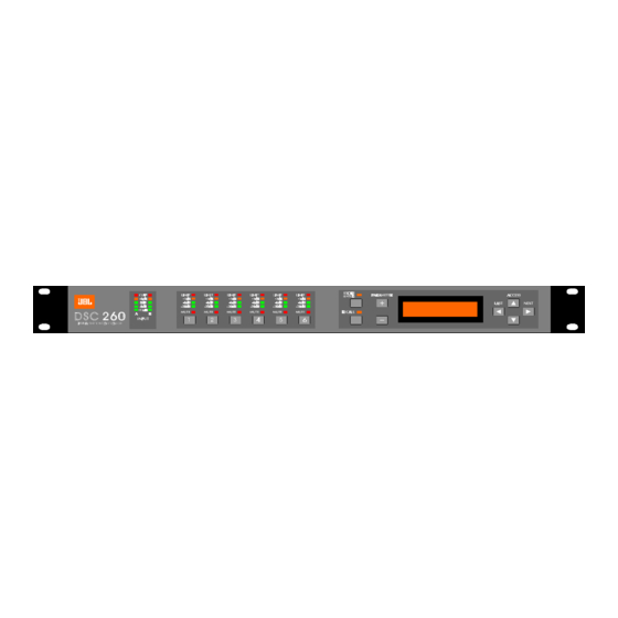
Revision 0.9 General Operation Figure 2 DSC260 Front Panel 4.1 LED Input Bargraphs The input bargraphs are peak responding to the input signal and also indicates digital clipping. The inputs always show the input level as calibrated to the XLR inputs. i.e. (+20 dBu=Maximum Input) -3dB, -6dB, -12dB and a signal present show the level below maximum input. -
Page 9: Access Buttons
The Up and Down Access keys move the user between rows. The Next and Last keys step the user through the variables within the currently selected row. See section 9.0 on ASSIGNABLE EQ for the use of Next and Last to assign EQ to a channel. Figure 5 DSC260 Programming Grid... -
Page 10: Ultility Control Parameters
DSC260 Preliminary Owners Manual Revision 0.9 5.0 Utility Control Parameters To access the Utilities Row use the Up or Down Access keys to scroll through the rows. Individual Utility parameters are reached by pressing Next and Last from the default screen. -
Page 11: Device Configuration
Change configuration?: Change to 3 way? Store to confirm Pressing store will reconfigure the DSC260 to the desired set-up. Pressing any of the access keys will cancel the operation and return you to the previous configuration. 2 Channel 3 Way Configuration... -
Page 12: Lock Out
OEM Lock 5.8 Midi Dump. This utility is used to dump program information between DSC260 units as well as to any MIDI Sysex capable sequencer or computer. Attach a MIDI cable from the MIDI Out of the sending unit to the MIDI In of the receiving unit. -
Page 13: Program Delete
Midi Dump? Store to confirm At this time a Midi sysex message is sent out that prompts a DSC260 receiving unit that an incoming Midi dump will occur and the receiving unit will display the message below. Receiving Unit Screen after MIDI Dump Prompt:... - Page 14 DSC260 Preliminary Owners Manual Revision 0.9 5.8.3 Pressing Store/Enter a second time will delete the program.
-
Page 15: Input Sections
7.0 Output Section Name, Source, Delay and Polarity On the DSC260 there are six output sections; Output 1 through Output 6. When the unit is stereo linked in the Utility Menu, various outputs are linked so that when changing variables such as EQ or Crossover, both channels operate together. In 2... -
Page 16: Name
DSC260 Preliminary Owners Manual Revision 0.9 pairs. In 3 Channel x 2 way configuration outputs 1, 3 and 5 outputs are linked as are 2, 4 and 6. When outputs are linked, the band name is derived from the channel assigned to the lower numbered output. Similarly, if the linked outputs are effset, the parameter valuse for the lower numbered output is displayed. -
Page 17: Variable Output Delay
DSC260 Preliminary Owners Manual Revision 0.9 7.4.1 Limiter Level Calculations: The DSC260 comes from the factory with suggested limiter settings for various JBL systems. These limiter settings are guidelines for use with specific JBL power amplifiers. There are two primary uses for these limiters: One is for prevention of amplifier clipping and the second is to limit the amount of power transmitted to the transducers. -
Page 18: Delay Linking
DSC260 Preliminary Owners Manual Revision 0.9 7.5 Delay Linking: This is used to maintain offsets between various channels. Typical uses include setting individual transducer delay offsets for optimum performance and then linking them. If either linked channel’s delay is changed, the linked channel(s) will follow and maintain the offset. -
Page 19: Output Crossover Slopes And Frequencies
Revision 0.9 8.0 Output Crossover Slopes and Frequencies The DSC260 allows full control over each high pass and low pass filter of a crossover segment in shape, slope and frequency. Graphically these parameters are labeled as in Figure 8 below. -
Page 20: Low Edge Filter Frequency
DSC260 Preliminary Owners Manual Revision 0.9 AMPL(dBu) FREQ(Hz) AMPL(dBu) FREQ(Hz) -5.000 -5.000 -10.00 -10.00 -15.00 -15.00 -20.00 -20.00 -25.00 -30.00 -25.00 -35.00 -40.00 -30.00 -45.00 -35.00 -50.00 Figure 10 Linkwitz-Riley 12, 24 and 48dB/Octave Slopes Figure 11 Butterworth 12, 18, 24 and 48dB/Octave Slopes 8.2 Low edge filter frequency: This control adjusts the cut off frequency of the selected Low Frequency Crossover. -
Page 21: Assignable Eq
DSC260 Preliminary Owners Manual Revision 0.9 9.0 Assignable EQ EQ is found at the end of the each channel’s parameter adjustments. Pressing Next will step through the EQs assigned to the current input or output in the order: EQ type, EQ Frequency, EQ Cut/Boost amplitude and then EQ Width for “Bell” type filters. -
Page 22: Eq Frequency
DSC260 Preliminary Owners Manual Revision 0.9 9.2 EQ Frequency 15Hz to 16kHz The Frequency of the EQ is adjustable in approximately 1/6 Octave steps. The screen below shows that this is the first EQ on output 5 which is labeled High. It has a Frequency of 220.0 Hz. (Since it is a Low Shelving filter this is the - 3dB point.) -
Page 23: More Than You Probably Want To Know About Filter /Eq Assignment
DSC260 Preliminary Owners Manual Revision 0.9 9.5 More than you probably want to know about filter/EQ assignment: The crossovers and EQs share DSP resources and there are 2 filter resource 'buckets' (one in each 56004 DSP chip.) All of the filters for EQs and crossovers come from these resources and have certain constraints that are followed in assignment. -
Page 24: Store, Recall And Security
DSC260 Preliminary Owners Manual Revision 0.9 10.0 Store , Recall and Security Pressing Store/Enter will enter the Store screen with the last used program on the screen. Pressing Access at any time will return to the Default screen. Pressing Store/Enter will perform the Store if the program location is not locked. -
Page 25: Security Settings
DSC260 Preliminary Owners Manual Revision 0.9 10.4.1 The Plus and Minus keys select the program to Recall. 10.4.2 Pressing Access at any time will return to the Default screen. 10.4.3 Pressing Recall a second time will recall the program. 10.5 Security Settings: There are two levels of security for the unit. These are used to protect the parameters or programs from being inadvertently changed by unqualified users. - Page 26 DSC260 Preliminary Owners Manual Revision 0.9 KIZ_____ 10.5.6 Once the user has left OEM mode, the unit will not display any OEM locked variables. If the user steps on to an OEM locked variable the display will jump to the next unlocked variable. If all variables in a channel are OEM locked the display will jump to the next channel.
-
Page 27: Techniques, Tricks And Traps
635 ms. 11.8 “Warning, No More Filters” Even with the flexibility and full feature set of the DSC260, you could run out of DSP power at some stage. While the engineers and designers of this product have tried to squeeze out every last bit of power, in some cases you might see the dreaded “Warning, No More Filters?”... -
Page 28: I' Ve Done It Your Way But Ineed More E Q On Inputs Or Outputs 1 & 2
DSC260 Preliminary Owners Manual Revision 0.9 Output Crossovers 3-6 Use these for mid and high crossover outputs, because outputs 3-6 can use EQ power from both DSPs. These outputs are typically of higher slope and can require more EQ. Output 1 & 2 EQ As with the Output Crossovers, EQ on outputs 1 &... -
Page 29: Specifications
DSC260 Preliminary Owners Manual Revision 0.9 12.0 Specifications Inputs: 2 channels, Maximum level +20dBu, 10k imp., Pin 2 + Electronically Balanced Outputs: 6 channels, Maximum level +10dBu, into 600 imp., Pin 2 + Electronically Balanced Output Impedance: Dynamic Range: >100 dB Frequency Response: 20Hz - 20kHz <+/- 0.5dB... -
Page 30: Appendix A: Connector Wiring Information
The DSC260 is designed with the input ground connections isolated so that a... -
Page 31: Appendix B: Output Assignment Matrix For Jbl Systems
LCD panel to page up and down until the correct setting is visible. Press RECALL after the cursor is on the setting. 4. Connect the console outputs to the inputs of the DSC260. Left to A and Right to B. In the case of a mono system, use input A. - Page 32 DSC260 Preliminary Owners Manual Revision 0.9 Limiter Settings for Power Levels into 4 ohms per channel Power Amp 75 w 150 w 200 w 300 w 500 w 600 w 800 w 1200 w 2400 w MPA 275 -4 dBu...
-
Page 33: Appendix C: Midi Implementation
DSC260 Preliminary Owners Manual Revision 0.9 Appendix C: Midi Implementation FUNCTION TRANSMITTED RECOGNIZED REMARKS BASIC CHANNEL Default 1-16 1-16 Memorized Changed 1-16 1-16 MODE NOTE NUMBER VELOCITY AFTER TOUCH PITCH BENDER PROGRAM CHANGE 0-59 0-59 True Number 1-60 1-60 SYSTEM EXCLUSIVE... -
Page 34: Delete All Request
The second message is “Incoming dump, delete all programs?” If the Overwrite Memory Request is not accepted on the receiving unit, this message will be ignored. The DSC260 deletes all programs from 1 up to 60 at this point, if the plug is pulled after this message, you can’t get them back! -
Page 35: Program Dump Message
DSC260 Preliminary Owners Manual Revision 0.9 Program Dump Message System exclusive status Sysex Message Starts Manufacturer ID 00H 20H 18H Basic Channel 0-15, or 7FH for all channels DSC260 System follows Size of message Number of bytes divided by 32. -
Page 36: Appendix D: User Program Templetes
DSC260 Preliminary Owners Manual Revision 0.9 Appendix D: User Program Templates Speaker System: Date: Parameter Input A Input B Input A + B Input Delay Input EQ1 Type Input EQ1 Frequency Input EQ1 +/- Input EQ1 Bandwidth Input EQ2 Type... - Page 37 DSC260 Preliminary Owners Manual Revision 0.9 Parameter Input A Input B Input A + B Input Delay Input EQ1 Type Input EQ1 Frequency Input EQ1 +/- Input EQ1 Bandwidth Input EQ2 Type Input EQ2 Frequency Input EQ2 +/- Input EQ2 Bandwidth...
- Page 38 DSC260 Preliminary Owners Manual Revision 0.9 Speaker System: Date: Parameter Input A Input B Input A + B Input Delay Input EQ1 Type Input EQ1 Frequency Input EQ1 +/- Input EQ1 Bandwidth Input EQ2 Type Input EQ2 Frequency Input EQ2 +/-...
- Page 39 DSC260 Preliminary Owners Manual Revision 0.9...
- Page 40 DSC260 Preliminary Owners Manual Revision 0.9...
Need help?
Do you have a question about the DSC260 and is the answer not in the manual?
Questions and answers