Table of Contents
Advertisement
Quick Links
Advertisement
Table of Contents

Related Manuals for JBL MSC1


Summary of Contents for JBL MSC1
- Page 1 MSC1 MONITOR SYSTEM CONTROLLER Owner's Manual MSC1 HARMAN MONITOR SYSTEM CONTROLLER HEADPHONE VOLUME INPUT TRIM SPEAKER INPUT SELECT SELECT POWER CLIP SIGNAL MSC1 MUTE MONITOR SYSTEM CONTROLLER - ∞ VOLUME MSC1 Document Version: 11.23.2010...
-
Page 2: Table Of Contents
Section 3: Quick Start ....... . 6 Section 4: Setting Up Your MSC1 ..... . . 7 Power Connections . -
Page 3: Section 1: Important Safety Instructions
Section 1: Important Safety Instructions Read these instructions. Keep these instructions. Heed all warnings. Follow all instructions. Do not use this apparatus near water. Clean only with dry cloth. Do not block any ventilation openings. Install in accordance with manufacturer’s instructions. Do not install near any heat sources such as radiators, heat registers, stoves or other apparatus that produce heat. -
Page 4: Section 2: Introduction
JBL RMC Room Mode Correction With the supplied MSC1 Control Center Software and MSC1 calibration microphone, the MSC1 tunes the low frequency response of the speaker system* to compensate for inaccuracies measured at the listening position caused by room modes (standing waves) and the speakers proximity to walls, and the work surface. - Page 5 Section 2: Introduction The section Setting Up Your MSC1 will get you up and running in a matter of minutes. This is followed by a 1 page Quick Start section guide that provides a very basic set of instructions for use of all the MSC1 features. The Quick Start is followed by a section that describes every feature and function of the MSC1 in detail.
-
Page 6: Section 3: Quick Start
MSC1 to your computer using the supplied USB cable. 3. Launch The MSC1 Control Center Via the Desktop Icon. 4. To power the MSC1 on or off, press the MSC1’s Power button or click on the Power Button image in the Software. -
Page 7: Section 4: Setting Up Your Msc1
In addition, three pairs of input connectors are provided: two pairs of balanced 6.5mm (1/4 inch) TRS connectors, labeled A and B, and one unbalanced pair of PHONO (RCA) connectors, labeled C, allowing the MSC1 to be used with a wide variety of professional computer audio interfaces, soundcards, mixing... -
Page 8: Getting Sound
INPUT SELECT switches 1 and 2 to choose the input signal ("A", "B", or "C") you wish to monitor. Note: If INPUT SELECT switch 2 is depressed (set to the C position), the MSC1 will always be monitoring Input C, regardless of the position of INPUT SELECT 1 , even if nothing is physically connected to Input C. -
Page 9: Msc1 System Example
Section 4: Setting Up Your MSC1 MSC1 System Example "A" Speaker "A" Speaker Right Channel Left Channel "A" Speaker Subwoofer "B" Speaker "B" Speaker Right Channel Left Channel MSC1 Headphones Calibration Mic (included) Player Digital audio workstation with computer audio interface... -
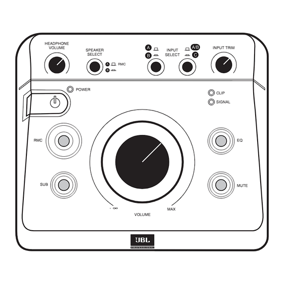
Page 10: Section 5: Features And Operation
MSC1 is powered ON. 2. POWER SWITCH - When the MSC1 is connected to an AC power source, press this button to power-on the MSC1 (The front panel buttons will illuminate in a pattern). - Page 11 INPUT SELECT Switch 1 has no effect. Note: If the INPUT SELECT Switch 2 is depressed (set to the C position), the MSC1 will always be monitoring Input C, regardless of the position of INPUT SELECT Switch 1 .
- Page 12 (see #6 above). The CLIP LED illuminates when signal is within 3 dB of the MSC1 maximum level output. It is acceptable for this LED to illuminate occasionally. If the CLIP LED illuminates...
- Page 13 Three Bass Management crossover frequencies are provided and the MSC1 ships with an 80 Hz Bass Management crossover selected and subwoofer gain set to 0 dB (no additional boost or attenuation). (See the MSC1 Control Center Software User's Guide.) Note: If your subwoofer has a crossover frequency control, the control should be set to the highest available frequency.
-
Page 14: Msc1 Rear Panel Connectors
POWER CONNECTOR – Connect the supplied 12VDC 500mA power supply here. Note that when the MSC1 is first plugged in, the front panel POWER LED will flash twice, after which the MSC1 enters stand by mode. When in stand by mode, no indicators are illuminated and audio output is not available. - Page 15 Section 5: Features and Operation Note: If the Subwoofer has Left and Right inputs, connect the MSC1 SUB "A" Output to either the Left or Right Subwoofer input. Set the Subwoofer crossover control to the highest available frequency. If the Subwoofer has a LFE (Low-Frequency Effects) input or a direct input, connect the MSC1 SUB "A"...
-
Page 16: Section 6: Installing Msc1 Control Center Software
Section 6: Installing the MSC1 Control Center Software Windows Operating System Minimum System Requirements Hard Drive: 200 MB available space RAM: 1 GB minimum CPU: Pentium(4) 1.6 GHZ or better (Duo core recommended) Netbook and ATOM processor not supported Operating System: Windows XP (SP2), Vista, Windows7 32-bit / 64-bit Audio: Accessible analog audio IN/OUT connectors of an internal soundcard or optional external audio interface, Directx9 compatible. -
Page 17: Section 7: Installing Msc1 Control Center Software
2. In the event that the installation doesn’t auto-launch, from the Start Menu, click RUN 3. Click BROWSE 4. Locate the drive containing the MSC1 Control Center Software CD-ROM. 5. Click on the file named MSC1_Application_Installer.EXE and the MSC1CC Installation Application will open. - Page 18 MSC1CC Software. 12. After you restart your computer, you can launch the MSC1 Control Center. To Uninstall the MSC1 Control Center: Launch Control Panel >Add or Remove Programs. From the “Currently Installed Programs”...
-
Page 19: Windows Operating System
Start Menu Launch Icon Start Menu Launch Icon Your MSC1 must be connected to your computer with the supplied USB cable and powered on before launching the MSC1 Control Center Software. Prior to launching the MSC1 Control Center Software, make sure your MSC1 is connected to your computer with the supplied USB cable and powered on. -
Page 20: Macintosh Operating System
Section 7: Installing the MSC1 Control Center Software Mac Operating System Minimum System Requirements Hard Drive: 200 MB available RAM: 1 GB minimum CPU: Power PC / Intel 2.0 GHZ or better (Duo core recommended) Operating System: Tiger 10.4.1.1 through Snow Leopard 10.6, Power PC/Intel. - Page 21 Section 7: Installing the MSC1 Control Center Software Mac Operating System INSTALLATION - MACINTOSH OS From CD-ROM: 1. Insert the included MSC1 Control Center CD-ROM in an available CD- ROM drive. 2. Double Click the CD icon to BROWSE. FOR INTEL MACINTOSH Computers 3.
-
Page 22: To Uninstall The Msc1 Control Center Software
Proceed to step #4 above. To Uninstall the MSC1 Control Center: Locate the MSC1 folder in the Applications folder and move it to the trash. Note: From time to time, JBL will issue software updates that enhance MSC1 Control Center functionality. -
Page 23: Launching The Msc1 Control Center Software - Macintosh Operating System
“Applications/MSC1” Folder. Desktop Your MSC1 must be connected to your computer with the supplied USB cable and powered on before launching the MSC1 Control Center Software. Prior to launching the MSC1 Control Center Software, make sure your MSC1 is connected to your computer with the supplied USB cable and powered on. -
Page 24: Section 8: Reference
It uses the power of your computer to analyze the acoustic conditions of your room RMC then compensates for low frequency inaccuracies in the listening space by having the MSC1 precisely insert filters so that signals arrive at the mix position with the intended frequency response. By making precise corrections, RMC allows you to create reliable mixes that translate to any environment. - Page 25 Three crossover settings are provided and can be set using the MSC1 Control Center software: 60 Hz, 80 Hz and 120 Hz. Also, using the software, the subwoofer level can be increased or decreased by 10 dB. Finally, during RMC calibration, the sub is automatically balanced to the speaker system.
-
Page 26: Section 9: Troubleshooting
Section 9: Troubleshooting No sound • Confirm that the power cable is connected and that the MSC1 is powered on (POWER LED is illuminated). • Confirm that a signal source is connected and producing sound and the INPUT SELECT switches are set correctly. (Note that if the INPUT SELECT switch... - Page 27 "A" SPEAKER OUTPUTS are selected.) No difference in sound when the EQ control is activated or deactivated • Using the supplied MSC1 Control Center software, confirm that an EQ setting has been made. (See MSC Control Center Software User’s Guide.) •...
- Page 28 • Speaker Delay settings To perform Factory Reset, follow this procedure: Press and hold the MSC1 front panel RMC control for 6 seconds, until the MUTE and RMC controls begin to flash. Continue to press the RMC control, and simultaneously press the MUTE control.
- Page 29 Subwoofer: 2 filters. Range: 28 Hz to 150 Hz. Gain: +0/-18 dB MSC1 Control Center Software Requirements: Use on a Macintosh Computer requires Macintosh version MSC1 Control Center Software and Macintosh Operating System. Windows OS Specs: Hard Drive: 200 MB available space • RAM: 1 GB minimum • CPU: Pentium (4) 1.6 GHZ or better ( Core™...
-
Page 30: Section 10: Specifications
Section 10: Specifications Electromagnetic Compatibility: This unit conforms to the Product Specifications noted on the Declaration of Conformity. Operation is subject to the following two conditions: 1) this device may not cause harmful interference, and 2) this device must accept any interference received, including interference that may cause undesired operation. -
Page 31: Block Diagram
Section 10: Specifications Block Diagram Controller Signal Flow Output Amplifiers 0 dB Headphone Volume -∞ Clip Signal Headphones Mute LEDs Enable Balanced 6.5mm Balanced ( -inch) Out A TRS Inputs Input A Speaker Select 24dBu Max Input Select Select A/B or C Limiter +6dB Balanced 6.5mm... -
Page 32: Section 11: Jbl Service Contact Information
Pacific Coast Time in the U.S.A. (800) 8JBLPRO (800.852.5776) www.jblproservice.com Professional Contacts, Outside the USA: Contact the JBL Professional Distributor in your area. A complete list of JBL Professional international distributors is provided at our U.S.A. website: www.jblpro.com En Dehors des Etats-Unis: Contacter votre Distributeur JBL Professional. -
Page 33: Section 12: Product Warranty Information
Northridge, California 91329 (818/893-8411). We may direct you to an authorized JBL Service Agency or ask you to send your unit to the factory for repair. Either way, you’ll need to present the original bill of sale to establish the date of purchase. - Page 34 LIMITED IN DURATION TO THE LENGTH OF THIS WARRANTY. EXCLUSION OF CERTAIN DAMAGES JBL’S LIABILITY IS LIMITED TO THE REPAIR OR REPLACEMENT, AT OUR OPTION, OF ANY DEFECTIVE PRODUCT AND SHALL NOT INCLUDE INCIDENTAL OR CONSEQUENTIAL DAMAGES OF ANY KIND. SOME STATES...
- Page 36 HARMAN JBL Professional 8500 Balboa Boulevard Northridge, CA 91329 USA www.jblpro.com Part Number: 444307-001 Rev 11.22.10...
Need help?
Do you have a question about the MSC1 and is the answer not in the manual?
Questions and answers