Table of Contents
Advertisement
Quick Links
Advertisement
Table of Contents

Subscribe to Our Youtube Channel
Related Manuals for IBM LPCI-COM-8SM


Summary of Contents for IBM LPCI-COM-8SM
-
Page 1: User Manual
10623 Roselle Street, San Diego, CA 92121 • (858) 550-9559 • FAX (858) 550-7322 contactus@accesio.com • www.accesio.com MODEL LPCI-COM-8SM LPCI-COM-4SM LPCI-COM232-8 LPCI-COM232-4 Low Profile PCI Multi-Port Serial Communications Cards USER MANUAL FILE: MLPCI-COM-8SM.B7... - Page 2 ACCES, nor the rights of others. IBM PC, PC/XT, and PC/AT are registered trademarks of the International Business Machines Corporation.
-
Page 3: Terms And Conditions
Other than the above, no other warranty, expressed or implied, shall apply to any and all such equipment furnished or sold by ACCES. Manual LPCI-COM-8SM... -
Page 4: Table Of Contents
Table A-1: Connections Between Two RS422 Devices......... 20 Table A-2: RS422 Specification Summary ............21 Figure A-1: Typical RS485 Two-Wire Multidrop Network........22 Appendix B: HVDCI D-Connector Pinout Reference ..........23 Table B-1: HVDCI D-Connector Pin Assignments..........23 Customer Comments ....................24 Manual LPCI-COM-8SM... -
Page 5: Chapter 1: Introduction
“Auto RTS (referred to by some as Auto RS485)” mode or as a “4 wire RS485 mode channel. The card is 6.60 inches long and may be installed in 3.3 or 5-volt PCI-bus slots of IBM PC or compatible computers. The card features eight independent, asynchronous serial ports, type 16788 buffered UARTs. -
Page 6: Rs485 Balanced Mode Operation
100 percent compatibility with the original IBM serial port. The system assigns the address(es). A crystal oscillator is located on the card. This oscillator permits precise selection of baud rate up to 115,200 or, by changing a jumper, up to 921,600 with the standard crystal oscillator. -
Page 7: Auto-Rts Transceiver Control
The card automatically adjusts it's timing to the baud rate of the data. (NOTE: Thanks to the automatic control feature, the card is ideal for use in Windows applications) Figure 1-1: Block Diagram (Only one serial channel shown) Manual LPCI-COM-8SM... -
Page 8: Ordering Guide
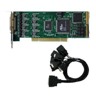
Please take the time now to ensure that no items are damaged or missing. • Eight- or four-port card with standard height mounting bracket • 6’ breakout cable to DB9M connectors • Software Master CD • Quick-Start Guide Manual LPCI-COM-8SM... -
Page 9: Chapter 2: Installation
Caution! * ESD A single static discharge can damage your card and cause premature failure! Please follow all reasonable precautions to prevent a static discharge such as grounding yourself by touching any grounded surface prior to touching the card. Manual LPCI-COM-8SM... -
Page 10: Hardware Installation
In DOS, the PCI\SOURCE directory shows the BIOS calls used to determine the address and IRQ assigned to installed PCI devices. In Windows, the Windows sample programs demonstrate querying the registry entries (created by PCIFind and NTIOPCI.SYS during boot-up) to determine this same information. Manual LPCI-COM-8SM... -
Page 11: Chapter 3: Option Selection
Also, for RS485 operation, there must be a bias on the TRX+ and TRX- lines. If the card is not to provide that bias, contact the factory technical support. Data Cable Wiring RS-485 Signal Pin Connection Ain/out+ Ain/out- 100 Ω to Ground Manual LPCI-COM-8SM... -
Page 12: Baud Rate Ranges
Interrupt = REG_DWORD 5 DosDevices = REG_SZ COM6 DosDevices = REG_SZ COM10 InterruptStatus = REG_DWORD 0xFC40 InterruptStatus = REG_DWORD 0xFC40 PortIndex = REG_DWORD 4 PortIndex = REG_DWORD 8 Indexed = REG_DWORD 0 Indexed = REG_DWORD 0 Table 3-1: WindowsNT Registry Values Manual LPCI-COM-8SM... -
Page 13: Figure 3-2: Option Selection Map
In order to select the basic mode for a channel, the M1 and M2 jumpers must be properly placed. (These jumpers are located at the end of the card away from the cable connector). Mode RS485 (2 Wire Mode) RS485 (4 Wire Mode) OUT RS422 RS232 OUT OUT Manual LPCI-COM-8SM... -
Page 14: Other Jumpers
Auto RTS function into the appropriate channel(s) of the UART. If the state of this jumper is changed, the UART will not be properly programmed until the jumper has been reread. To do this, the card must be reset. Manual LPCI-COM-8SM... -
Page 15: Chapter 4: Address Selection
PCIFind uses the Vendor ID and Device ID to search for your card, then reads the base address and IRQ. If you want to determine the base address and IRQ yourself, use the following information. The Vendor ID for the card is 494F. (ASCII for "IO") The Device ID for the card is 10E8h. Manual LPCI-COM-8SM... -
Page 16: Chapter 5: Programming
►SetupComm(), SetCommTimeouts(), GetCommState(), and SetCommState() to set and change a port’s settings. ►ReadFile() and WriteFile() for accessing a port. See the documentation for your chosen language for details. Under DOS, the process is identical to programming any 16550- or 16750-compatible UART. Manual LPCI-COM-8SM... -
Page 17: Address Map
*These are theoretical maximums based on typical conditions and good quality cables, based on the EIA 485 and EIA 422 standard for balanced differential drivers. The maximum cable length allowable for RS-232 communications is 50 feet due to single-ended line driver signaling. Table 5-1: Baud Rate Divisor Values Manual LPCI-COM-8SM... -
Page 18: Chapter 6: Connector Pin Assignments
RS485 (2 wire) requires the installation of jumpers on the card to properly connect these pins. When using the spider cable, the appropriate DB 9 connectors will have pin 1 connected to pin 3 and pin 2 is connected to pin 9. Manual LPCI-COM-8SM... -
Page 19: Chapter 7: Specifications
• I/O Connection: 68 Pin HVDCI SCSI style -Connector • Serial Ports: Eight leg breakout cable terminated with shielded male D-sub 9-pin standard IBM AT connectors compatible with RS485 specifications • Character length: 5, 6, 7, or 8 bits. •... -
Page 20: Appendix A: Application Considerations
If the differential voltage input is less than -200 mV, the receiver will provide the opposite logic state on its output. A maximum operating voltage range is from +6V to -6V allows for voltage attenuation that can occur on long transmission cables. Manual LPCI-COM-8SM... -
Page 21: Table A-2: Rs422 Specification Summary
You do not have to add a terminator resistor to your cables when you use the card. Termination resistors for the RX+ and RX- lines are provided on the card and are placed in the circuit when you install the Ch X - LD jumpers. (See the Option Selection section of this manual.) Manual LPCI-COM-8SM... -
Page 22: Figure A-1: Typical Rs485 Two-Wire Multidrop Network
This has advantages in equipment that uses mixed protocol communications. Since the slave nodes never listen to another slave's response to the master, a slave node cannot reply incorrectly. Manual LPCI-COM-8SM... -
Page 23: Appendix B: Hvdci D-Connector Pinout Reference
Pin 33 on the 68-Pin connector is Ground, common to Pin 5 on each of the DB-9 connectors associated with COM Channels A, B, C, and D. Pin 67 on the 68-Pin connector is Ground, common to Pin 5 on each of the DB-9 connectors associated with COM Channels A, B, C, and D. Manual LPCI-COM-8SM... -
Page 24: Customer Comments
If you experience any problems with this manual or just want to give us some feedback, please email us at: manuals@accesio.com. Please detail any errors you find and include your mailing address so that we can send you any manual updates. 10623 Roselle Street, San Diego CA 92121 Tel. (858)550-9559 FAX (858)550-7322 www.accesio.com Manual LPCI-COM-8SM...
Need help?
Do you have a question about the LPCI-COM-8SM and is the answer not in the manual?
Questions and answers