
Related Manuals for Generac Power Systems 37kW NG


Summary of Contents for Generac Power Systems 37kW NG
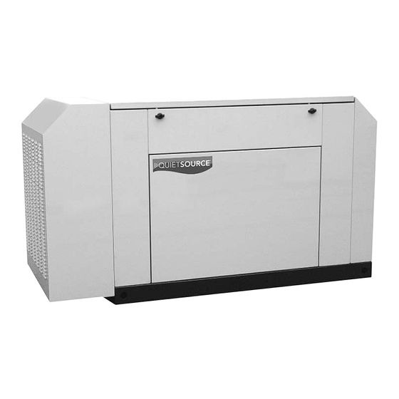
- Page 1 Owner’s Manual Liquid-cooled, Prepackaged Standby Generators Model No: 005012-0 37kW NG, 40kW LP This manual should remain with the unit. ONLY QUALIFIED ELECTRICIANS OR CONTRACTORS SHOULD ATTEMPT INSTALLATION!!
-
Page 2: Introduction
Proper maintenance and care of the generator ensures a minimum number of problems and keep operating expenses at a minimum. See the Generac Authorized Service Dealer for service aids and accessories. Operating instructions presented in this manual... -
Page 3: Table Of Contents
Section 5 — TROUBLESHOOTING ...22 Section 6 — INSTALLATION DIAGRAM ...23 Section 7 — ELECTRICAL DATA ...24 Section 8 — EXPLODED VIEWS AND PARTS LISTS ...28 Section 9 — NOTES ...43 Section 10 — WARRANTY ...Back Cover Generac ® Power Systems, Inc. -
Page 4: Important Safety Instructions
If using a procedure, work method or operating technique that Generac does not specifically recommend, ensure that it is safe for others. Also make sure the procedure, work method or operat- ing technique chosen does not render the generator unsafe. -
Page 5: Electrical Hazards
Keep the area surrounding the generator clean and free from debris. • Generac generator sets may operate using one of sev- eral types of fuels. All fuel types are potentially FLAM- MABLE and/or EXPLOSIVE and should be handled with care. -
Page 6: Section 1 - General Information
TRANSFER SWITCH This generator system is intended to be used with a Generac transfer switch. It will be available in either a NEMA 1 enclosure or a NEMA 3R enclosure. The NEMA 1 enclosure is intended for indoor use only. -
Page 7: Generator Fuel System
LED (Figure 1.6 on page 6). NOTE: HIGH COOLANT TEMPERATURE SWITCH LOW COOLANT LEVEL SWITCH Generac ® Power Systems, Inc. -
Page 8: Unpacking
If the engine fails to start after all six attempts, the start attempt is stopped and the overcrank LED turned on. Generac ® Power Systems, Inc. The engine control board continually monitors the battery voltage and turns on the low battery LED if the battery voltage falls below 11.0 VDC for one... -
Page 9: Specifications
FUEL HOSE BRASS HOSE BRASS HOSE FITTING FITTING PORT 1 PORT 2 HOUSING HOUSING PORTS PORTS NG FUEL SYSTEM (Port 1) of the demand regulator. and type for configuration. gas. Generac ® Power Systems, Inc. Port 2 PLUG LP FUEL SYSTEM... -
Page 10: Section 2 - Installation
The critical (essential) loads may need to be grouped together and wired into a sepa- rate “emergency” distribution panel. This generator can be installed in conjunction with an engineered Generac “GTS” type transfer switch, if necessary. SAE 15W-40 SAE 15W-40... -
Page 11: Generator Location
• Prevents electrical backfeed between the generator and the UTILITY power circuits. Notice that both the STANDBY and the UTILITY power supplies to the transfer switch are protected against overload by a main line circuit breaker. Generac ® Power Systems, Inc. -
Page 12: Emergency Circuit Isolation Method
Figure 2.2 – Generator Grounding Lug (typical) GENERATOR AC NEUTRAL CONNECTIONS Generac uses an UNGROUNDED AC neutral. Grounding is recommended only at the main service entrance. If the neutral wire is grounded and one of the phase loads becomes grounded, the excessive current opens the load circuit breaker or collapses the generator field. -
Page 13: Battery Installation
2.9.2 GTS-TYPE ENGINEERED TRANSFER SWITCH If the generator is to be installed with an engineered transfer switch, such as a Generac GTS-type switch, it is necessary to connect the two-wire start control system. Connect the two-wire start signal from the automatic... -
Page 14: Preparation Before Start-Up
Restrain any loose wires to keep them clear of any moving generator set components. When required, the pre-packaged standby generator can be installed with an engineered Generac “GTS” type automatic transfer switch. In this application, the GTS is responsible for utility sensing, weekly exercising, and load transferring. -
Page 15: Control Console Components
OFF before working on or around the unit. Then, place a “DO NOT OPERATE” tag on con- trol console. 3.2.2 FAULT INDICATOR LED 3.2.3 15 AMP FUSE 3.2.4 4.0 AMP INLINE FUSE NOTE: 3.2.5 SET EXERCISE TIME SWITCH Generac ® Power Systems, Inc. 13... -
Page 16: Manual Transfer And Startup
If it is set too high, it may introduce oscillations at some load. It can be set to zero (full CCW) if a small amount causes oscillations at some load. 14 Generac ® Power Systems, Inc. Figure 3.2 — Engine Governor Adjustment... -
Page 17: Section 4 - Maintenance
OVERLOAD PROTECTION FOR ENGINE DC ELECTRICAL SYSTEM If a circuit breaker opens or a fuse element melts, find the cause of the overload before resetting the circuit breaker or replacing the fuse. Generac ® Power Systems, Inc. 15... -
Page 18: Checking Fluid Levels
If coolant level is low, inspect gasket in radiator pressure cap. Replace cap, if necessary. To have pressure cap tested, contact an authorized Generac Service Dealer. Inspect cooling system and coolant recovery system for leaks. 16 Generac ®... -
Page 19: Oil Filter
SET PLUG GAP AT 1.01 mm 4.5.13 COOLANT CHANGE Every year, have an authorized service dealer drain, flush and refill the cooling system. See SPECIFICA- TIONS (Section 1.10) for cooling system recommen- dations. Generac (0.040 inch) ® Power Systems, Inc. 17... -
Page 20: Miscellaneous Maintenance
Once each year, have the generator cleaned and inspected by a Generac Authorized Service Dealer. That dealer will use dry, low pressure air to clean internal windings. Parts inside the control console should be cleaned and inspected at this time as well. -
Page 21: Scheduled Maintenance
This inspection contains some maintenance tasks which require special tools, equipment, and/or knowledge to accomplish and should be performed only by an authorized Generac Service Dealer. 3 An operational inspection of the generator set to ensure it is ready to operate and carry the load when required, and to identify any potential problem areas. - Page 22 Correct as necessary. 12. Test the engine and transfer switch safety devices. Correct and/or adjust as necessary. 20 Generac ® Power Systems, Inc. Level 2 Task Required Task Comp. to be done Comp.
- Page 23 Comp. (Date- 3 months/ (Date- Initials) Break-in Initials) Level 3 Level 4 Required Task to be done Comp. Required Semi- (Date- to be done annually Initials) Annually Generac ® Power Systems, Inc. 21 Task Comp. (Date- Initials)
-
Page 24: Section 5 - Troubleshooting
1. Replace switch. 2. Reconnect/close wire. 3. Replace board. 1. Reset to ON or CLOSED. 2. Reset and replace, if necessary. 3. Set to GENERATOR position. 4. Contact an Authorized Generac facility. 5. Auto-reset - Wait 5 min. and attempt restart. -
Page 25: Section 6 - Installation Diagram
Section 6 — Installation Diagram QUIETSOURCE™ 40kW Liquid-cooled Generators Installation Diagram — Drawing No. 0E8797 Generac ® Power Systems, Inc. 23... -
Page 26: Section 7 - Electrical Data
Section 7 - Electrical Data QUIETSOURCE™ 40kW Liquid-cooled Generators Wiring Diagram — Engine — Drawing No. 0E8115-A 24 Generac ® Power Systems, Inc. - Page 27 Section 7 - Electrical Data QUIETSOURCE™ 40kW Liquid-cooled Generators Wiring Diagram — Engine — Drawing No. 0E8115-A Generac ® Power Systems, Inc. 25...
- Page 28 Section 7 - Electrical Data QUIETSOURCE™ 40kW Liquid-cooled Generators Electrical Schematic — Engine — Drawing No. 0E8116-A 26 Generac ® Power Systems, Inc.
- Page 29 Section 7 - Electrical Data QUIETSOURCE™ 40kW Liquid-cooled Generators Electrical Schematic — Engine — Drawing No. 0E8116-A Generac ® Power Systems, Inc. 27...
-
Page 30: Section 8 - Exploded Views And Parts Lists
Section 8 - Exploded Views and Parts QUIETSOURCE™ 40kW Liquid-cooled Generators Mounting Base — Drawing No. 0E8084-A 28 Generac ® Power Systems, Inc. - Page 31 WASHER FLAT 3/8 ZINC BOOT BATTERY CABLE BATTERY POST COVWER (BLACK) BATTERY POST COVWER (RED) SCREW HHC M8-1.25 X 60 G8.8 FT NUT TOP LOCK FL M8-1.25 SPRING CLIP HOLDER .37-.62 SCREW HHTT M4-0.7 X 8 BP Generac ® Power Systems, Inc. 29...
- Page 32 Section 8 - Exploded Views and Parts QUIETSOURCE™ 40kW Liquid-cooled Generators Enclosure — Drawing No. 0E8800-B 30 Generac ® Power Systems, Inc.
- Page 33 KIT INSULATION 3.9L HSB AI ROOF PANEL 1 AI DOOR PANEL AI CORNER POST PANEL 1 AI CORNER POST PANEL 2 AI SUPPORT LH PANEL AI SUPPORT RH PANEL AI ROOF PANEL 2 WASHER SELF LOCKING DOME Generac ® Power Systems, Inc. 31...
- Page 34 Section 8 - Exploded Views and Parts QUIETSOURCE™ 40kW Liquid-cooled Generators Control Panel — Drawing No. 0E7118-H 32 Generac ® Power Systems, Inc.
- Page 35 023762 055444 030468 049939 022158 022985 038750 0A2115 0C2454 * ITEMS INCLUDED AS PART OF I/N 39 Generac QTY. DESCRIPTION BRACKET CB 221.5 X 10² DECAL WARNING ELECTRICAL SHOCK DECAL AVR COVER COVER PLATE, AVR HARNESS CNTRL PNL (NOT SHOWN) SCREW PPPH HI-LO #4-24 X 3/8 SCREW HHTT M5-0.8 X 10 BP...
- Page 36 Section 8 - Exploded Views and Parts QUIETSOURCE™ 40kW Liquid-cooled Generators Engine — Drawing No. 0E8121-G 34 Generac ® Power Systems, Inc.
- Page 37 0E9975 0F1444A 0C2454 043790 069860C 048031J 0F1444 026925 026257 Generac QTY. DESCRIPTION PLUG STD PIPE 3/8 COUNTER- SUNK WASHER FLAT 5/16-M8 ZINC SCREW HHC 5/16-18 X 1 G5 SCREW HHC M10-1.5 X 20 G8.8 WASHER LOCK M10 ASSEMBLY, D.C. ALTERNATOR PULLEY POLY-V 82 OD NUT HEX M10-1.5 G8 YEL CHR...
- Page 38 Section 8 - Exploded Views and Parts QUIETSOURCE™ 40kW Liquid-cooled Generators Radiator — Drawing No. 0E8102-E 36 Generac ® Power Systems, Inc.
- Page 39 SCREW SWAGE 10-32 X 5/16 Z/YC RADIATOR SUPPORT R/H SIDE BARBED STR 1/4NPT X 3/8 SPRING CLIP HOLDER .37-.62 SCREW HHC M10-1.5 X 20 G8.8 WASHER FLAT 3/8-M10 ZINC WASHER LOCK M10 NUT HEX M10-1.5 G8 YEL CHR Generac ® Power Systems, Inc. 37...
- Page 40 Section 8 - Exploded Views and Parts QUIETSOURCE™ 40kW Liquid-cooled Generators Fuel System — Drawing No. 0E8122-H 38 Generac ® Power Systems, Inc.
- Page 41 WASHER FLAT M5 WASHER LOCK M6-1/4 GROMMET BARBED EL 90 3/4 PLASTIC HOSE 1/2 ID SAE-30R2 FUEL/OIL PLUG STD PIPE 1/8 SOCKET HEAD ASSY THROTTLE 28MM PCV VALVE 2.5L FORD O-RING 47.625 ID X 2.38 WIDTH Generac ® Power Systems, Inc. 39...
- Page 42 Section 8 - Exploded Views and Parts QUIETSOURCE™ 40kW Liquid-cooled Generators Alternator — Drawing No. 0E5146-B 40 Generac ® Power Systems, Inc.
- Page 43 GUARD STATOR 390 SCREW HHC M6-1.0 X 25 G8.8 NUT TOP LOCK FL M6-1.0 NUT HEX M4-0.7 G8 YEL CHR WASHER FLAT #8 ZINC CONDUIT FLEX 1-1/4" (30" LG) BALL BEARING-45 MM SLIP RING -MACHINED- Generac ® Power Systems, Inc. 41...
- Page 44 BOLT U 5/16-18 X 2.25 039253 SCREW HHC M8-1.25 X 20 G8.8 022145 WASHER FLAT 5/16-M8 ZINC 022129 WASHER LOCK M8-5/16 045771 NUT HEX M8-1.25 G8 YEL CHR 42 Generac ® Power Systems, Inc. COMPARTMENT ITEM PART NO. 0C2454 052860 052891...
-
Page 45: Section 9 - Notes
Section 9 - Notes QUIETSOURCE™ 40kW Liquid-cooled Generators Generac ® Power Systems, Inc. 43... - Page 46 Section 9 - Notes QUIETSOURCE™ 40kW Liquid-cooled Generators 44 Generac ® Power Systems, Inc.
- Page 47 Section 9 - Notes QUIETSOURCE™ 40kW Liquid-cooled Generators Generac ® Power Systems, Inc. 45...
-
Page 48: Section 10 - Warranty
For a period of two years from the date of original sale, Generac Power Systems, Inc. (Generac) warrants that its Quietsource generator will be free from defects in material and workmanship for the items and period set forth below. Generac will, at its option, repair or replace any part which, upon examination, inspection and testing by Generac or an Authorized Warranty Service Dealer, is found to be defective.
Need help?
Do you have a question about the 37kW NG and is the answer not in the manual?
Questions and answers