Crown I-T4000 Operation Manual
I-tech series
Hide thumbs
Also See for I-T4000:
- Operation manual (48 pages) ,
- Brochure (6 pages) ,
- Specification sheet (2 pages)
Table of Contents
Advertisement
Operation Manual
I-Tech Series
Obtaining Other Language Versions: To obtain information in another language about the use of this product, please contact your
local Crown Distributor. If you need assistance locating your local distributor, please contact Crown at 574-294-8000.
This manual does not include all of the details of design, production, or variations of the equipment. Nor does it cover every possible
situation which may arise during installation, operation or maintenance.
The information provided in this manual was deemed accurate as of the publication date. However, updates to this information may have
occurred. To obtain the latest version of this manual, please visit the Crown website at www.crownaudio.com.
Trademark Notice: Crown, Crown Audio, IQ, IQ System, BCA, and Amcron are registered trademarks of Crown International. IQwic
and TCP/IQ are trademarks of Crown International. HiQnet is a trademark of Harman International Industries, Inc. Other trademarks are
the property of their respective owners.
Some models may be exported under the name Amcron.
®
©2005 by Crown Audio
Inc., 1718 W. Mishawaka Rd., Elkhart, Indiana 46517-9439 U.S.A. Telephone: 574-294-8000
I-T4000
I-T6000
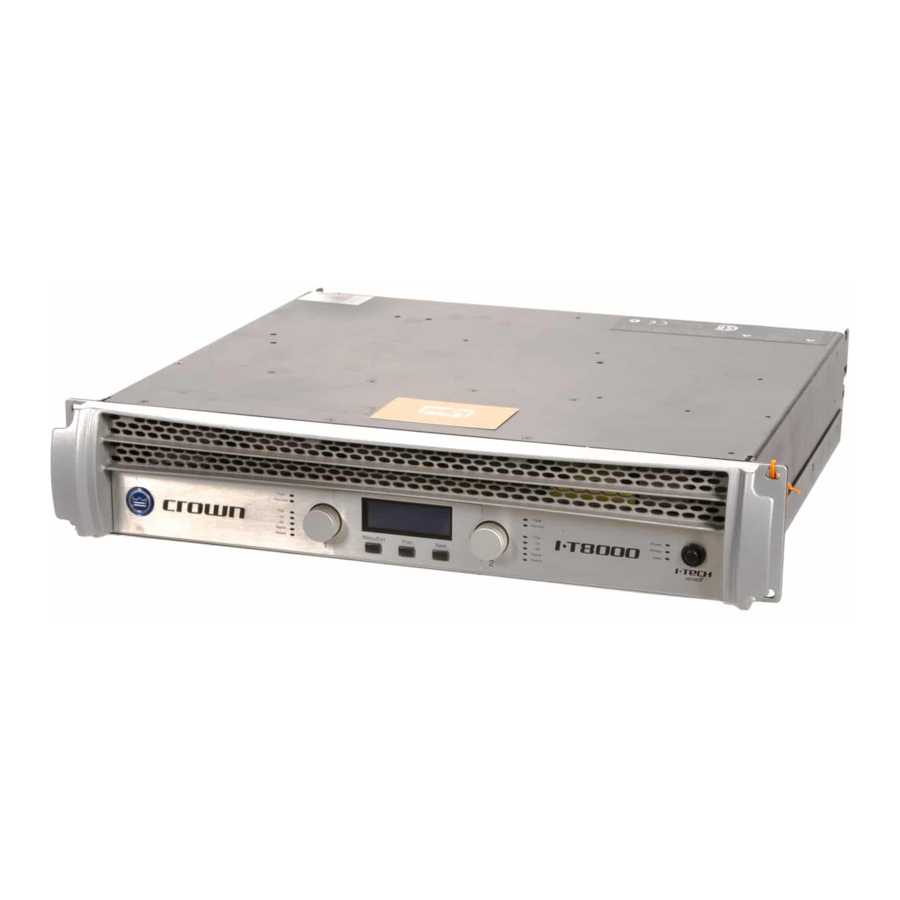
I-T8000
®
137289-6A
6/05
Advertisement
Chapters
Table of Contents

Subscribe to Our Youtube Channel
Related Manuals for Crown I-T4000


Summary of Contents for Crown I-T4000
-
Page 1: Operation Manual
To obtain the latest version of this manual, please visit the Crown website at www.crownaudio.com. Trademark Notice: Crown, Crown Audio, IQ, IQ System, BCA, and Amcron are registered trademarks of Crown International. IQwic and TCP/IQ are trademarks of Crown International. HiQnet is a trademark of Harman International Industries, Inc. Other trademarks are the property of their respective owners. -
Page 2: Important Safety Instructions
I-Tech Series Power Amplifiers Important Safety Instructions MAGNETIC FIELD Read these instructions. 15) WARNING: TO REDUCE THE RISK OF FIRE Keep these instructions. OR ELECTRIC SHOCK, DO NOT EXPOSE CAUTION! Do not locate sensitive high-gain equip- Heed all warnings. THIS APPARATUS TO RAIN OR MOISTURE. ment such as preamplifiers or tape decks directly Follow all instructions. -
Page 3: Declaration Of Conformity
CF14 9UG United Kingdom Equipment Type: Commercial Audio Power Amplifiers Family Name: I-Tech Model Names: I-T4000, I-T6000, I-T8000 EMC Standards: EN 55103-1:1997 Electromagnetic Compatibility - Product Family Standard for Audio, Video, Audio-Visual and Entertainment Lighting Control Apparatus for Professional Use, Part 1: Emissions... -
Page 4: Getting Started With I-Tech
I-Tech Series Power Amplifiers Getting Started With I-Tech Welcome! Operating your I-Tech amplifier can be as simple or advanced as you wish. Right out of the box, it works like any other amplifier with stereo loudspeaker loads. • For bridge-mono operation, see page 5. ®... -
Page 5: Quick Start Guide: Bridge-Mono Wiring
I-Tech Series Power Amplifiers Quick-Start Guide: Bridge-Mono Wiring Let’s assume that you unpacked and installed your amplifier with the proper cooling. If not, see Section 2 in this manual. We’ll also assume that you will operate the amplifier in Bridge- Mono. -
Page 6: Table Of Contents
I-Tech Series Power Amplifiers Table of Contents Important Safety Instructions ............2 4.2 Navigating the LCD Control Screen........17 Declaration of Conformity..............3 4.3 Presets ..................22 Getting Started with I-Tech ..............4 4.4 Digital-Audio Options (AES/EBU)..........22 Quick Start Guide: Stereo Wiring............4 4.5 TCP-IQ Networking ...............23 Quick Start Guide: Bridge-Mono Wiring..........5 4.6 Software-Controllable Onboard DSP ........29 Table of Contents................6... -
Page 7: Welcome
I-Tech Series Power Amplifiers 20 Hz - 20 kHz I-T4000 Power 1,800W 2-ohm Dual (per ch.) 4-ohm Dual (per ch.) 2,000W 8-ohm Dual (per ch.) 1,250W 4-ohm Bridge 3,600W Menu/Exit Prev Next 8-ohm Bridge 4,000W 20 Hz - 20 kHz Power refers to guaranteed minimum power in watts with 0.35% THD. -
Page 8: Setup
I-Tech Series Power Amplifiers 2 Setup When using an equipment rack, mount units 2.1 Unpack and Install Your CAUTION: Before you begin, make sure directly on top of each other. Close any open your amplifier is disconnected from the Amplifier spaces in rack with blank panels. -
Page 9: Connecting To Ac Mains
I-Tech Series Power Amplifiers 2 Setup 2.2 Connecting to AC Mains 2.3 Wire Inputs and Outputs WARNING: The third (ground) prong of the supplied AC power 2.3.1 Wiring basics cord connector is a required safety feature. Do not attempt to disable this ground connection by using an adapter or other •... - Page 10 I-Tech Series Power Amplifiers 2 Setup 2.3.2 Choose Input Wire and Connectors Crown recommends using pre-built or professionally wired, bal- anced line (two-conductor plus shield), 22-24 gauge cables and connectors. Use 3-pin male XLR connectors. Unbalanced line may also be used but may result in noise over long cable runs.
- Page 11 I-Tech Series Power Amplifiers 2 Setup 2.3.4 Stereo Mode Wiring Typical input and output wiring is shown in Figure 2.5. IMPORTANT: Turn off the amplifier and unplug its power cord. INPUTS: Choose one of these options: • Connect analog input wiring for both channels. •...
- Page 12 I-Tech Series Power Amplifiers 2 Setup 2.3.5 Bridge-Mono Mode Overview: Turn on the amp, enable Bridge-Mono mode using the LCD Control Screen, turn off the amp, wire it, and turn it back on. 1. Be sure that no cables are connected to the amplifier. Turn on the front-panel power switch.
-
Page 13: Operation
I-Tech Series Power Amplifiers 3 Operation 3.2 Startup Procedure 2. Use care when making connections, selecting signal sources and 3.1 Protecting Your Speakers controlling the output level. The load you save may be your own! It's wise to avoid clipping the amplifier signal. Not only does clipping When first turning on your amplifier, follow the procedures in the sound bad, it can damage high-frequency drivers. -
Page 14: Front Panel Controls And Indicators
I-Tech Series Power Amplifiers 3 Operation C. Level Controls (Encoders) clipping. The Clip Indicator also will illuminate dur- 3.4 Front Panel Controls M. Ready Indicator Speed-sensitive, 0.5 dB steps, range 0 to –100 dB. ing Thermal Level Control (TLC) limiting. and Indicators Green LED, one per channel, illuminates when the These two knobs affect the Channel-1 and... -
Page 15: Back Panel Controls, Indicators And Connectors
I-Tech Series Power Amplifiers 3 Operation OUTPUTS SECTION F. Power Cord Connector NETWORKING SECTION 3.5 Back Panel Controls, Indicators Standard 20 amp IEC inlet. Voltage range is and Connectors D. 4-Pole Speakon Output Connectors J. Preset Indicator indicated above IEC inlet. ®... -
Page 16: Advanced Operation
I-Tech Series Power Amplifiers 4 Advanced Operation 4.1 Advanced Operation Table of Contents....16 4.2 Navigating the LCD Control Screen ...... 17 4.6.3 Input Signal Level Monitor ..........29 4.2.1 Introduction................ 17 4.6.4 Output Signal Level Monitor ..........29 4.2.2 Basic Menu................ 17 4.6.5 Thermal Headroom Level Monitor ........29 4.2.3 Advanced Menu.............. -
Page 17: Navigating The Lcd Control Screen
I-Tech Series Power Amplifiers 4 Advanced Operation Some menu items require confirmation: after you request a change, 4.2 Navigating the LCD Control Screen Mute/Unmute the display might say “Press and hold.” To confirm a change, press • To mute either channel: Press and hold an Encoder knob for 4.2.1 Introduction 1 second. -
Page 18: Advanced Menu
I-Tech Series Power Amplifiers 4 Advanced Operation Presets: A preset is a group of DSP and amplifier settings for a Attenuator Link: Allows either attenuator (Encoder) to control Input Y: Press an Encoder knob to select STEREO or Input Y. You particular speaker. -
Page 19: Monitor Menu
I-Tech Series Power Amplifiers 4 Advanced Operation 4.2.4 MONITOR MENU Peak Voltage Limiter: Limits the peak output voltage to a level AES/EBU Input Trim: Sets the gain of the AES/EBU digital input that you set, either OFF or 0 to 255 volts. Press the Encoder to turn This menu lets you monitor the status of the amplifier. - Page 20 I-Tech Series Power Amplifiers 4 Advanced Operation Firmware Versions: Displays the firmware versions of the Dis- Clip Errors: This screen lets you view clip errors without using IQwic. A clip error High Limit Load Errors: This screen lets you view high limit load play and DSP.
-
Page 21: Operation Examples
I-Tech Series Power Amplifiers 4 Advanced Operation MENU TREE Attenuation - Mute - Lockout 4.2.5 Operation Examples Menu button Operation Example 1 BASIC MENU How to set the CH1 input sensitivity using the LCD Control Screen: Contrast (Prev goes to 1. -
Page 22: Presets
I-Tech Series Power Amplifiers 4 Advanced Operation 4.3.3 Downloadable Presets 4.3 Presets We will describe each type of preset in detail. Crown and JBL engineers have designed I-Tech DSP presets that are opti- 4.3.1 Introduction 4.3.2 User Presets mized for various JBL loudspeakers, such as Vertec Line Arrays. To use Your I-Tech amplifier has a wide variety of onboard Digital Signal Process- User presets are DSP presets that you set up. -
Page 23: Tcp-Iq Networking
I-Tech Series Power Amplifiers 4 Advanced Operation A TCP/ IP or IP address has two parts: the NETWORK ID and the HOST ID. The NETWORK 4.5 TCP/IQ Networking ID identifies the network, and the HOST ID identifies either the subnet and device, or just 4.5.1 The Network Wizard the device if there is no subnet. -
Page 24: Install The Wiring
I-Tech Series Power Amplifiers 4 Advanced Operation 4.5.4 Install the Wiring IMPORTANT: Please read the wiring rules below before installing the wiring. If your com- puter does not communicate with the network devices after installation and addressing, re- read this section, as well as Section 4.5.5 on TCP/IQ addressing rules. Connect each device to the network through its own cable in a Star Network. -
Page 25: Tcp/Iq Addressing Rules
I-Tech Series Power Amplifiers 4 Advanced Operation 4.5.5 TCP/IQ Addressing Rules 1. Select Settings > Control Panel > Network Connections (Figure 4.4). Set a static TCP/IP address and Subnet mask on the master computer. Document the address and mask. In the next section, you will be assigning TCP/IP addresses to the devices in your network. When you do so, be sure to follow the addressing rules below. - Page 26 I-Tech Series Power Amplifiers 4 Advanced Operation 1B. Once the Properties window opens (Figure 4.6), click on Internet Protocol (TCP/IP). 1C. We recommend that you uncheck “Obtain an IP address automatically”, and check “Use the following address.” If you decide to set an IP address manually, specify an IP address.
- Page 27 I-Tech Series Power Amplifiers 4 Advanced Operation 2B. Once TCP/IQ Utility has launched, select a single component and click on Set Address. In the Set Address window (Figure 4.10), set up a TCP/IQ address—it must be unique. Then set up the same Subnet mask for all of the components as well as the master computer.
-
Page 28: Tcp/Iq Setup
I-Tech Series Power Amplifiers 4 Advanced Operation Table 4 4.5.6 TCP/IQ Setup EXAMPLE OF AN IQ ADDRESSING WORKSHEET This example is based on a stand-alone system using switches and routers. The screen captures were done in Windows 2000; your exact configuration may vary. If your computer uses a network for other applications, please check with your Information Technology ADDRESS IQ ADDRESS... -
Page 29: Software-Controllable Onboard Dsp
I-Tech Series Power Amplifiers 4 Advanced Operation • Analog Audio Input: The audio input at the Balanced Audio Inputs 4.6.11 User and Channel Labels 4.6 Software-Controllable Onboard DSP of the I-Tech amplifier. Crown’s latest-generation Digital Signal Processing is built into the The I-Tech amplifier can store two user labels and two channel labels. -
Page 30: Input Signal Compressor/Limiter
I-Tech Series Power Amplifiers 4 Advanced Operation 4.6.14 Input Signal Compressor/Limiter Threshold: Sets the level, in absolute voltage, which the limiter will 4.6.19 Load Supervision allow from the amplifier. The range is from 12 V to 255 V An input signal compressor/limiter is available for each channel. Five The load supervision feature allows real-time monitoring of the load parameters control this feature: connected to each amplifier channel. -
Page 31: Input Signal Router
I-Tech Series Power Amplifiers 4 Advanced Operation control. When the memory backup is disabled, the amplifier stops storing 4.6.24 Noise Generator changes made to its settings. When the next power-up occurs the amplifier Each channel has an independent uncorrected noise generator that allows uses the settings that were active when the backup feature was disabled. -
Page 32: Troubleshooting
I-Tech Series Power Amplifiers 5 Troubleshooting CONDITION: Power indicator is CONDITION: Thermal indicator is off and power switch is not illu- minated. POSSIBLE REASON: POSSIBLE REASON • The amplifier is becoming too hot for safe • The amplifier has lost AC power. operation. - Page 33 I-Tech Series Power Amplifiers 5 Troubleshooting CONDITION: Data indicator not flash- CONDITION: No sound, even though ing, even though host computer IQ the amp has power. Power LED is on with- software is active. out flashing and the amp is receiving an input sig- POSSIBLE REASON: nal.
-
Page 34: Specifications
I-Tech Series Power Amplifiers 6 Specifications 6.1 Performance Minimum Guaranteed Power I-T4000 I-T6000 I-T8000 20 Hz - 20 kHz with 0.35% THD Stereo, 2 ohms (per ch.) 1800W 2500W 3500W Stereo, 4 ohms (per ch.) 2000W 3000W 4000W Stereo, 8 ohms (per ch.) - Page 35 I-Tech Series Power Amplifiers 6 Specifications Performance I-T4000 I-T6000 I-T8000 Damping Factor (8 ohms): 20 Hz to 100 Hz > 5000 > 5000 > 5000 Crosstalk (below rated power, 20 Hz to 1 kHz) > 80 dB > 80 dB >...
-
Page 36: Charts
I-Tech Series Power Amplifiers 6 Specifications 6.2 Charts Figure 6.1 Typical Frequency Response (1W) Figure 6.2 Typical Crosstalk vs. Frequency Figure 6.3 Typical Damping Factor vs. Frequency page 36 Operation Manual... -
Page 37: Ac Power Draw And Thermal Dissipation
7 AC Power Draw and Thermal Dissipation I-Tech 4000 AC Current Draw and Thermal Dissipation: Pink noise 12dB crest factor, bandwidth limited 22Hz to 22kHz. Typical line impedance used. Data based on both channels driven. I-T4000 120VAC 208VAC 230VAC Thermal Dissipation... - Page 38 I-Tech Series Power Amplifiers 7 AC Power Draw and Thermal Dissipation I-Tech 6000 AC Current Draw and Thermal Dissipation: Pink noise 12dB crest factor, bandwidth limited 22Hz to 22kHz. Typical line impedance used. Data based on both channels driven. I-T6000 120VAC 208VAC 230VAC...
- Page 39 I-Tech Series Power Amplifiers 7 AC Power Draw and Thermal Dissipation I-Tech 8000 AC Current Draw and Thermal Dissipation: Pink noise 12dB crest factor, bandwidth limited 22Hz to 22kHz. Typical line impedance used. Data based on both channels driven. I-T8000 120VAC 208VAC 230VAC...
-
Page 40: Advanced Features
I-Tech Series Power Amplifiers 8 Advanced Features quiet current waveform that is in phase with the 8.1 Protection Systems 8.2 Global Switching Power Sup- ply with PFC mains voltage waveform. PFC allows you to Your Crown amplifier provides extensive pro- reduce the size and weight of your power distri- tection and diagnostic capabilities, including Thanks to its global power supply, the I-Tech... -
Page 41: Appendix A: Tcp/Iq Network Basics
I-T4000 • Better Performance. The capacity for real-time display of meters is greatly enhanced through the use of the wide-bandwidth network. - Page 42 I-Tech Series Power Amplifiers Each IQ Component has three identifiers that are used in the TCP/IQ system: • Media Access Control (MAC) Address • Internet Protocol (IP) Address • IQ Address Let’s explain each identifier. Media Access Control (MAC) Address: This is a physical address that specifies a specific physical network component.
- Page 43 I-Tech Series Power Amplifiers The MAC address does uniquely identify each TCP/IQ component and can be used to establish the physical location of the unit. The binding of the MAC address to the IQ address through the use of the TCP/IQ Utility assures that each TCP/IQ component is physically in the right position.
-
Page 44: Appendix B: Setting Sensitivity For Best Gain Staging
I-Tech Series Power Amplifiers 9 Appendix B: Setting Sensitivity for Best Gain Staging Optimized system gain structure maximizes signal to noise within the sys- tem. Adjusting your amplifier to fit within an optimized system gain struc- ture is accomplished by properly setting both the sensitivity and attenuation controls within the amplifier. -
Page 45: Service
We recommend you form must be included with your product inside the box being notified by Crown Audio Inc. Units still in the pos- For warranty service, we will pay for ground shipping use the original pack material when returning the... -
Page 46: Warranty
I-Tech Series Power Amplifiers 11 Warranty UNITED STATES & CANADA est, insurance, closing costs, and other finance FROM ANY DEFECT IN THE NEW CROWN SUMMARY OF WARRANTY charges less a reasonable depreciation on the PRODUCT. THIS INCLUDES ANY DAMAGE TO Crown International, 1718 West Mishawaka Road, product from the date of original purchase. - Page 47 I-Tech Series Power Amplifiers 11 Warranty WORLDWIDE EXCEPT USA & CANADA SUMMARY OF WARRANTY WHAT THE WARRANTOR WILL DO DISCLAIMER OF CONSEQUENTIAL AND INCIDENTAL DAMAGES Crown International, 1718 West Mishawaka Road, We will remedy any defect, regardless of the rea- Elkhart, Indiana 46517-4095 U.S.A.
- Page 48 I-Tech Series Power Amplifiers THIS PAGE INTENTIIONALLY LEFT BLANK page 48 Operation Manual...
-
Page 49: Crown Factory Service Information Form
I-Tech Series Power Amplifiers Crown Audio Factory Service Information Shipping Address: Crown Audio Factory Service, 1718 W. Mishawaka Rd., Elkhart, IN 46517 PLEASE PRINT CLEARLY SRA #: __________________(If sending product to Crown factory service.) Model: ____________________________________________ Serial Number: _____________________ Purchase Date: _____________... - Page 50 I-Tech Series Power Amplifiers THIS PAGE INTENTIIONALLY LEFT BLANK page 50 Operation Manual...
- Page 51 I-Tech Series Power Amplifiers THIS PAGE INTENTIIONALLY LEFT BLANK Operation Manual page 51...
Need help?
Do you have a question about the I-T4000 and is the answer not in the manual?
Questions and answers