
Related Manuals for Abit KN8-SLI


Summary of Contents for Abit KN8-SLI
- Page 1 KN8 SLI AMD Athlon 64/64FX/64x2 Dual Core System Board Socket 939 User’s Manual 4200-0466-01 Rev. 1.00...
- Page 2 Copyright and Warranty Notice The information in this document is subject to change without notice and does not represent a commitment on part of the vendor, who assumes no liability or responsibility for any errors that may appear in this manual. No warranty or representation, either expressed or implied, is made with respect to the quality, accuracy or fitness for any particular part of this document.
-
Page 3: Table Of Contents
Table of Contents Chapter 1. Introduction ................1-1 1-1. Features & Specifications ................1-1 1-2. Layout Diagram ..................1-3 Chapter 2. Hardware Setup..............2-1 2-1. Install The Motherboard................2-1 2-2. Install CPU, Heatsink and Fan Assembly..........2-2 2-3. Install System Memory ................2-4 2-4. Install Graphics Card(s) ................2-6 (1). - Page 4 Install Realtek Audio Driver............B-1 Appendix C. Install Cool’n’Quiet Driver ............. C-1 Appendix D. Install USB 2.0 Driver ..............D-1 Appendix E. ABIT EQ (The Hardware Doctor Utility) ........E-1 Appendix F. FlashMenu (BIOS Update Utility) ..........F-1 Appendix G. NVRaid Floppy Disk................G-1 Appendix H.
-
Page 5: Chapter 1. Introduction
Two PCI-Express X16 slots support NVIDIA Scalable Link Interface • ™ Increase bandwidth of the PCI Express bus providing 60x the bandwidth of PCI 5. ABIT Engineered • ABIT Silent OTES II • ABIT CPU ThermalGuard ™ Technology • ABIT SoftMenu™Technology 6. - Page 6 Chapter 1 11. Internal I/O Connectors • 2x PCI-E X16 slot • 3x PCI-E X1 slots • 2x PCI slots • 1x Floppy port supports up to 2.88MB • 2x Ultra DMA 133/100/66/33 IDE connectors • 4x SATA 3G connectors •...
-
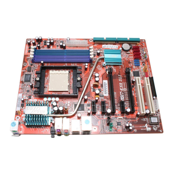
Page 7: Layout Diagram
Introduction 1-2. Layout Diagram User’s Manual... - Page 8 Chapter 1 Chapter 1 KN8 SLI KN8 SLI...
-
Page 9: Chapter 2. Hardware Setup
Hardware Setup Chapter 2. Hardware Setup Before the Installation: Turn off the power supply switch (fully turn off the +5V standby power), or disconnect the power cord before installing or unplugging any connectors or add-on cards. Failing to do so may cause the motherboard components or add-on cards to malfunction or damaged. 2-1. -
Page 10: Install Cpu, Heatsink And Fan Assembly
Chapter 2 2-2. Install CPU, Heatsink and Fan Assembly Please pay attention to the following notices before installing the CPU and heatsink/fan assembly. 1. Always use the processor with the Heatsink and Fan Assembly installed. 2. Do not touch the pins on the processor. 3. - Page 11 Hardware Setup 6. On the other side, push the retention clip straight down to lock into the plastic lug on the retention frame. 7. Turn the cam lever to lock into the retention frame. 8. Attach the four-pin power plug from the heatsink and fan assembly to the CPU FAN connector.
-
Page 12: Install System Memory
Chapter 2 2-3. Install System Memory This motherboard provides four 184-pin DDR DIMM slots for Single/Dual Channel DDR 400/333/266 memory modules with memory expansion size up to 4GB. Table 2-1. Valid Memory Configurations Bank Memory Module Total Memory Bank 0, 1 (DIMM1) 256, 512MB, 1GB 256MB ~ 1GB Bank 2, 3 (DIMM2) - Page 13 Hardware Setup To reach the performance of Dual Channel DDR, the following rules must be obeyed: • When installing TWO DIMM modules: Install DIMM modules of the same type and size for slots [DIMM1]+[DIMM2] or slots [DIMM3]+[DIMM4]. • When installing FOUR DIMM modules: Install DIMM modules of the same type and size for slots [DIMM1]+[DIMM2], and slots [DIMM3]+[DIMM4].
-
Page 14: Install Graphics Card(S)
Normal Mode: (1). 3. .Insert a PCIE graphics card into PCIEXP1 1. Locate ABIT Shadow Card in the package. slot. NOTE: Be sure to insert your ABIT Shadow Card into PCIEXP2 slot, do not switch it with the graphics card. -
Page 15: Sli Mode
Hardware Setup SLI Mode: (2). To install two SLI-ready graphics cards under SLI Mode, you will need to: • Prepare two identical NVIDIA certified, SLI-ready PCI Express x16 graphics cards (the same model from the same manufacturer). • Make sure the graphics card driver supports the NVIDIA SLI technology. Download the latest driver form NVIDIA website (www.nvidia.com). - Page 16 Chapter 2 6. Insert the SLI bracket into the bracket slot between the graphics cards. Secure the SLI bracket and the graphics cards to the chassis with screws. NOTE: The OTES SLIpstream that packed in the package is optional. Please refer to the Quick Installation Guide...
-
Page 17: Connectors, Headers And Switches
Hardware Setup 2-5. Connectors, Headers and Switches Here we will show you all of the connectors, headers and switches, and how to connect them. Please read the entire section for necessary information before attempting to finish all the hardware installation inside the computer chassis. -
Page 18: Fan Power Connectors
2-10 Chapter 2 (2). FAN Power Connectors These connectors each provide power to the cooling fans installed in your system. • CPUFAN1: CPU Fan Power Connector • SYSFAN1: System Fan Power Connector • AUXFAN1, AUXFAN2: Auxiliary Fan Power Connector WARNING: These fan connectors are not jumpers. DO NOT place jumper caps on these connectors. KN8 SLI... -
Page 19: Cmos Memory Clearing Header
Hardware Setup 2-11 (3). CMOS Memory Clearing Header This header uses a jumper cap to clear the CMOS memory. • Pin 1-2 shorted (default): Normal operation. • Pin 2-3 shorted: Clear CMOS memory. WARNING: Turn the power off first (including the +5V standby power) before clearing the CMOS memory. -
Page 20: Front Panel Switches & Indicators Headers
2-12 Chapter 2 (4). Front Panel Switches & Indicators Headers This header is used for connecting switches and LED indicators on the chassis front panel. Watch the power LED pin position and orientation. The mark “+” aligning to the pin in the figure below stands for positive polarity for the LED connection. -
Page 21: Additional Usb Port Headers
Hardware Setup 2-13 (5). Additional USB Port Headers These headers each provide 2 additional USB 2.0 ports connection through a USB cable designed for USB 2.0 specifications. Pin Assignment Pin Assignment Data0 - Data1 - Data0 + Data1 + Ground Ground User’s Manual... -
Page 22: Wake-Up Header
2-14 Chapter 2 (6). Wake-up Header These headers use a jumper cap to enable/disable the wake-up function. • PS2-PWR1: Pin 1-2 shorted (Default): Disable wake-up function support at Keyboard/Mouse port. Pin 2-3 shorted: Enable wake-up function support at Keyboard/Mouse port. •... -
Page 23: Floppy And Ide Disk Drive Connectors
Hardware Setup 2-15 (7). Floppy and IDE Disk Drive Connectors The FDC1 connector connects up to two floppy drives with a 34-wire, 2-connector floppy cable. Connect the single end at the longer length of ribbon cable to the FDC1 on the board, the two connectors on the other end to the floppy disk drives connector. -
Page 24: Serial Ata Connectors
2-16 Chapter 2 (8). Serial ATA Connectors These connectors are provided to attach one Serial ATA device at each channel via Serial ATA cable. (9). Status Indicators • LED1 (5VSB): This LED lights up when the power supply is connected with power source. •... -
Page 25: Pci Express X16 Slot
Hardware Setup 2-17 (10). PCI Express x16 Slot This slot is used to attach the next generation of graphics architecture. (11). PCI Express x1 Slots These slots are used to attach the next generation of I/O architecture. User’s Manual... -
Page 26: Front Panel Audio Connection Header
2-18 Chapter 2 (12). Front Panel Audio Connection Header This header provides the connection to audio connector at front panel. Pin Assignment Pin Assignment Audio Mic. Ground Audio Mic. Bias Speaker Out Right Speaker Out Right Channel Channel Return Speaker Out Left Speaker Out Left Channel Channel Return... -
Page 27: Internal Audio Connectors
Hardware Setup 2-19 (13). Internal Audio Connectors These connectors connect to the audio output of internal CD-ROM drive or add-on card. User’s Manual... -
Page 28: Back Panel Connectors
2-20 Chapter 2 (14). Back Panel Connectors • Mouse: Connects to PS/2 mouse. • Keyboard: Connects to PS/2 keyboard. • OPT-OUT1: This connector provides an S/PDIF-Out connection through optical fiber to digital multimedia devices. • AUDIO1: S.L./S.R. (Surround Left / Surround Right): Connects to the surround left and surround right channel in the 7.1 channel audio system. -
Page 29: Chapter 3. Bios Setup
BIOS Setup Chapter 3. BIOS Setup This motherboard provides a programmable EEPROM that you can update the BIOS utility. The BIOS (Basic Input/Output System) is a program that deals with the basic level of communication between processor and peripherals. Use the BIOS Setup program only when installing motherboard, reconfiguring system, or prompted to “Run Setup”. -
Page 30: Softmenu Setup
Chapter 3 3-1. SoftMenu Setup The SoftMenu utility is ABIT’s exclusive and ultimate solution in programming the CPU operating speed. All the parameters regarding CPU FSB speed, multiplier factor, the AGP & PCI clock, and even the CPU core voltage are all available at your fingertips. - Page 31 BIOS Setup CPU FSB Clock(MHz): This item selects the external clock frequency. Due to the specification limit of the CPU you installed, the speed you set over its standard bus speed is supported, but not guaranteed. Multiplier Factor: This item displays the multiplier factor for the CPU you installed. PCIE Clock: This item selects the PCI Express frequency.
-
Page 32: Standard Cmos Features
Chapter 3 3-2. Standard CMOS Features This section contains the basic configuration parameters of the BIOS. These parameters include date, hour, VGA card, FDD and HDD settings. Phoenix – Award WorkstationBIOS CMOS Setup Utility Standard CMOS Features Date (mm:dd:yy) Thu. Jan 1 2005 Item Help Time (hh:mm:ss) 12 : 34 : 56... - Page 33 BIOS Setup IDE Channel 1 Master/Slave, IDE Channel 2 Master/Slave, IDE Channel 3 Master, IDE Channel 4 Master, IDE Channel 5 Master, IDE Channel 6 Master: Click <Enter> key to enter its submenu: Phoenix – Award WorkstationBIOS CMOS Setup Utility IDE Channel 1 Master IDE HDD Auto-Detection Press Enter...
- Page 34 Chapter 3 Head: This item configures the number of read/write heads. Precomp: This item displays the number of cylinders at which to change the write timing. Landing Zone: This item displays the number of cylinders specified as the landing zone for the read/write heads. Sector: This item configures the number of sectors per track.
-
Page 35: Advanced Bios Features
BIOS Setup 3-3. Advanced BIOS Features Phoenix – Award WorkstationBIOS CMOS Setup Utility Advanced BIOS Features Quick Power on Self Test Enabled Item Help ► Hard Disk Boot Priority Press Enter First Boot Device Floppy Second Boot Device Hard Disk Third Boot Device CDROM Boot Other Device... - Page 36 Chapter 3 Security Option: This item determines when the system will prompt for password - every time the system boots or only when it enters the BIOS setup. [Setup]: The password is required only when accessing the BIOS Setup. [System]: The password is required each time the computer boots up. To disable security, select Set Password at main menu and then you will be asked to enter the password.
-
Page 37: Advanced Chipset Features
BIOS Setup 3-4. Advanced Chipset Features Phoenix – Award WorkstationBIOS CMOS Setup Utility Advanced Chipset Features HT Frequency AUTO Item Help ► DRAM Configuration Press Enter SSE/SSE2 Instructions Enable System BIOS Cachable Disable ↑↓:Move Enter:Select +/-/PU/PD:Value F10:Save ESC:Exit F1:General Help F5: Previous Values F6: Fail-Safe Defaults F7: Optimized Defaults... - Page 38 3-10 Chapter 3 DRAM Timing Selectable: This item selects the DRAM timing mode. When set to “By SPD”, the BIOS will read the DRAM module SPD data and automatically set to the values stored in it. Leave this item to its default “Auto” setting. DRAM Clock: This item sets the DRAM clock of your DRAM module.
- Page 39 BIOS Setup 3-11 Max. Async Latency value: This item specifies the Max Async value. Bank Interleaving: Depending on your SDRAM module structure, the 4-Way setting can offer the best performance. If you choose the wrong setting, the computer system will not run in a stable manner. For detailed information on your SDRAM module, please ask your SDRAM module manufacturer.
-
Page 40: Integrated Peripherals
3-12 Chapter 3 3-5. Integrated Peripherals Phoenix – Award WorkstationBIOS CMOS Setup Utility Integrated Peripherals ► IDE/RAID Function Press Enter Item Help Init Display First PCI Slot OnChip USB V1.1+V2.0 - USB Keyboard Support via - USB Mouse Support via OnChip Audio Controller Auto OnChip LAN Controller... -
Page 41: Ide Function Setup
BIOS Setup 3-13 IDE Function Setup: Click <Enter> key to enter its submenu: Phoenix – Award WorkstationBIOS CMOS Setup Utility IDE Fuction Setup OnChip IDE Channel 1 Enabled Item Help OnChip IDE Channel 2 Enabled IDE DMA transfer access Enabled IDE HDD Block Mode Enabled Serial-ATA 1/2... -
Page 42: Raid Config
3-14 Chapter 3 RAID Config: Click <Enter> key to enter its submenu: Phoenix – Award WorkstationBIOS CMOS Setup Utility RAID Config RAID Enable Diaabled Item Help X - IDE 1 Master RAID Disabled X - IDE 1 Slave RAID Disabled X - IDE 2 Master RAID Disabled X - IDE 2 Slave RAID... - Page 43 BIOS Setup 3-15 OnChip Audio Controller: This option enables or disables the audio controller. OnChip LAN Controller: This option enables or disables the LAN controller. Onboard LAN Boot ROM: This item allows you to use the boot ROM (instead of a disk drive) to boot-up the system and access the local area network directly.
-
Page 44: Power Management Setup
3-16 Chapter 3 3-6. Power Management Setup Phoenix – Award WorkstationBIOS CMOS Setup Utility Power Management Setup ACPI Suspend Type S3(Suspend-to-RAM) Item Help - USB Resume from S3 Disabled Power Button Function Instant-Off Wake-Up by PME# of PCI Disabled Wake-Up by OnChip LAN Enabled Wake-Up by Alarm Disabled... - Page 45 BIOS Setup 3-17 Wake-Up by Alarm: Two options are available: Disabled or Enabled. The default setting is Disabled. When set to Enabled, you can set the date and time at which the RTC (real-time clock) alarm awakens the system from Suspend mode.
-
Page 46: Pnp/Pci Configurations
3-18 Chapter 3 3-7. PnP/PCI Configurations Phoenix – Award WorkstationBIOS CMOS Setup Utility PnP/PCI Configurations Resources Controlled By Auto(ESCD) Item Help x IRQ Resources Press Enter PCI/VGA Pallete Snoop Disbaled PIRQ_0 Use IRQ No. Auto PIRQ_1 Use IRQ No. Auto PIRQ_2 Use IRQ No. -
Page 47: Irq Resources
BIOS Setup 3-19 IRQ Resources: Click <Enter> key to enter its submenu: This item sets each system interrupt to either [PCI Device] or [Reserved]. Phoenix – Award WorkstationBIOS CMOS Setup Utility PnP/PCI Configurations IRQ-3 assigned to PCI Device IRQ-4 assigned to PCI Device IRQ-5 assigned to PCI Device... -
Page 48: Pc Health Status
3-20 Chapter 3 3-8. PC Health Status You can set the warning temperature for your computer system, and you can check the fan speeds and power supply voltages of your computer system. The features are useful for monitoring all the important parameters within your computer system. - Page 49 BIOS Setup 3-21 CPU Warning Temperature: This item lets you select the temperature at which you want the system to send out a warning message to the PC speakers of when the temperature goes beyond either limit. You can select the temperatures you want.
-
Page 50: Load Fail-Safe Defaults
3-22 Chapter 3 3-9. Load Fail-Safe Defaults This option loads the BIOS default values for the most stable, minimal-performance system operations. 3-10. Load Optimized Defaults This option loads the BIOS default values that are factory settings for optimal-performance system operations. 3-11. -
Page 51: Appendix A. Install Nvidia Nforce Chipset Driver
Install nVidia nForce Chipset Driver Appendix A. Install nVidia nForce Chipset Driver NOTE: Please install this NVIDIA nForce Chipset driver first after having installed the Windows operating system. The installation procedures and screen shots in this section are based on the Windows XP operating system. - Page 52 Appendix A 6. Click [Next]. 9. Click [Next]. 7. Click [Next]. 10. Choose [Yes, I want to restart my computer now.], and click [Finish] to complete setup. 8. Click [Next]. KN8 SLI...
-
Page 53: Appendix B. Install Realtek Audio Driver
Install Realtek Audio Driver Appendix B. Install Realtek Audio Driver The installation procedures and screen shots in this section are based on Windows XP operating system. For those of other OS, please follow its on-screen instruction. Insert the Driver & Utility CD into CD-ROM drive, it should execute the installation program automatically. - Page 54 Appendix B NOTE: Click the [SPDIF] tab on the top of the control panel, and the page allows you to configure the settings for the Digital Audio input and output. There are four S/PDIF-Out options provided. • [No Output] S/PDIF-Out function is disabled and there will be no output signals.
-
Page 55: Appendix C. Install Cool'n'quiet Driver
Install Cool’n’Quiet Driver Appendix C. Install Cool’n’Quiet Driver The installation procedures and screen shots in this section are based on Windows XP operating system. For those of other OS, please follow its on-screen instruction. Insert the Driver & Utility CD into CD-ROM drive, it should execute the installation program automatically. - Page 56 Appendix C 6. After the system restarted, open the “Power Options” from the control panel and choose the power scheme “Minimal Power Management” to enable Cool ‘n’ Quiet. NOTE: For Windows 2000 or ME system, an AMD Cool ‘n’ Quiet tab will appear under “Power Options”...
-
Page 57: Appendix D. Install Usb 2.0 Driver
Install USB 2.0 Driver Appendix D. Install USB 2.0 Driver NOTE: The installation for USB 2.0 driver for Windows XP or Windows 2000 is currently available by updating the latest Service Pack from Microsoft’s web site. User’s Manual... - Page 58 Appendix D KN8 SLI...
-
Page 59: Appendix E. Abit Eq (The Hardware Doctor Utility
ABIT EQ (The Hardware Doctor Utility) Appendix E. ABIT EQ (The Hardware Doctor Utility) ABIT EQ is a self-diagnostic system for PC based on motherboards designed and manufactured by ABIT Computer Corporation. It will protect PC Hardware by monitoring critical items of Power Supply Voltage, CPU &... - Page 60 Appendix E 4. Choose [Yes, I want to restart my computer now.] and click [Finish] to complete setup. 6. This screen appears. ABIT EQ shows you the status of Voltage, Fan Speed, and Temperature readings as well. 5. Execute the ABIT EQ by entering the Windows Menu [Start] $ [All Programs] $ [ABIT] $ [ABIT EQ].
-
Page 61: Appendix F. Flashmenu (Bios Update Utility
ABIT FlashMenu is the most stable Windows-based BIOS flash available. No more worries from crashing. With one click of BIOS updating, ABIT users can flash their BIOS more easily and in less time. The installation procedures and screen shots in this section are based on the Windows XP operating system. - Page 62 Appendix F 5. Execute the FlashMenu by entering the Windows Menu [Start] $ [All Programs] $ [ABIT] $ [FlashMenu]. 6. This FlashMenu screen appears. You can easily update the BIOS from clicking [Update From File], [One Click LiveUpdate], or [LiveUpdate Step by Step] button.
-
Page 63: Appendix G. Nvraid Floppy Disk
CD to enter the installation menu. After entering the installation menu, move your curser to [ABIT Utility] tab. Click [AN8 NVRaid Floppy Disk]. The following screen appears. 1. Insert one blank floppy disk to the selected floppy drive and click [Build]. - Page 64 Appendix G KN8 SLI...
-
Page 65: Appendix H. Troubleshooting (Need Assistance
Troubleshooting (Need Assistance?) Appendix H. Troubleshooting (Need Assistance?) Q & A: Q: Do I need to clear the CMOS before I use a new motherboard to assemble my new computer system? A: Yes, we highly recommend that you clear the CMOS before installing a new motherboard. Please move the CMOS jumper from its default 1-2 position to 2-3 for a few seconds, and then back. - Page 66 Appendix H Q: How can I get a quick response to my request for technical support? A: Be sure to follow the guidelines as stated in the “Technical Support Form” section of this manual. If you have a problem during operation, in order to help our technical support personnel quickly determine the problem with your motherboard and give you the answers you need, eliminate any peripheral that is not related to the problem, and indicate it on the form.
- Page 67 Troubleshooting (Need Assistance?) Main instructions: To fill in this “Technical Support Form”, refer to the step-by-step instructions given below: . MODEL: Note the model number given in your user’s manual. Example: KN8 SLI . Motherboard model number (REV): Note the motherboard model number labeled on the motherboard as “REV:*.**”.
-
Page 68: Technical Support Form
Appendix H ( Technical Support Form ) Phone Number: ! Company Name: " Contact Person: # Fax Number: * E-mail Address: Model BIOS ID # Motherboard Model No. DRIVER REV OS/Application Hardware Name Brand Specifications IDE1 IDE2 IDE1 CD-ROM-Drive IDE2 System Memory ADD-ON CARD Problem Description:... -
Page 69: Appendix I. How To Get Technical Support
Also please make sure you have the latest drivers from your peripheral card makers! 3. Check the ABIT Technical Terms Guide and FAQ on our website. We are trying to expand and make the FAQs more helpful and information rich. Let us know if you have any suggestions. - Page 70 They should have reasonable return or refund policies. How they serve you is also a good reference for your next purchase. 6. Contacting ABIT. If you feel that you need to contact ABIT directly you can send email to the ABIT technical support department. First, please contact the support team for the branch office closest to you.
- Page 71 Unit 3, 24-26 Boulton Road, Stevenage, Herts SG1 4QX, UK Tel: 44-1438-228888 Fax: 44-1438-226333 E-mail: sales@abitcomputer.co.uk Germany and Benelux (Belgium, AMOR Computer B.V. (ABIT's European Office) Netherlands, Luxembourg), Jan van Riebeeckweg 15, 5928LG, Venlo, France, Italy, Spain, Portugal, The Netherlands Greece, Denmark, Norway, Tel: 31-77-3204428...
- Page 72 Please contact the reseller from whom you bought the product. You should be able to get RMA service there. 8. Reporting Compatibility Problems to ABIT. Because of tremendous number of email messages we receive every day, we are forced to give greater weight to certain types of messages than to others.
Need help?
Do you have a question about the KN8-SLI and is the answer not in the manual?
Questions and answers