
Related Manuals for Abit KV7-V


Summary of Contents for Abit KV7-V
- Page 1 KV7 Series (KV7, KV7-V) AMD Athlon XP System Board Socket 462 User’s Manual 4200-0380-12 Rev. 1.01...
- Page 2 Copyright and Warranty Notice The information in this document is subject to change without notice and does not represent a commitment on part of the vendor, who assumes no liability or responsibility for any errors that may appear in this manual. No warranty or representation, either expressed or implied, is made with respect to the quality, accuracy or fitness for any particular part of this document.
-
Page 3: Table Of Contents
Table of Contents Chapter 1. Introduction ................1-1 1-1. Features & Specifications ................1-1 1-2. Layout Diagram (KV7)................1-3 1-3. Layout Diagram (KV7-V)................1-4 Chapter 2. Hardware Setup ..............2-1 2-1. Install The Motherboard................2-1 2-2. Install CPU and Heatsink.................2-1 2-3. Install System Memory ................2-3 2-4. - Page 4 Appendix D. Install VIA USB 2.0 Driver .............D-1 Appendix E. Install Serial ATA RAID Driver............E-1 Appendix F. ABIT EQ (The Hardware Doctor Utility) ........F-1 Appendix G. FlashMenu (BIOS Update Utility) ..........G-1 Appendix H. Troubleshooting (Need Assistance?)..........H-1 Appendix I.
-
Page 5: Chapter 1. Introduction
Accelerated Graphics Port connector supports AGP 8X/4X Interface (0.8V/1.5V) 3. Memory • 3x 184-pin DIMM sockets • Supports 2 DIMM Un-buffered DDR 333/400 (Max. 2GB) • Supports 3 DIMM Un-buffered DDR 266 (Max. 3GB) 4. ABIT Engineered ™ • ABIT SoftMenu Technology ™ • ABIT FanEQ Technology ™... - Page 6 1x Serial port connector, 1x Parallel port connector • 1x AUDIO1 connector (Rear-Left / Rear-Right, Center/Subwoofer, S/PDIF Output, Mic-In, Line-In, Front-Left/Front-Right) (KV7) • 1x AUDIO2 connector (Mic-In, Line-In, Line-Out) (KV7-V) • 4x USB 2.0, 1x RJ-45 LAN Connector 10. Miscellaneous •...
-
Page 7: Layout Diagram (Kv7)
Introduction 1-2. Layout Diagram (KV7) User’s Manual... -
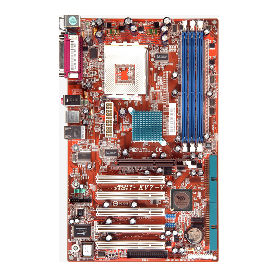
Page 8: Layout Diagram (Kv7-V)
Chapter 1 1-3. Layout Diagram (KV7-V) KV7 Series... -
Page 9: Chapter 2. Hardware Setup
Hardware Setup Chapter 2. Hardware Setup Before the Installation: Turn off the power supply switch (fully turn off the +5V standby power), or disconnect the power cord before installing or unplugging any connectors or add-on cards. Failing to do so may cause the motherboard components or add-on cards to malfunction or damaged. 2-1. - Page 10 Chapter 2 This motherboard provides a ZIF (Zero Insertion Force) Socket 462 to install AMD Socket A CPU. The CPU you bought should have a kit of heatsink and cooling fan along with. If that’s not the case, buy one specially designed for Socket A. Please refer to the figure shown here to install CPU and heatsink.
-
Page 11: Install System Memory
Hardware Setup 2-3. Install System Memory This motherboard provides 3 184-pin DDR DIMM sites for memory expansion available from minimum 128MB to maximum 3GB. Table 2-1. Valid Memory Configurations Bank Memory Module Total Memory Bank 0, 1 (DIMM1) 128, 256, 512MB, 1GB 128MB ~ 1GB Bank 2, 3 (DIMM2) 128, 256, 512MB, 1GB... -
Page 12: Connectors, Headers And Switches
Chapter 2 2-4. Connectors, Headers and Switches Here we will show you all of the connectors, headers and switches, and how to connect them. Please read the entire section for necessary information before attempting to finish all the hardware installation inside the computer chassis. -
Page 13: Fan Connectors
CPU fan. • CPUFAN1: CPU Fan • NBFAN1: Chipset Fan • SYSFAN1: System Fan • AUXFAN1, AUXFAN2: Auxiliary Fan WARNING: These fan connectors are not jumpers. DO NOT place jumper caps on these connectors. KV7: KV7-V: User’s Manual... -
Page 14: Cmos Memory Clearing Header
Chapter 2 (3). CMOS Memory Clearing Header This header uses a jumper cap to clear the CMOS memory. • Pin 1-2 shorted (default): Normal operation. • Pin 2-3 shorted: Clear CMOS memory. WARNING: Turn the power off first (including the +5V standby power) before clearing the CMOS memory. -
Page 15: S2K Mode Select Header (For Kv7 Only)
Hardware Setup S2K Mode Select Header (For KV7 only) (4). This header uses a jumper to select the S2K mode. Short pin-2 and pin-3 for “Strapping from Hardware” to allow the CPU hardware controls the timing of S2K bus for a better system flexibility. The default setting is pin-1 and pin-2 shorted for “Strapping from boot ROM”... -
Page 16: Wake-Up Header
Chapter 2 (5). Wake-up Header These headers use a jumper cap to enable/disable the wake-up function. • PS2-PWR1: Pin 1-2 shorted (default): Disable wake-up function support at Keyboard/Mouse port. Pin 2-3 shorted: Enable wake-up function support at Keyboard/Mouse port • USB-PWR1: Pin 1-2 shorted (default): Disable wake-up function support at USB1 port. -
Page 17: Front Panel Switches & Indicators Headers
Hardware Setup (6). Front Panel Switches & Indicators Headers This header is used for connecting switches and LED indicators on the chassis front panel. Watch the power LED pin position and orientation. The mark “+” align to the pin in the figure below stands for positive polarity for the LED connection. -
Page 18: Additional Usb Port Headers
2-10 Chapter 2 (7). Additional USB Port Headers These headers each provide 2 additional USB 2.0 ports connection through an USB cable designed for USB 2.0 specifications. Pin Assignment Pin Assignment Data0 - Data1 - Data0 + Data1 + Ground Ground KV7 Series... -
Page 19: Front Panel Audio Connection Header
Hardware Setup 2-11 (8). Front Panel Audio Connection Header This header provides the connection to audio connector at front panel. • To use the audio connector at front panel, remove all the jumpers on this header, and then connect to front panel by the extenson cable provided with the chassis. •... - Page 20 2-12 Chapter 2 KV7-V: Pin Assignment Pin Assignment Audio Mic. Ground Audio Mic. Bias Speaker Out Right Speaker Out Right Channel Channel Return Speaker Out Left Speaker Out Left Channel Channel Return KV7 Series...
-
Page 21: Internal Audio Connectors
Hardware Setup 2-13 (9). Internal Audio Connectors These connectors connect to the audio output of internal CD-ROM drive or add-on card. (10). Accelerated Graphics Port Slot This slot supports an optional AGP graphics card up to AGP 8X mode. Please refer to our Web site for more information on graphics cards. -
Page 22: Floppy Disk Drive Connector
2-14 Chapter 2 (11). Floppy Disk Drive Connector This connector supports two standard floppy disk drives via a 34-pin 34-conductor ribbon cable. Connecting the Floppy Disk Drive Cable: 1. Install one end of the ribbon cable into the FDC1 connector. The colored edge of the ribbon cable should be aligned with pin-1 of FDC1 connector. -
Page 23: Ide Connectors
Hardware Setup 2-15 (12). IDE Connectors This motherboard provides two IDE ports to connect up to four IDE drives at Ultra ATA/100 mode by Ultra ATA/66 ribbon cables. Each cable has 40-pin 80-conductor and three connectors, providing two hard drives connection with motherboard. Connect the single end (blue connector) at the longer length of ribbon cable to the IDE port on motherboard, and the other two ends (gray and black connector) at the shorter length of the ribbon cable to the connectors on hard drives. -
Page 24: Serial Ata Connectors
2-16 Chapter 2 (13). Serial ATA Connectors These connectors are provided to attach one Serial ATA device at each channel via Serial ATA cable. A RAID 0 or RAID 1 array is also available by software configuration. To enable the SATA1 and SATA2 controller, the item “OnChip SATA Device” must be kept enabled (default setting) in the BIOS menu of “OnChip IDE Device”. -
Page 25: Back Panel Connectors
Hardware Setup 2-17 (14). Back Panel Connectors KV7: KV7-V: • Mouse: Connects to PS/2 mouse. • Keyboard: Connects to PS/2 keyboard. • LPT1: Connects to printer or other devices that support this communication protocol. • COM1: Connects to external modem, mouse or other devices that support this communication protocol. - Page 26 2-18 Chapter 2 • AUDIO2: (KV7-V) Mic-In: Connects to the plug from external microphone. Line-In: Connects to the line out from external audio sources. Line-Out: Connects to the front left and front right channel in the 5.1-channel or regular 2-channel audio system.
-
Page 27: Chapter 3. Bios Setup
BIOS Setup Chapter 3. BIOS Setup This motherboard provides a programmable EEPROM that you can update the BIOS utility. The BIOS (Basic Input/Output System) is a program that deals with the basic level of communication between processor and peripherals. Use the BIOS Setup program only when installing motherboard, reconfiguring system, or prompted to “Run Setup”. -
Page 28: Softmenu Setup
Chapter 3 3-1. SoftMenu Setup The SoftMenu utility is ABIT’s exclusive and ultimate solution in programming the CPU operating speed. All the parameters regarding CPU FSB speed, multiplier factor, the AGP & PCI clock, and even the CPU core voltage are all available at your fingertips. - Page 29 BIOS Setup NOTE: Some processors might have this multiplier factor locked, so there is no way to choose a higher multiplier factor. Power Supply: This option allows you to switch between CPU default and user-defined voltages. Leave this setting to default unless the current CPU type and voltage setting cannot be detected or is not correct.
-
Page 30: Standard Cmos Features
Chapter 3 3-2. Standard CMOS Features This section contains the basic configuration parameters of the BIOS. These parameters include date, hour, VGA card, FDD and HDD settings. Date (mm:dd:yy): This item sets the date you specify (usually the current date) in the format of [Month], [Date], and [Year]. Time (hh:mm:ss): This item sets the time you specify (usually the current time) in the format of [Hour], [Minute], and [Second]. - Page 31 BIOS Setup IDE Primary Master / Slave and IDE Secondary Master / Slave: When set to [Auto], the BIOS will automatically check what kind of IDE drive you are using. If you want to define your own drive by yourself, set it to [Manual] and make sure you fully understand the meaning of the parameters.
- Page 32 Chapter 3 [CGA 40]: (Color Graphics Adapter) Power up in 40-column mode. [CGA 80]: (Color Graphics Adapter) Power up in 80-column mode. [Mono]: (Monochrome adapter) Includes high-resolution monochrome adapters. Halt On: This item determines whether the system stops if an error is detected during system boot-up. [All Errors]: The system-boot will stop whenever the BIOS detect a non-fatal error.
-
Page 33: Advanced Bios Features
BIOS Setup 3-3. Advanced BIOS Features Hard Disk Boot Priority: This item selects the hard disks booting priority. By pressing <Enter> key, you can enter its submenu where the hard disks detected can be selected for the booting sequence to boot up system. This item functions only when there is the option of [Hard Disk] in any one of the First/Second/Third Boot Device items. - Page 34 Chapter 3 Boot Up NumLock Status: This item determines the default state of the numeric keypad at system booting up. [On]: The numeric keypad functions as number keys. [Off]: The numeric keypad functions as arrow keys. Typematic Rate Setting: This item allows you to adjust the keystroke repeat rate. When set to Enabled, you can set the two keyboard typematic controls that follow (Typematic Rate and Typematic Rate Delay).
-
Page 35: Advanced Chipset Features
BIOS Setup Report No FDD For OS: When set to [Enabled], this item allows you to run some older operating system without floppy disk drive. Leave this item to its default setting. Delay IDE Initial (Secs): This item allows the BIOS to support some old or special IDE devices by prolonging this delay time. A larger value will give more delay time to the device for which to initialize and to prepare for activation. - Page 36 3-10 Chapter 3 Current FSB Frequency: This item will show you the current system front side bus speed. Current DRAM Frequency: This item will show you the current DRAM bus speed. DRAM Clock: This item sets the DRAM clock of your DRAM module. The system may be unstable or unable to boot up if your DRAM module does not support the clock you set.
- Page 37 BIOS Setup 3-11 it to 2T Command for system compatibility or to 1T Command for system performance. Write Recovery Time: Two options are available: 2T or 3T. The default setting is 3T. This is the period between two write times. DDR400 tWTR timing control Two options are available: 1T or 2T.
- Page 38 3-12 Chapter 3 AGP Aperture Size: This option specifies the amount of system memory that can be used by the AGP device. The aperture is a portion of the PCI memory address range dedicated for graphics memory address space. AGP Data Transfer Rate: This item selects the data transfer rate of AGP device.
- Page 39 BIOS Setup 3-13 Back to Advanced Chipset Features Setup Menu: CPU & PCI Bus Control: Click <Enter> key to enter its submenu: PCI Master 0 WS Write: Two options are available: Enabled or Disabled. The default setting is Enabled. When Enabled, writes to the PCI bus are executed with zero wait state (immediately) when PCI bus is ready to receive data.
-
Page 40: Integrated Peripherals
3-14 Chapter 3 3-5. Integrated Peripherals OnChip IDE Device: Click <Enter> key to enter its submenu: IDE Prefetch Mode: Two options are available: Disabled or Enabled. The default setting is Enabled. The onboard IDE drive interfaces supports IDE prefetching for faster drive accesses. If you install a primary and/or secondary add-in IDE interface, set this field to Disabled if the interface does not support prefetching. - Page 41 BIOS Setup 3-15 [Auto]: The BIOS will select the best available mode after checking your disk drive. [Mode 0-4]: You can select a mode that matches your disk drive’s timing. Do not use the wrong setting or you will have drive errors. Master/Slave Drive Ultra DMA This item allows you to set the Ultra DMA in use.
- Page 42 3-16 Chapter 3 USB Mouse Support Via: This item allows you to select [BIOS] for using USB mouse in DOS environment, or [OS] in OS environment. USB 2.0 Controller: This option enables or disables the USB 2.0 controller. Back to Integrated Peripherals Setup Menu: SuperIO Device: Click <Enter>...
-
Page 43: Power Management Setup
BIOS Setup 3-17 Onboard FDD Controller: Two options are available: Enabled and Disabled. The default setting is Enabled. You can enable or disable the onboard FDD controller. 3-6. Power Management Setup ACPI Suspend Type: This item selects the type of Suspend mode. [S1(POS)]: Enables the Power On Suspend function. - Page 44 3-18 Chapter 3 [Power Off]: When power returns after an AC power failure, the system’s power remains off. You must press the Power button to power-on the system. [Power On]: When power returns after an AC power failure, the system’s power will be powered on automatically.
- Page 45 BIOS Setup 3-19 PS2MS Wakeup: This item controls the PS2 mouse to wake up the system that has been powered down. Resume by OnChip USB: Two options are available: Disabled or Enabled. The default setting is Disabled. When set to Enabled, any event affecting from onchip USB will awaken a system that has powered down.
- Page 46 3-20 Chapter 3 IRQ Activity Monitroing: Click <Enter> key to enter its submenu: All Interrupt Event: Two items available: Off or Manual. The default setting is Manual. When you set this item to Manual, the following IRQ events will be available for adjustment. When set to Disabled, activity will neither prevent the system from going into a power management mode nor awaken it.
-
Page 47: Pnp/Pci Configurations
BIOS Setup 3-21 3-7. PnP/PCI Configurations Force Update ESCD: If you want to clear ESCD data next time you boot up, and ask the BIOS to reset the settings for the Plug & Play ISA Card and the PCI Card, select Enabled. But the next time you boot up, this option will automatically be set as Disabled. - Page 48 3-22 Chapter 3 Back to PnP/PCI Configurations Setup Menu: PCI/VGA Palette Snoop: This item determines whether the MPEG ISA/VESA VGA cards can work with PCI/VGA or not. [Enabled]: MPEG ISA/VESA VGA cards work with PCI/VGA. [Disabled]: MPEG ISA/VESA VGA cards do not work with PCI/VGA. Allocate IRQ To Video: This item assigns an IRQ for the VGA card installed.
-
Page 49: Pc Health Status
BIOS Setup 3-23 3-8. PC Health Status CPU Shutdown Temperature: This item sets the temperature that would shutdown the system automatically in order to prevent system overheats. CPU Warning Temperature: This item selects the CPU’s warning temperature limit. Once the system has detected that the CPU’s temperature exceeded the limit, warning beeps will sound. -
Page 50: Load Fail-Safe Defaults
3-24 Chapter 3 All Voltages, Fans Speed and Thermal Monitoring: These unchangeable items list the current status of the CPU and environment temperatures, fan speeds, and system power voltage. NOTE: The hardware monitoring features for temperatures, fans and voltages will occupy the I/O address from 294H to 297H. -
Page 51: Appendix A. Install Via 4-In-1 Driver
Install VIA 4-in-1 Driver Appendix A. Install VIA 4-in-1 Driver NOTE: Please install this VIA 4-in-1 driver first after having installed the Windows operating system. The installation procedures and screen shots in this section are based on Windows XP operating system. - Page 52 Appendix A Click [Next]. 7. Choose [Yes, I want to restart my computer now.], and click [OK] to complete setup. KV7 Series...
-
Page 53: Appendix B. Install Audio Driver
Install Audio Driver Appendix B. Install Audio Driver KV7: The installation procedures and screen shots in this section are based on Windows 2000 operating system. For those of other OS, please follow its on-screen instruction. Insert the Driver & Utility CD into CD-ROM drive, it should execute the installation program automatically. - Page 54 Appendix B KV7-V: The installation procedures and screen shots in this section are based on Windows XP operating system. For those of other OS, please follow its on-screen instruction. Insert the Driver & Utility CD into CD-ROM drive, it should execute the installation program automatically.
-
Page 55: Appendix C. Install Lan Driver
Install LAN Driver Appendix C. Install LAN Driver The installation procedures and screen shots in this section are based on Windows XP operating system. For those of other OS, please follow its on-screen instruction. Insert the Driver & Utility CD into CD-ROM drive, it should execute the installation program automatically. - Page 56 Appendix C Appendix C KV7 Series KV7 Series...
-
Page 57: Appendix D. Install Via Usb 2.0 Driver
Install VIA USB 2.0 Driver Appendix D. Install VIA USB 2.0 Driver NOTE: This VIA USB 2.0 driver package requires Windows XP SP1 (Service Pack 1), Windows 2000 SP4, or system upgrade through Windows Update. The installation procedures and screen shots in this section are based on Windows XP operating system. - Page 58 Appendix D Appendix D KV7 Series KV7 Series...
-
Page 59: Appendix E. Install Serial Ata Raid Driver
Install Serial ATA RAID Driver Appendix E. Install Serial ATA RAID Driver The installation procedures and screen shots in this section are based on Windows XP operating system. For those of other OS, please follow its on-screen instruction. Insert the Driver & Utility CD into CD-ROM drive, it should execute the installation program automatically. - Page 60 Appendix E 6. Choose [Yes, I want to restart my computer now.], and click [Finish] to complete setup. KV7 Series...
-
Page 61: Appendix F. Abit Eq (The Hardware Doctor Utility
ABIT EQ (The Hardware Doctor Utility) Appendix F. ABIT EQ (The Hardware Doctor Utility) The installation procedures and screen shots in this section are based on Windows XP operating system. For those of other OS, please follow its on-screen instruction. - Page 62 Appendix F 6. This screen appears. ABIT EQ shows you the status of Voltage, Fan Speed, and Temperature readings as well. (The item names in this screen shot are for reference only, may not be exactly the same as what you see on your monitor.)
-
Page 63: Appendix G. Flashmenu (Bios Update Utility
If not, double-click the execution file at the main directory of this CD to enter the installation menu. After entering the installation menu, move your curser to [ABIT Utility] tab. Click [FlashMenu]. The following screen appears. Click [Next]. 1. Click [Next]. - Page 64 Appendix G Click [OK]. 7. This FlashMenu screen appears. You can easily update the BIOS from clicking [Update From File], [One Click LiveUpdate], or [LiveUpdate Step by Step] button. KV7 Series...
-
Page 65: Appendix H. Troubleshooting (Need Assistance
Troubleshooting (Need Assistance?) Appendix H. Troubleshooting (Need Assistance?) Q & A: Q: Do I need to clear the CMOS before I use a new motherboard to assemble my new computer system? A: Yes, we highly recommend that you clear the CMOS before installing a new motherboard. Please move the CMOS jumper from its default 1-2 position to 2-3 for a few seconds, and then back. - Page 66 Appendix H Q: How can I get a quick response to my request for technical support? A: Be sure to follow the guidelines as stated in the “Technical Support Form” section of this manual. If you have a problem during operation, in order to help our technical support personnel quickly determine the problem with your motherboard and give you the answers you need, before filling in the technical support form, eliminate any peripheral that is not related to the problem, and indicate it on the form.
- Page 67 To fill in this “Technical Support Form”, refer to the step-by-step instructions given below: . MODEL: Note the model number given in your user’s manual. Example: KV7, KV7-V . Motherboard model number (REV): Note the motherboard model number labeled on the motherboard as “REV:*.**”.
-
Page 68: Technical Support Form
Appendix H Technical Support Form Company Name: Phone Number: Contact Person: Fax Number: E-mail Address: Model BIOS ID # Motherboard Model No. DRIVER REV OS/Application Hardware Name Brand Specifications IDE1 IDE2 IDE1 CD-ROM-Drive IDE2 System Memory ADD-ON CARD Problem Description: KV7 Series... -
Page 69: Appendix I. How To Get Technical Support
Also please make sure you have the latest drivers from your peripheral cards makers! 3. Check the ABIT Technical Terms Guide and FAQ on our Website. We are trying to expand and make the FAQs more helpful and information rich. Let us know if you have any suggestions. - Page 70 They should have reasonable return or refund policies. How they serve you is also a good reference for your next purchase. 6. Contacting ABIT. If you feel that you need to contact ABIT directly you can send email to the ABIT technical support department. First, please contact the support team for the branch office closest to you.
- Page 71 Unit 3, 24-26 Boulton Road, Stevenage, Herts SG1 4QX, UK Tel: 44-1438-228888 Fax: 44-1438-226333 E-mail: sales@abitcomputer.co.uk Germany and Benelux (Belgium, AMOR Computer B.V. (ABIT's European Office) Jan van Riebeeckweg 15, 5928LG, Venlo, Netherlands, Luxembourg), The Netherlands France, Italy, Spain, Portugal, Greece, Denmark, Norway,...
- Page 72 Marketing: market@abit.com.tw Web Site: http://www.abit.com.tw 8. Reporting Compatibility Problems to ABIT. Because of tremendous number of email messages we receive every day, we are forced to give greater weight to certain types of messages than to others. For this reason, any compatibility problem that is reported to us, giving detailed system configuration information and error symptoms will receive the highest priority.
Need help?
Do you have a question about the KV7-V and is the answer not in the manual?
Questions and answers