Table of Contents
Advertisement
KN9 SLI
KN9 Ultra
KN9S
Motherboard
AMD Socket AM2
User's Manual
About this Manual:
This user's manual contains all the information you may
need for setting up this motherboard. To read the user's
manual of PDF format (readable by
the "Driver & Utility CD" into the CD-ROM drive in your
system. The auto-run screen will appear, click the
"Manual" tab to enter its submenu. If not, browse the
root directory of the CD-ROM via the File Manager, and
double click the "AUTORUN" file.
Adobe
Reader), place
AMD Socket AM2
ATX Motherboard
NVIDIA Chipset:
MCP55P/MCP55Ultra/MCP55S
2GHz HT
Dual DDR2 800 DIMM Slots
NVIDIA SLI Technology
Dual PCI-E X16 Slots
Dual GbE LAN
IEEE 1394a
6x SATA 3Gb/s with
RAID 0/1/0+1/5/JBOD
ABIT Silent OTES™ Technology
7.1 Channel HD Audio
* See the "Features & Specifications" of each model in
this manual for details.
Advertisement
Table of Contents

Related Manuals for Abit KN9 SLI


Summary of Contents for Abit KN9 SLI
-
Page 1: Amd Socket Am2
6x SATA 3Gb/s with RAID 0/1/0+1/5/JBOD About this Manual: This user’s manual contains all the information you may ABIT Silent OTES™ Technology need for setting up this motherboard. To read the user’s manual of PDF format (readable by Adobe Reader), place the “Driver &... - Page 2 KN9 SLI, KN9 Ultra, KN9S User’s Manual English, 1 Edition May, 2006 Copyright and Warranty Notice The information in this document is subject to change without notice and does not represent a commitment on part of the vendor, who assumes no liability or responsibility for any errors that may appear in this manual.
-
Page 3: Table Of Contents
2.6.8 PCI Add-on Slots ............... 2-21 2.7 Onboard Status Display .............. 2-22 2.7.1 Power Source Indicators ............ 2-22 2.8 Connecting I/O Devices.............. 2-23 3. BIOS Setup............... 3-1 3.1 SoftMenu Setup ................3-2 3.2 Standard CMOS Features..............3-2 KN9 SLI, KN9 Ultra, KN9S... - Page 4 3.13 Exit Without Saving..............3-6 4. Driver & Utility CD............4-1 5. Appendix ................5-1 5.1 Troubleshooting (How to Get Technical Support?) ......5-1 5.1.1 Q & A .................5-1 5.1.2 Technical Support Form ............5-4 5.1.3 UNIVERSAL ABIT Contact Information ........5-5 KN9 SLI, KN9 Ultra, KN9S...
-
Page 5: Introduction
• Two PCI-Express X16 slots support NVIDIA Scalable Link Interface SATA 3Gb/s RAID • Supports 6 ports NV SATA 3Gb/s RAID 0/1/0+1/5/JBOD (For model “KN9 SLI” and “KN9 Ultra” only) • Supports 4 ports NV SATA 3Gb/s RAID 0/1/0+1/JBOD (For model “KN9S” only) GbE LAN ®... - Page 6 • 1x UDMA 133/100/66/33 connector • 4x SATA (SATA1 ~ SATA4) connectors (For model “KN9S” only) • 6x SATA (SATA1 ~ SATA6) connectors (For model “KN9 SLI” and “KN9 Ultra” only) • 3x USB 2.0 headers • 2x IEEE1394a headers (For model “KN9 SLI” and “KN9 Ultra” only) Rear Panel I/O ™...
-
Page 7: Motherboard Layout
1.2 Motherboard Layout 1.2.1 KN9 SLI KN9 SLI, KN9 Ultra, KN9S... -
Page 8: Kn9 Ultra
1.2.2 KN9 Ultra KN9 SLI, KN9 Ultra, KN9S... -
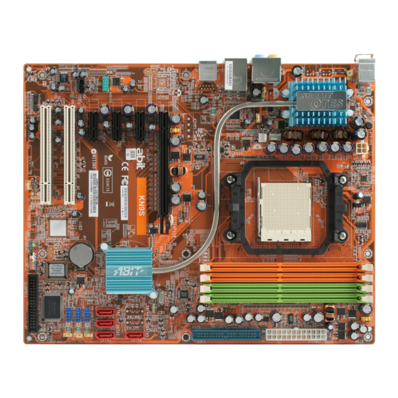
Page 9: Kn9S
1.2.3 KN9S KN9 SLI, KN9 Ultra, KN9S... - Page 10 KN9 SLI, KN9 Ultra, KN9S...
-
Page 11: Hardware Setup
After doing this to all the slots, you can slide the board into position aligned with slots. After the board has been positioned, check to make sure everything is OK before putting the chassis back on. KN9 SLI, KN9 Ultra, KN9S... -
Page 12: Checking Jumper Settings
(reserved for future use) will leave it at OPEN position. SHORT OPEN OPEN For 3-pin jumper, pin 1~2 or pin 2~3 can be shorted by plugging the jumper cap in. Pin 1~2 SHORT Pin 2~3 SHORT KN9 SLI, KN9 Ultra, KN9S... -
Page 13: Cmos Memory Clearing Header And Backup Battery
4. For incorrect CPU ratio/clock settings in the BIOS, press <Del> key to enter the BIOS setup menu right after powering on system. 5. Set the CPU operating speed back to its default or an appropriate value. 6. Save and exit the BIOS setup menu. KN9 SLI, KN9 Ultra, KN9S... - Page 14 ※ Danger of explosion may arise if the battery is incorrectly renewed. ※ Renew only with the same or equivalent type recommended by the battery manufacturer. ※ Dispose of used batteries according to the battery manufacturer’s instructions. KN9 SLI, KN9 Ultra, KN9S...
-
Page 15: Wake-Up Headers
Pin 1-2 shorted: Disable wake-up function support at FP-USB2 port. Pin 2-3 shorted (Default): Enable wake-up function support at FP-USB2 port. • FP-PWR3: Pin 1-2 shorted: Disable wake-up function support at FP-USB3 port. Pin 2-3 shorted (Default): Enable wake-up function support at FP-USB3 port. KN9 SLI, KN9 Ultra, KN9S... -
Page 16: Connecting Chassis Components
This connector supplies power to CPU. The system will not start without connecting power to this one. Auxiliary 12V Power Connector: This connector provides an auxiliary power source for devices added on PCI Express slots. KN9 SLI, KN9 Ultra, KN9S... -
Page 17: Front Panel Switches & Indicators Headers
Connects to the Suspend LED cable (if there is one) of chassis front panel. • PWR (Pin 6, 8): Connects to the Power Switch cable of chassis front panel. • PLED (Pin 16, 18, 20): Connects to the Power LED cable of chassis front panel. KN9 SLI, KN9 Ultra, KN9S... -
Page 18: Fan Power Connectors
These connectors each provide power to the cooling fans installed in your system. • CPUFAN1: CPU Fan Power Connector • SYSFAN1: System Fan Power Connector • AUXFAN1~2: Auxiliary Fan Power Connector ※ These fan connectors are not jumpers. DO NOT place jumper caps on these connectors. KN9 SLI, KN9 Ultra, KN9S... -
Page 19: Installing Hardware
3. The heatsink for CPU may have thermal interface material attached bottom. If not, applying a few squeeze of thermal paste to the CPU die will help to increase the contact. KN9 SLI, KN9 Ultra, KN9S... - Page 20 ※ A higher fan speed will be helpful for better airflow and heat-dissipation. Nevertheless, stay alert to touch any heatsink since the high temperature generated by the working system is still possible. 2-10 KN9 SLI, KN9 Ultra, KN9S...
-
Page 21: Ddr2 Memory Slots
[DIMM3] and [DIMM4] are made of another same color. Usually there is no hardware or BIOS setup requires after adding or removing memory modules, but you will have to clear the CMOS memory first if any memory module related problem occurs. KN9 SLI, KN9 Ultra, KN9S 2-11... - Page 22 DIMM module. ※ Static electricity can damage the electronic components of the computer or optional boards. Before starting these procedures, ensure that you are discharged of static electricity by touching a grounded metal object briefly. 2-12 KN9 SLI, KN9 Ultra, KN9S...
-
Page 23: Pci Express X16 Add-On Slots (Install Graphics Card)
※ One PCIE graphics card installation on the [PCIEXP2] slot supports the speed up to x8 only. Two PCIE graphics cards installation (SLI Mode): (For model “KN9 SLI” only) Insert 2 identical SLI-ready graphics cards into PCIEXP1 and PCIEXP2 slots. - Page 24 1. Insert the two graphics cards into PCIEXP1 and PCIEXP2 slots on the motherboard. 2. There are goldfingers on your SLI Graphics Cards reserved for the SLI Bridge Connector. 3. Locate the SLI Bridge Connector in the package. 2-14 KN9 SLI, KN9 Ultra, KN9S...
- Page 25 SLI bridge connector and the two SLI graphics cards. 6. Insert the SLI bracket into the bracket slot between the graphics cards. Secure the SLI bracket and the graphics cards to the chassis with screws. KN9 SLI, KN9 Ultra, KN9S 2-15...
-
Page 26: Connecting Peripheral Devices
※ Make sure to configure the “Master” and “Slave” relation before connecting two drives by one single ribbon cable. The red line on the ribbon cable must be aligned with pin-1 on both the IDE port and the hard-drive connector. 2-16 KN9 SLI, KN9 Ultra, KN9S... -
Page 27: Serial Ata Connectors
The RAID 0/1/0+1/5/JBOD configuration is also possible through the combination of disk arrays through these SATA connectors: ※ Both SATA 5 and SATA 6 are available only for models “KN9 SLI” and “KN9 Ultra”. To connect SATA device: 1. Attach either end of the signal cable to the SATA connector on motherboard. -
Page 28: Additional Usb 2.0 Port Headers
Each header supports 1x additional IEEE1394 port by connecting bracket or cable to the rear I/O panel or the front-mounted IEEE1394 port of your chassis. ※ The IEEE1394 Port Headers are available only for models “KN9 SLI” and “KN9 Ultra”. -
Page 29: Internal Audio Connectors
Pin 4 “AVCC” of this header. Pin Assignment Pin Assignment (HD AUDIO) (AC’97 AUDIO) MIC2 L MIC In AGND MIC2 R MIC Power AVCC FRO-R Line Out (R) MIC2_JD F_IO_SEN FRO-L Line Out (L) LINE2_JD KN9 SLI, KN9 Ultra, KN9S 2-19... - Page 30 1. Right-click the “Realtek HD Audio Manager” icon in system tray. 2. Click “Audio I/O” tab, and then click “Connector Settings”. 3. Click “Disabled front panel jack detection”, and then click “OK” to confirm. 2-20 KN9 SLI, KN9 Ultra, KN9S...
-
Page 31: Pci Express X1 Add-On Slots
2.6.7 PCI Express X1 Add-on Slots These slots provide the connection of add-on cards that comply with PCI Express specifications. • KN9 SLI: PCIE1 ~ PCIE2 • KN9 Ultra, KN9S: PCIE1 ~ PCIE3 KN9 SLI KN9 Ultra, KN9S 2.6.8 PCI Add-on Slots These slots provide the connection of add-on cards that comply with PCI specifications. -
Page 32: Onboard Status Display
These indicators work as a reminding device to display the power status of this motherboard with power source connected. • 5VSB: This LED lights up when the power supply is connected with power source. • VCC: This LED lights up when the system power is on. 2-22 KN9 SLI, KN9 Ultra, KN9S... -
Page 33: Connecting I/O Devices
• LAN1: Connects to Local Area Network. • LAN2: Connects to Local Area Network. (For model “KN9 SLI” and “KN9 Ultra” only) • USB1/USB2: Connects to USB devices such as scanner, digital speakers, monitor, mouse, keyboard, hub, digital camera, joystick etc. - Page 34 2-24 KN9 SLI, KN9 Ultra, KN9S...
-
Page 35: Bios Setup
※ In order to increase system stability and performance, our engineering staffs are constantly improving the BIOS menu. The BIOS setup screens and descriptions illustrated in this manual are for your reference only, and may not completely match with what you see on your screen. KN9 SLI, KN9 Ultra, KN9S... -
Page 36: Softmenu Setup
Floppy 3 Mode Support Disabled Halt On All, But keyboard Base Memory 640K Extended Memory 523264K Total Memory 524288K ↑↓→←:Move Enter:Select +/-/PU/PD:Value F10:Save ESC:Exit F1:General Help F5: Previous Values F6: Fail-Safe Defaults F7: Optimized Defaults KN9 SLI, KN9 Ultra, KN9S... -
Page 37: Advanced Bios Features
► DRAM Configuration Press Enter HT Spread Spectrum Disabled SSE/SSE2 Instructions Enabled Init Display First PCIEx-Master System BIOS Cacheable Enabled ↑↓→←:Move Enter:Select +/-/PU/PD:Value F10:Save ESC:Exit F1:General Help F5: Previous Values F6: Fail-Safe Defaults F7: Optimized Defaults KN9 SLI, KN9 Ultra, KN9S... -
Page 38: Integrated Peripherals
X - KB Power ON Password Enter X - Hot Key Power ON Ctrl-F1 Restore on AC Power Loss Power Off ↑↓→←:Move Enter:Select +/-/PU/PD:Value F10:Save ESC:Exit F1:General Help F5: Previous Values F6: Fail-Safe Defaults F7: Optimized Defaults KN9 SLI, KN9 Ultra, KN9S... -
Page 39: Pnp/Pci Configurations
3.31 V DDRII VTT Voltage 0.88 V PCIE Voltage 1.50 V ATX +12V 13.06 V ATX +5V 5.13 V ↑↓→←:Move Enter:Select +/-/PU/PD:Value F10:Save ESC:Exit F1:General Help F5: Previous Values F6: Fail-Safe Defaults F7: Optimized Defaults KN9 SLI, KN9 Ultra, KN9S... -
Page 40: Load Fail-Safe Defaults
This option protects the BIOS configuration or restricts access to the computer itself. 3.12 Save & Exit Setup This option saves your selections and exits the BIOS setup menu. 3.13 Exit Without Saving This option exits the BIOS setup menu without saving any changes. KN9 SLI, KN9 Ultra, KN9S... -
Page 41: Driver & Utility Cd
• [Utility]: Click to enter the utilities installation menu. • [ABIT Utility]: Click on this tab to enter the menu for installing utilities exclusively developed by ABIT. • Browse CD]: Click to browse the contents of this “Driver & Utility CD”. - Page 42 KN9 SLI, KN9 Ultra, KN9S...
-
Page 43: Appendix
Close the chassis and switch on the power supply unit or plug in the power cord. Press the power-on button to boot up system. If it works, hit <Del> key to enter the BIOS setup page to do the correct settings. If the situation remains the same, try Step 3. KN9 SLI, KN9 Ultra, KN9S... - Page 44 Motherboard: Type in the model name and revision number of your motherboard. Example: AA8XE REV: 1.00 • BIOS Version: Type in the BIOS version of your motherboard. (You can find it on the screen during the POST sequence.) KN9 SLI, KN9 Ultra, KN9S...
- Page 45 Q. Is the motherboard dead? Do I need to return it to where I bought from or go through an RMA process? A: After you had gone through the troubleshooting procedures, yet the problem still exists, or you find an evident damage on the motherboard. Please contact our RMA center. (http://www2.abit.com.tw/page/en/contact/index.php?pFUN_KEY=18000&pTITLE_IMG) KN9 SLI, KN9 Ultra, KN9S...
-
Page 46: Technical Support Form
First name: Last Name: Subject: Motherboard: BIOS Version: CPU: Memory brand: Memory size: Memory configuration: Graphics card: Graphics driver version: Power supply maker: Power supply wattage: Storage devices: Optical devices: Other devices: Operating system: Problem description: KN9 SLI, KN9 Ultra, KN9S... -
Page 47: Universal Abit Contact Information
Schmalbachstrasse 5, A-2201 Gerasdorf / Wien, Austria Tel: 43-1-7346709 Fax: 43-1-7346713 Germany and Benelux (Belgium, Netherlands, Luxembourg), France, Italy, Spain, Portugal, Greece, Denmark, Norway, Sweden, Finland, Switzerland AMOR Computer B.V. (ABIT's European Office) Jan van Riebeeckweg 15, 5928LG, Venlo, The Netherlands Tel: 31-77-3204428 Fax: 31-77-3204420 Shanghai ABIT Computer (Shanghai) Co. - Page 48 P/N: 4310-0000-19 Rev. 1.00...
Need help?
Do you have a question about the KN9 SLI and is the answer not in the manual?
Questions and answers