Table of Contents
Advertisement
Quick Links
Copyright and Warranty Notice
The information in this document is subject to change without notice and does not
represent a commitment on part of the vendor, who assumes no liability or
responsibility for any errors that may appear in this manual.
No warranty or representation, either expressed or implied, is made with respect to the
quality, accuracy or fitness for any particular part of this document. In no event shall
the manufacturer be liable for direct, indirect, special, incidental or consequential
damages arising from any defect or error in this manual or product.
Product names appearing in this manual are for identification purpose only and
trademarks and product names or brand names appearing in this document are the
property of their respective owners.
This document contains materials protected under International Copyright Laws. All
rights reserved. No part of this manual may be reproduced, transmitted or transcribed
without the expressed written permission of the manufacturer and authors of this
manual.
If you do not properly set the motherboard settings, causing the motherboard to
malfunction or fail, we cannot guarantee any responsibility.
Advertisement
Table of Contents

Related Manuals for Abit BG7E


Summary of Contents for Abit BG7E
- Page 1 Copyright and Warranty Notice The information in this document is subject to change without notice and does not represent a commitment on part of the vendor, who assumes no liability or responsibility for any errors that may appear in this manual. No warranty or representation, either expressed or implied, is made with respect to the quality, accuracy or fitness for any particular part of this document.
-
Page 3: Table Of Contents
BG7E Motherboard User’s Manual Index BG7E 快速安裝指引 ....................1 BG7E クイックインストールガイド ..............5 BG7E Schnellinstallationsanleitung ..............9 BG7E Guide d’Installation Rapide ..............13 Краткое руководство по установке BG7E............17 Guida all’installazione veloce Scheda madre BG7E........21 CHAPTER 1. INTRODUCTION..............1-1 1-1....................1-1 EATURES 1-2..................1-2 PECIFICATIONS 1-3. - Page 4 APPENDIX G. BIOS UPDATE GUIDE ............G-1 APPENDIX H. HARDWARE MONITORING (THE WINBOND HARDWARE DOCTOR UTILITY) ........H-1 APPENDIX I. INSTALLATION GUIDE FOR SUSPEND TO RAM... I-1 APPENDIX J. TROUBLESHOOTING (NEED ASSISTANCE?)....J-1 APPENDIX K. HOW TO GET TECHNICAL SUPPORT ......K-1 BG7E...
-
Page 5: Bg7E 快速安裝指引
BG7E 快速安裝指引 BG7E 快速安裝指引 ABIT Intel Socket 478 Pentium 4 Intel Socket-478 BG7E 主機板主要元件配置圖 使用手冊... - Page 6 BG7E 快速安裝指引 處理器的安裝 (Zero Insertion Force, ZIF) ® ® Socket 478 Intel Pentium 4 CPU ® Pentium 4 Socket 478 Socket 478 ® 注意: Pentium 注意: BG7E...
- Page 7 BG7E 快速安裝指引 將主機板安裝到機殼上 安裝系統記憶體 DDR DIMM DDR SDRAM 64MB DDR DIMM DIMM 種 保 DIMM 僅 DDR DIMM DIMM DDR DIMM 退 DIMM 自 DDR DIMM 地 依 順序 DIMM1~DIMM3 必需 必需 纜 連接 關 連接頭 連接 成 硬 動作...
- Page 8 BG7E 快速安裝指引 將電源供應器的電源線連接頭與主機板上的 ATXPR1/ATX1 連接頭連接起來 源 源接頭 實地 ATXPR1/ATX1 接頭 連接 註: 針 處理器參數的設定 硬 畢 啟 源 進 選項 想 關 BIOS BG7E...
-
Page 9: Bg7E クイックインストールガイド
BG7E クイックインストールガイド BG7E クイックインストールガイド ABIT Intel Socket 478 Pentium 4 Intel Socket-478 BG7E マザーボードの配置 ユーザーマニュアル... - Page 10 BG7E クイックインストールガイド プロセッサの取り付け ZIF ( ® ® ) Socket 478 Intel Pentium ® Pentium Socket 478 1. Socket 478 ® 注意:Pentium 2. CPU 注意: BG7E...
- Page 11 BG7E クイックインストールガイド マザーボードをシャーシに取り付ける システムメモリの取り付け DDR DIMM 64 MB 2GB DDR SDRAM DDR DIMM DDR DIMM DDR DIMM DIMM DDR DIMM DIMM1 DIMM3 コネクタ、ヘッダ、スイッチおよびアダプタ SCSI ユーザーマニュアル...
- Page 12 BG7E クイックインストールガイド 電源コネクタを ATXPR1/ATX1 コネクタに差し込む ATXPR1/ATX1 注意: BIOS のセットアップ BIOS Setup BG7E...
-
Page 13: Bg7E Schnellinstallationsanleitung
BG7E Schnellinstallationsanleitung BG7E Schnellinstallationsanleitung Vielen Dank für Ihren Kauf der ABIT-Hauptplatine. Diese Hauptplatine wurde für Intel Socket 478 Pentium Prozessore ausgelegt. unterstützt Intel Socket-478-Struktur DDR-Speichersteckplätze mit der Kapazität von bis zu 2 GB RAM. Beziehen Sie sich bitte für detaillierte Informationen über diese Hauptplatine auf die vollständige Version des Benutzerbuchs. - Page 14 BG7E Schnellinstallationsanleitung Installieren des Prozessors Dieses Motherboard verfügt über einen ZIF (Zero Insertion Force) Sockel 478 zur Installation eines ® ® Intel Pentium 4 CPU. Ihre CPU sollte über ein Kühlblech und einen Lüfter verfügen. Wenn dies nicht der Fall ist, kaufen Sie bitte diese Teile speziell für ®...
- Page 15 BG7E Schnellinstallationsanleitung Installieren der Hauptplatine im Gehäuse Nach der Installation des Prozessors können Sie anfangen die Hauptplatine im Computergehäuse zu befestigen. Die meisten Gehäuse haben eine Bodenplatte, auf der sich eine Reihe von Befestigungslöcher befinden, mit deren Hilfe Sie die Hauptplatine sicher verankern können und zugleich Kurzschlüsse verhindern.
- Page 16 BG7E Schnellinstallationsanleitung Verbinden der Netzstecker mit dem ATXPR1/ATX1-Anschluss Denken Sie daran, den Anschluss des ATX-Netzteils fest in das Ende mit dem ATXPR1/ATX1-Anschluss zu drücken, um eine feste Verbindung zu garantieren. Hinweis: Achten Sie auf die richtige Ausrichtung und Position der Pole.
-
Page 17: Bg7E Guide D'installation Rapide
BG7E Guide d’Installation Rapide BG7E Guide d’Installation Rapide Merci d’avoir acheté la carte mère ABIT. Cette carte mère est conçue pour les processeurs Intel Pentium 4 Socket 478. Elle supporte la structure Socket-478, avec jusqu’à 2 GB de mémoire DDR. - Page 18 BG7E Guide d’Installation Rapide Installer le Processeur Cette carte mère fournit un support ZIF (Zero Insertion Force) Socket 478 permettant d'installer le ® ® Microprocesseur Intel Pentium microprocesseur que vous achetez doit être muni d'un système de refroidissement avec dissipateur thermique et ventilateur.
- Page 19 BG7E Guide d’Installation Rapide Installer la Carte Mre dans le Châssis Une fois que vous aurez installé le processeur sur la carte mère, vous pourrez commencer à fixer la carte mère sur le châssis. Tout d’abord, vous avez besoin de fixer la carte mère sur le châssis. La plupart des châssis d’ordinateur possèdent une base sur laquelle il y a nombreux trous de montage permettant à...
- Page 20 BG7E Guide d’Installation Rapide Brancher les connecteurs d'alimentation dans les connecteurs ATXPR1/ATX1 Souvenez-vous que vous devez pousser le connecteur de votre alimentation fermement dans connecteur ATXPR1/ATX1 pour assurer une bonne connexion. Remarque: Faites attention à la position des broches et à...
-
Page 21: Краткое Руководство По Установке Bg7E
Краткое руководство по установке BG7E Краткое руководство по установке BG7E Благодарим вас за приобретение материнской платы производства ABIT. Эта материнская плата предназначена для использования с процессорами Intel Socket 478. Она поддерживает структуру Intel Socket 478, максимальный объем памяти DDR составляет 2 Гбайт. - Page 22 Краткое руководство по установке BG7E Установка процессора На этой системной плате используется гнездо ZIP (с нулевым усилием установки) типа 'Socket 478' ® ® для процессора Intel Pentium 4. В комплект приобретаемого процессора должны входить радиатор и вентилятор. В противном случае...
- Page 23 Краткое руководство по установке BG7E Установка материнской платы в корпус После установки процессора на материнскую плату можно начинать установку материнской платы в корпус. Большая часть корпусов оборудована основанием, в котором проделаны монтажные отверстия, которые позволяют надежно закрепить материнскую плату и предотвратить...
- Page 24 Краткое руководство по установке BG7E Подключение кабелей питания к разъемам ATXPR1/ATX1 Обратите внимание, разъем блока питания ATX необходимо вставить в разъем ATXPR1/ATX1 до упора, чтобы обеспечить надежное соединение. Примечание: Обратите внимание на положение контактов и ориентацию разъема. Настройка BIOS По окончании установки аппаратуры включите питание и перейдите в меню BIOS Setup, чтобы...
-
Page 25: Guida All'installazione Veloce Scheda Madre Bg7E
Guida all’installazione veloce Scheda madre BG7E Guida all’installazione veloce Scheda madre BG7E Complimenti per l’acquisto di una scheda madre ABIT. Questa scheda madre è progettata per processori Intel Pentium 4. Supporta la struttura Socket 478 con fino a 2GB di memoria DDR. - Page 26 Guida all’installazione veloce Scheda madre BG7E Installazione del processore Questa scheda madre fornisce una presa “Socket 478” ZIF (Zero Insertion Force – forza d’inserimento zero) ® ® per installare il processore Intel Pentium 4. Il processore acquistato dovrebbe essere fornito di dispersore di calore e ventolina per il raffreddamento.
- Page 27 Guida all’installazione veloce Scheda madre BG7E Installazione della scheda madre sul telaio Dopo avere installato il processore sulla scheda madre si può iniziare a fissare la scheda madre sul telaio. Innanzi tutto è necessario fissare la scheda madre al telaio. La maggior parte dei telai ha una base sulla quale sono presenti diversi fori di montaggio che permettono di fissare in modo accurato la scheda madre e, allo stesso tempo, di prevenire corto circuiti.
- Page 28 Guida all’installazione veloce Scheda madre BG7E Collegamento dei connettori d’alimentazione ai connettori ATXPR1/ATX1 Ricordarsi che è necessario spingere con fermezza fino in fondo il connettore della sorgente d’alimentazione ATX al connettore ATXPR1/ATX1, assicurando così un buon collegamento. Prestare attenzione alla...
-
Page 29: Chapter 1. Introduction
Chapter 1. Introduction 1-1. Features The BG7E is designed for use with Intel’s latest generation of Pentium 4 478-pin CPU, featuring new NetBurst Micro-architecture. With the new Intel 845GE chipset, BG7E series provide a 400/533MHz system bus and 3.2/4.2 GB/s bandwidth between CPU and MCH. -
Page 30: Specifications
2 x USB 2.0 headers • 1 x CD-IN, 1 x AUX-IN header • 1 x IrDA header 8. Back Panel I/O • 1 x PS/2 Keyboard, 1 x PS/2 mouse • 1 x Serial port connectors, 1 x Parallel port connector BG7E... - Page 31 Introduction • 1 x S/PDIF Out connector • AUDIO1 connector (Rear-Left / Rear-Right, Center/Subwoofer) • AUDIO2 connector (Mic-In, Line-In, Front-Left/Front-Right) • 2 x USB 2.0, 1 x RJ-45 LAN Connector 9. Miscellaneous • ATX form factor (305 x 225 mm) •...
-
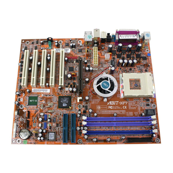
Page 32: Layout Diagram
Chapter 1 1-3. Layout Diagram BG7E... -
Page 33: Chapter 2. Hardware Setup
Hardware Setup Chapter 2. Hardware Setup ® It is required to adopt an ATX12V power supply to meet the power requirement of Pentium This motherboard provides all standard equipment for classic personal computers with great flexibility for meeting future upgrade demands. This chapter will introduce step-by-step all of the standard equipment and will also present, as completely as possible, future upgrade capabilities. -
Page 34: Nstall Entium 4 Cpu And Heatsink Supporting -Base
ATTENTION: Do not forget to set the correct bus frequency and multiple for your processor. Figure 2-3. Installing P4 Socket 478 CPU and its heatsink into supporting base. BG7E... -
Page 35: Install System Memory
Hardware Setup 2-3. Install System Memory This motherboard provides three 184-pin DDR DIMM sites for memory expansion available from minimum memory size of 64MB to maximum memory size of 2GB DDR SDRAM (DIMM2 & DIMM3 are sharing). Table 2-1. Valid Memory Configurations Bank Memory Module Total Memory... -
Page 36: Connectors, Headers And Switches
ATX12V: ATX Power Input Connectors The Pentium 4 requires a power supplier different from the regular one. It’s a newly designed ATX12V power with 300W, 20A +5VDC capacity at least for heavily loaded system, and 720mA +5VSB at least for supporting Wake-On-LAN feature. BG7E... - Page 37 Hardware Setup (2). FAN Connectors: FAN1: CPU Fan FAN2: Power Fan FAN3: Chassis Fan (3). CCMOS1: CMOS Memory Clearing Header This header uses a jumper to clear the CMOS memory. Short pin 2 and pin 3 only when you want to clear the CMOS memory.
- Page 38 Pin Assignment Pin Assignment Data0 - Data1 - Data0 + Data1 + Ground Ground FPIO1/FPIO2 Header (5). FPIO3: Infrared Device Header This header connects to an optional IR device attached to chassis. This motherboard supports standard IR transfer rates. BG7E...
- Page 39 Hardware Setup (6). FPIO4 Headers This header is used for connecting switches and LED indicators on the chassis front panel. Watch the power LED pin position and orientation. The mark “+” align to the pin in the figure below stands for positive polarity for the LED connection. Please pay attention to connect these headers. A wrong orientation will only cause the LED not lighting, but a wrong connection of the switches could cause system malfunction.
- Page 40 5-6, and pin 9-10 (default setting). Pin Assignment Pin Assignment Audio Mic. Ground Audio Mic. Bias Speaker Out Right Channel Speaker Out Right Channel Return Speaker Out Left Channel Speaker Out Left Channel Return Ground S/PDIF In S/PDIF Out BG7E...
- Page 41 Hardware Setup (8). SMB1: System Management Bus Headers This header is reserved for system management bus (SM bus). The SM bus is a specific implementation of an I C bus. I C is a multi-master bus, which means that multiple chips can be connected to the same bus and each one can act as a master by initiating a data transfer.
- Page 42 These connectors connect to the audio output of internal CD-ROM drive or add-on card. (11). AGP1: Accelerated Graphics Port Slot This slot supports an optional AGP graphics card up to AGP 4X mode. Please refer to our Web site for more information on graphics cards. BG7E...
- Page 43 Hardware Setup 2-11 (12). FDC1 Connector There are 34 wires and two connectors on each floppy cable providing two floppy disk drives connection. Connect the single end at the longer length of ribbon cable to this FDC1, and the two connectors on the other end to the floppy disk drives.
- Page 44 This motherboard carries an RTL8100B 10/100Mb Fast Ethernet controller. You can connect your system to Local Area Network through this LAN connector. • USB Port Connectors This motherboard provides two on-board USB2.0 ports to attach USB devices such as scanner, digital speakers, monitor, mouse, keyboard, hub, digital camera, joystick etc. BG7E...
-
Page 45: Chapter 3. Bios Setup
BIOS Setup Chapter 3. BIOS Setup The BIOS is a program located on a Flash Memory chip on the motherboard. This program will not be lost when you turn the computer off. This program is also referred to as the boot program. It is the only channel the hardware circuit has to communicate with the operating system. - Page 46 Since you may have to change the CMOS battery when it is out of power, and if doing so you will lose all CMOS data, we recommend that you write down all the parameters of your hardware, or to put a label with these parameters on your hard disk. BG7E...
-
Page 47: Cpu Setup [Softmenu Iii]
BIOS Setup ™ 3-1. CPU Setup [SoftMenu III] ™ The CPU can be setup through a programmable switch (CPU SoftMenu III) that replaces the traditional manual hardware configuration. This feature allows the user to more easily complete the installation procedures. You can install the CPU without configuring any jumpers or switches. The CPU must be setup according to its specifications. - Page 48 CPU and then set up the CPU parameters ™ through SoftMenu III. However, if the new CPU is slower than the old one (and is the same brand and type), we offer you two methods to successfully complete the CPU change operation. BG7E...
- Page 49 BIOS Setup Method 1: Setup up the CPU for the lowest speed for its brand. Turn the power supply off and change the ™ CPU. Then turn the system on again, and set up the CPU parameters through SoftMenu III. Method 2: Since you have to open the computer case when you change the CPU, it would be a good idea to use the CMOS clearing jumper to erase the parameters of the original CPU and to enter BIOS Setup to set up CPU parameters again.
-
Page 50: Standard Cmos Features Setup Menu
IDE HDD Auto-Detection: Press the <Enter> key for the BIOS to auto detect all detailed parameters of the hard disk drives (HDD). If auto detection is successful, the correct values will be shown in the remaining items of this menu. BG7E... - Page 51 BIOS Setup NOTE: A new IDE HDD must be first formatted, otherwise it can not read/write. The basic step in using a HDD is to make a HDD low-level format, then run FDISK, and then FORMAT the drive. Most current HDDs have already been subjected to low-level format at the factory, so you can probably skip this operation.
- Page 52 All, But Disk/Key. You can see your system memory list in the lower left box, it shows the Base Memory, Extended Memory and total Memory size configurations in your system. It is detected by the system during boot-up procedure. BG7E...
-
Page 53: Advanced Bios Features Setup Menu
BIOS Setup 3-3. Advanced BIOS Features Setup Menu With each item, you can press <Enter> at any time to display all the options for that item. ATTENTION: Advanced BIOS Features Setup Menu has already been set for maximum operation. If you do not really understand each of the options in this menu, we recommend you use the default values. - Page 54 CMOS before you can start up the system. But by doing this, you will have to reset all previously set options. APIC Mode: Two options are available: Enabled or Disabled. The default setting is Enabled. BG7E...
- Page 55 BIOS Setup 3-11 MPS Version Ctrl For OS: This item specifies which version of MPS (Multi-Processor Specification) this motherboard will use. The options are 1.1 and 1.4. The default setting is 1.4. If you use an older OS for dual processor executing, please set this option to 1.1.
-
Page 56: Advanced Chipset Features Setup Menu
The options are: 1.5, 2, and 2.5. Act to Precharge Delay: The options are: 7, 6, and 5. DRAM RAS# to CAS# Delay This item controls the latency between the DRAM active command and the read/write command. The options are: 2 and 3. BG7E... - Page 57 BIOS Setup 3-13 DRAM RAS# Precharge: This item controls the idle clocks after issuing a precharge command to the DRAM. System BIOS Cacheable: You can select Enabled or Disabled. The default setting is Enabled. When you select Enabled allows caching of the system BIOS ROM at F0000h-FFFFFh, resulting in better system performance. However, if any program writes to this memory area, a system error may result.
- Page 58 3-14 Chapter 3 On-Chip Frame Buffer Size: This option selects the size of on-chip frame buffer. Enhance DRAM Performance: Choose Enabled to enhance the system performance if there is no DRAM compatible issue occurred. The default setting is Disabled. BG7E...
-
Page 59: Integrated Peripherals
BIOS Setup 3-15 3-5. Integrated Peripherals In this menu, you can change the onboard I/O device, I/O port address and other hardware settings. Figure 3-7. Integrated Peripherals Menu Screen Onboard IDE-1 Controller: The onboard IDE 1 controller can be set as Enabled or Disabled. The default setting is Enabled. The integrated peripheral controller contains an IDE interface with support for two IDE channels. - Page 60 (right) button, for the computer to power on. You also need to note the compatibility issue with your PS/2 mouse. Some PS/2 mice cannot wake up the system because of compatibility problems. Also, if the specs of your keyboard are too old, it may fail to power on. BG7E...
- Page 61 BIOS Setup 3-17 KB Power ON Password: This option allows you to set a password required in order to Power ON your computer. You will be asked to enter your password and then to confirm it. Do not forget your password. Should you forget your password, you will have to open your computer case, clear the CMOS and reset all parameters again in order to be able to utilize this function.
-
Page 62: Power Management Setup Menu
Devices that are not being used can be turned off. The operating system uses information from applications and user settings to put the system as a whole into a low-power state. BG7E... - Page 63 BIOS Setup 3-19 Table 3-1: Wake Up Device and Events The table below describes which devices or specific events can wake the computer from specific states. These device/events can wake up the computer…… ……from this state Power switch Sleeping mode or power off mode RTC alarm Sleeping mode or power off mode Sleeping mode or power off mode...
- Page 64 This feature also allows the PCI card built-in hardware function to support the wake up function without special cables connected to the motherboard. NOTE: This feature needs a specific network interface (optional). Also your ATX power supply +5V standby power must be at least 720mA compatible. BG7E...
- Page 65 BIOS Setup 3-21 WakeUp by Ring: Two options are available: Enabled and Disabled. Default setting is Disabled. If you connect an external modem to the onboard serial port, the system will be turned on when a telephone ring-up occurs. WakeUp by Alarm: Two options are available: Enabled and Disabled.
-
Page 66: Pnp/Pci Configurations
Manual to set which IRQ is assigned to PCI PnP cards. Figure 3-10 shows you the screen of IRQ resources. Each item has two options: PCI Device and Reserved. The default setting is PCI Device. BG7E... - Page 67 BIOS Setup 3-23 Figure 3-10. IRQ Resources Setup Screen Shot PCI/VGA Palette Snoop: This option allows the BIOS to preview VGA Status, and to modify the information delivered from the Feature Connector of the VGA card to the MPEG Card. This option can solve the display inversion to black after you have used the MPEG card.
- Page 68 INT A PIRQ_3 Assignment INT C INT B PIRQ_4 Assignment INT A INT D INT C PIRQ_5 Assignment INT B INT A INT D PIRQ_6 Assignment INT C INT B INT A PIRQ_7 Assignment INT D INT C INT B BG7E...
-
Page 69: Pc Health Status
BIOS Setup 3-25 3-8. PC Health Status You can set the warning temperature for your computer system, and you can check the fan speeds and power supply voltages of your computer system. The features are useful for monitoring all the important parameters within your computer system. - Page 70 NOTE: The hardware monitoring features for temperatures, fans and voltages will occupy the I/O address from 294H to 297H. If you have a network adapter, sound card or other add-on cards that might use those I/O addresses, please adjust your add-on card I/O address to avoid using these addresses. BG7E...
-
Page 71: Load Fail-Safe Defaults
BIOS Setup 3-27 3-9. Load Fail-Safe Defaults Figure 3-12. Load Fail-Safe Defaults Screen Shot When you press <Enter> on this item you get a confirmation dialog box with a message similar to: Load Fail-Safe Defaults (Y/N) ? N Pressing “Y” loads the BIOS default values for the most stable, minimal-performance system operations. 3-10. -
Page 72: Set Password
You can determine when the password is required within the BIOS Features Setup Menu and its Security option. If the Security option is set to “System”, the password will be required both at boot and at entry to Setup. If it is set to “Setup”, the prompting only occurs when trying to enter Setup. BG7E... -
Page 73: Save & Exit Setup
BIOS Setup 3-29 3-12. Save & Exit Setup Figure 3-16. Save & Exit Setup Screen Shot Pressing <Enter> on this item asks for confirmation: Save to CMOS and EXIT (Y/N)? Y Pressing “Y” stores the selections made in the menus in CMOS - a special section of memory that stays on after you turn your system off. - Page 74 3-30 3-30 Chapter 3 Chapter 3 BG7E BG7E...
- Page 75 Install Intel Chipset Driver Appendix A. Install Intel Chipset Driver NOTE: Please install this Intel Chipset Driver before installing VGA and Audio driver. The installation procedures and screen shots in this chapter are based on Windows XP operating system. Please follow the on-screen instruction for those of other operating system.
- Page 76 Appendix A Appendix A BG7E BG7E...
- Page 77 Install Intel Application Accelerator Appendix B. Install Intel Application Accelerator NOTE: Please make sure to install the “Intel Chipset Driver” first and to reboot the system before installing this “Intel Application Accelerator”. The installation procedures and screen shots in this chapter are based on Windows XP operating system.
- Page 78 Appendix B 6. Choose “Yes, I want to restart my computer now”, and click “Finish” to end the installation. BG7E...
- Page 79 Install VGA Driver Appendix C. Install VGA Driver The installation procedures and screen shots in this chapter are based on Windows XP operating system. Please follow the on-screen instruction for those of other operating system. Insert the Installation Disk into CD-ROM drive, it should execute the installation program automatically.
- Page 80 Appendix C Appendix C BG7E BG7E...
- Page 81 Install Audio Driver Appendix D. Install Audio Driver The installation procedures and screen shots in this chapter are based on Windows XP operating system. Please follow the on-screen instruction for those of other operating system. Insert the Installation Disk into CD-ROM drive, it should execute the installation program automatically.
- Page 82 6. In this Speaker Configuration tab, check the “6 channels mode for 5.1 speakers output” box to enable 6-channel audio system. Note: To keep a normal operation of 5.1 speakers output, please do not change the settings of “Line In” and “Mic In” in this menu. BG7E...
- Page 83 Install LAN Driver Appendix E. Install LAN Driver The installation procedures and screen shots in this chapter are based on Windows XP operating system. Please follow the on-screen instruction for those of other operating system. Insert the Installation Disk into CD-ROM drive, it should execute the installation program automatically.
- Page 84 Appendix E Appendix E BG7E BG7E...
- Page 85 Install USB 2.0 Driver Appendix F. Install USB 2.0 Driver The installation procedures and screen shots in this chapter are based on Windows XP operating system. Please follow the on-screen instruction for those of other operating system. Insert the Installation Disk into CD-ROM drive, it should execute the installation program automatically.
- Page 86 Appendix F Click “Finish”. BG7E...
- Page 87 BIOS Update Guide Appendix G. BIOS Update Guide The procedure illustrated here is based on the model SE6 as an example; all other models follow the same process. 1. First, find out the model name and version number of this motherboard. You can find a sticker with model name and version number on one slot or at the back of the motherboard.
- Page 88 You may make a floppy disk bootable either in Explorer or in the DOS prompt mode. After formatting and transferring the system to the floppy disk, copy two files into it. One is the BIOS flash utility “awdflash.exe” and the other is the decompressed BIOS binary file. BG7E...
- Page 89 BIOS Update Guide 6. Boot off floppy disk. Please set the first boot sequence as “floppy” in BIOS and boot off the floppy disk. User’s Manual...
- Page 90 If this “BIOS boot block” remains intact when the BIOS becomes corrupt during programming, then you can boot from a bootable floppy next time you boot your computer. This allows you to flash your BIOS again without the need for technical support from the dealer. BG7E...
- Page 91 Hardware Monitoring (The Winbond Hardware Doctor Utility) Appendix H. Hardware Monitoring (The Winbond Hardware Doctor Utility) The Winbond Hardware Doctor is a self-diagnostic system for PCs used with Winbond W83627HF chipset. It protects PC hardware by monitoring several critical items including power supply voltages, CPU &...
- Page 92 Winbond hardware doctor on-line help. It should give you enough information to answer your questions. 8. This screen appears. Hardware Doctor shows you the status of Voltage, Fan Speed, and BG7E...
- Page 93 Installation Guide for Suspend to RAM Appendix I. Installation Guide for Suspend to RAM Suspend To RAM (STR) is a cost-effective, optimal implementation of the ACPI 1.0 specification. The ACPI specification defines the S3 sleep state, in which all system context is lost except system memory. CPU, cache, and chip set context are lost in this state.
- Page 94 2. Click “Stand by”. Restart your computer to put these settings into effect. Now you will only need to press the “Power” button on the front panel of the chassis when you want to put your computer into STR sleep mode. BG7E...
- Page 95 Troubleshooting (Need Assistance?) Appendix J. Troubleshooting (Need Assistance?) Motherboard Troubleshooting: Q & A: Q: Do I need to clear the CMOS before I use a new motherboard to assemble my new computer system? A: Yes, we highly recommend that you clear the CMOS before installing a new motherboard. Please move the CMOS jumper from its default 1-2 position to 2-3 for a few seconds, and then back.
- Page 96 Sound Card Driver. Write down the Sound Card model, motherboard model, BIOS identification number on the technical support file (refer to main instructions), and describe the problem in the space provided. We will show you how to fill the “Technical Support Form”. BG7E...
- Page 97 Troubleshooting (Need Assistance?) Main instructions: To fill in this “Technical Support Form”, refer to the step-by-step instructions given below: . MODEL: Note the model number given in your user’s manual. Example: BE7/BE7-RAID. . Motherboard model number (REV): Note the motherboard model number labeled on the motherboard as “REV:*.**”.
- Page 98 4. Choose item 2 to Select Disk Drives. There are two striping arrays built automatically and you only have to enter twice. 5. Choose item 4 to Start Creation Process. 6. Press <Esc> to finish setting and leave RAID BIOS. BG7E...
- Page 99 Troubleshooting (Need Assistance?) Q: How to rebuild a mirror array when one of the drives corrupts? A: You need to delete previous array setting, duplicate the data, and then rebuild a new array setting (See Chapter 4 for detailed information). 1.
- Page 100 Appendix J Technical Support Form Company Name: Phone Number: Contact Person: Fax Number: E-mail Address: Model BIOS ID # Motherboard Model No. DRIVER REV OS/Application Hardware Name Brand Specifications IDE1 IDE2 IDE1 CD-ROM-Drive IDE2 System Memory ADD-ON CARD Problem Description: BG7E...
- Page 101 Also please make sure you have the latest drivers from your peripheral cards makers! 3. Check the ABIT Technical Terms Guide and FAQ on our Website. We are trying to expand and make the FAQs more helpful and information rich. Let us know if you have any suggestions.
- Page 102 They should have reasonable return or refund policies. How they serve you is also a good reference for your next purchase. 6. Contacting ABIT. If you feel that you need to contact ABIT directly you can send email to the ABIT technical support department. First, please contact the support team for the branch office closest to you.
- Page 103 Unit 3, 24-26 Boulton Road Stevenage, Herts SG1 4QX, UK abituksales@compuserve.com abituktech@compuserve.com Tel: 44-1438-228888 Fax: 44-1438-226333 In Germany and Benelux (Belgium, Netherlands, Luxembourg) countries: AMOR Computer B.V. (ABIT's European Office) Van Coehoornstraat 7, 5916 PH Venlo, The Netherlands sales@abit.nl technical@abit.nl Tel: 31-77-3204428 Fax: 31-77-3204420...
- Page 104 Please contact the reseller from whom you bought the product. You should be able to get RMA service there. 8. Reporting Compatibility Problems to ABIT. Because of tremendous number of email messages we receive every day, we are forced to give greater weight to certain types of messages than to others.
Need help?
Do you have a question about the BG7E and is the answer not in the manual?
Questions and answers