
Related Manuals for Fluke 1745


Summary of Contents for Fluke 1745
- Page 1 ® 1745 Power Quality Logger Users Manual PN 2560366 April 2006 Rev.1, 7/06 © 2006 Fluke Corporation, All rights reserved. All product names are trademarks of their respective companies.
- Page 2 Fluke's warranty obligation is limited, at Fluke's option, to refund of the purchase price, free of charge repair, or replacement of a defective product which is returned to a Fluke authorized service center within the warranty period.
- Page 3 à offrir une garantie plus étendue ou différente au nom de Fluke. Le support de garantie est offert uniquement si le produit a été acquis par l’intermédiaire d’un point de vente agréé par Fluke ou bien si l’acheteur a payé...
- Page 4 Vertriebsstelle erworben oder der jeweils geltende internationale Preis gezahlt wurde. Fluke behält sich das Recht vor, dem Käufer Einfuhrgebühren für Ersatzteile in Rechnung zu stellen, falls der Käufer das Produkt nicht in dem Land zur Reparatur einsendet, in dem er das Produkt ursprünglich erworben hat.
- Page 5 Fluke autorizzato. Sono esclusi i fusibili, le pile monouso e i prodotti che, a parere della Fluke, siano stati adoperati in modo improprio, alterati, trascurati, contaminati o danneggiati in seguito a incidente o condizioni anomale d’uso e maneggiamento.
- Page 6 A obrigação da Fluke no tocante a esta garantia é limitada, a critério da Fluke, à devolução da importância correspondente ao preço pago pelo produto, a consertos gratuitos, ou à...
- Page 7 Fluke. El soporte técnico en garantía está disponible sólo si el producto se compró a través de un centro de distribución autorizado por Fluke o si el compra- dor pagó el precio internacional correspondiente. Cuando un producto comprado en un país sea enviado a otro país para su reparación, Fluke se reserva el derecho de facturar al Comprador los...
- Page 8 有限担保和有限责任 Fluke 担保在正常使用和保养的情况下,其产品没有材料和工艺上的缺陷。 两年的担保期间由产品发货之日算起。部件、产品修理和服务的担保期限为 90 天。 本担保仅限于 Fluke 授权零售商的原购买人或最终用户,并且不适用 于一次性电池、电缆接头、电缆绝缘转换接头或 Fluke 认为由于误用、改装、 疏忽、污染及意外或异常操作或处理引起的任何产品损坏。Fluke 担保软件能 依照功能规格正常运行 90 天,并且软件是记录在无缺陷的媒介上。Fluke 并不 担保软件毫无错误或在运行中不会中断。 Fluke 授权的零售商应仅对最终用户就新的和未使用的产品提供本担保,但 无权代表Fluke 公司提供额外或不同的担保。 只有通过 Fluke 授权的销售店购 买的产品或者买方已经按适用的国际价格付款才能享受 Fluke 的担保支持。 在一国购买的产品需在他国修理时,Fluke 有权向买方要求负担重大修理/零 件更换费用。 Fluke 的担保为有限责任,由 Fluke 决定是否退还购买金额、免费修理或更换 在担保期间退还 Fluke 授权服务中心的故障产品。 如需要保修服务,请与您就近的 Fluke 授权服务中心联系,获得退还授权信息;...
-
Page 9: Table Of Contents
Standard Equipment and Optional Accessories ........ 6 Features..................... 8 Power Network Configurations ............11 Working with Logged Data............... 11 Using the 1745 Power Quality Logger..........12 About Logging Jobs................12 Preparing the Logger for Use............13 Test Leads - Markings ..............15 Connecting Current Probes ............ - Page 10 1745 Users Manual Current Harmonics ................32 Mains Signaling................32 THD V – In Function A..............33 Calculation of THD in Measuring Function P......34 Flicker ..................35 Unbalance..................36 Frequency ..................36 Current Logging ................36 Logging Function A ..............36 Crest Factor (CF)................
- Page 11 List of Tables Table Title Page Symbols....................4 Standard Equipment ................7 Optional Accessories................7 1745 Power Quality Logger - Controls and Indicators....... 9 Test Leads - Markings................ 15 Measuring Ranges................26 Logging Parameters - Overview............43...
- Page 12 1745 Users Manual...
- Page 13 Title Page 1745 Power Quality Logger ............... 3 1745 Power Quality Logger - Front View.......... 8 Supplying Operating Power to the Logger ......... 14 Logging in a 3-Phase 4-Wire System ..........19 Logging in a 3-Phase 3-Wire (Delta) System........20 Single-Phase Logging ................
- Page 14 1745 Users Manual...
-
Page 15: Introduction
1745 Power Quality Logger Introduction The Fluke 1745 Power Quality Logger, see Figure 1, is a sophisticated, easy- to-use, electrical power-recording device for the electrician or power-quality specialist. Note This manual also refers to the 1745 Power Quality Logger simply as “the Logger”. -
Page 16: Logger Power Supply
1745 Users Manual Logger Power Supply The Logger does not include a power switch, but turns on automatically whenever its power supply leads are connected to a voltage in its allowed range. You can plug the Logger’s power supply leads into a standard wall... - Page 17 Power (kW, kVA, kVAR, Power PF, Power tangent) Energy, total energy Flicker (Pst, Plt) Voltage THD Current THD Current CF Voltage harmonics to the 50 (not in P function) Voltage interharmonics (not in P function) Mains signalling voltage Unbalance Frequency egc001.eps Figure 1. 1745 Power Quality Logger...
-
Page 18: Symbols
Canadian Standards Association is the certified body used for testing compliance to safety standards. Do not dispose of this product as unsorted municipal waste. Contact Fluke or a qualified recycler for disposal. Conforms to relevant Australian Standards. Safety Instructions Please read this section carefully. It will make you familiar with the most important safety instructions for using the Logger. - Page 19 Power Quality Logger Safety Instructions W X Warnings To avoid electrical shock, do not connect any part of the Logger to systems that have higher voltages to ground (earth) than are marked on the Logger. Areas between the power company meter and the source of the distribution system are characterized as CAT IV areas.
-
Page 20: Qualified Personnel
Trained or instructed in safety engineering standards for maintaining and using appropriate safety equipment. Trained in first aid. Standard Equipment and Optional Accessories Table 2 lists the standard equipment for the 1745 Power Quality Logger and Table 3 lists optional accessories. -
Page 21: Standard Equipment
Power Quality Logger Safety Instructions Table 2. Standard Equipment Equipment Model/Part Number Power Quality Logger 1745 International IEC Power Plug Adapter Set 2441372 RS232 Cable, Red, Null-Modem 2540511 Shielded 4-Phase Flexi Set (15 A/150 A/1500 A/3000 A) FS17XX Dolphin Clip, Black (4x) -
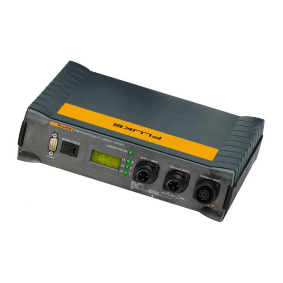
Page 22: Features
1745 Users Manual Features This section introduces the Logger’s controls, indicators and other features. Refer to Figure 2 and Table 4. egc002.eps Figure 2. 1745 Power Quality Logger - Front View... -
Page 23: Power Quality Logger - Controls And Indicators
Power Quality Logger Safety Instructions Table 4. 1745 Power Quality Logger - Controls and Indicators Item Name Description Connector for This is where the power cord attaches to the Logger power Logger. The power cord connects in parallel supply. to any two test leads as long as the voltage is below 660 V absolute maximum. - Page 24 1745 Users Manual Table 4. 1745 Power Quality Logger - Controls and Indicators (cont) Item Name Description Connector for Flexi Flexi sets or current clamps are detected Set or current automatically at power-up. If you change the clamps current probe type, be sure to remove and restore power so the Logger will detect the new current probe.
-
Page 25: Power Network Configurations
Power Quality Logger Safety Instructions Power Network Configurations You can set up the Logger to work with several power network configurations (listed below). You make these settings using PQ Log software while connected to the Logger using the interface cable. See the PQ Log Users Manual for details. -
Page 26: Using The 1745 Power Quality Logger
Users Manual Using the 1745 Power Quality Logger This section explains how to operate the 1745 Power Quality Logger. You should also refer to the PQ Log Users Manual to become familiar with the software you use to prepare the Logger for use and download logged data. -
Page 27: Preparing The Logger For Use
Power Quality Logger Using the 1745 Power Quality Logger Preparing the Logger for Use Prepare the 1745 Logger for use with PQ Log software as follows (see Figure 3): 1. Connect the Logger to line power. Use the power supply cables to connect to an outlet, or to the test leads phase and neutral for Wye configurations, or any two-phase leads for delta. - Page 28 1745 Users Manual Power in Parallel Power from Wall Outlet with Test Leads Power Supply Leads Power Supply Leads Voltage Test Leads Voltage Test Leads Max 660 V egc031.eps Figure 3. Supplying Operating Power to the Logger...
-
Page 29: Test Leads - Markings
Logging with Voltage Converters The 1745 Logger includes an adjustable convertor ratio that enables it to be used with voltage convertors (potential transformers, or PTs). Note When logging with voltage convertors, make sure the power supply cables are not connected in parallel to the voltage test leads, or the Logger’s power consumption can reduce accuracy. -
Page 30: Connecting The Logger
1745 Users Manual Connecting the Logger W X Warnings To avoid electrical shock, do not connect any part of the Logger to systems that have higher voltages to ground (earth) than are marked on the Logger. Areas between the power company meter and the source of the distribution system are characterized as CAT IV areas. - Page 31 WCaution To avoid damage, use the 1745 Power Quality Logger only with the following nominal voltages: Single/3-phase 4-wire (Wye) systems (P-N): 69 V to 480 V 3-phase-3-wire (Delta) systems (P-P): 120 V to 830 V WX Warning To avoid electrical shock, or damaging the Logger’s...
- Page 32 Connect the Logger as follows. Note - (delta) or - (wye) measurements. The 1745 Logger is prepared for logging in Delta, Delta 2 Element, Wye (Star), single and split phase. Please note the different types of connection and configuration in the PQ Log software.
-
Page 33: Connections In 3-Phase 4-Wire (Wye) Systems
Power Quality Logger Using the 1745 Power Quality Logger Connections in 3-Phase 4-Wire (Wye) Systems Figure 4 shows the connections for logging 3-phase 4-wire (Wye) systems: Power Supply egc003.eps Figure 4. Logging in a 3-Phase 4-Wire (Wye) System... -
Page 34: Connections In 3-Phase 3-Wire (Delta) Systems
1745 Users Manual Connections in 3-Phase 3-Wire (Delta) Systems Figure 5 shows the connections for logging 3-phase 3-wire (Delta) systems. The test lead “N” can be left open or connected to ground potential. Power Supply egc004.eps Figure 5. Logging in a 3-Phase 3-Wire (Delta) System... -
Page 35: Connections For Single-Phase Logging
Power Quality Logger Using the 1745 Power Quality Logger Connections for Single-Phase Logging Figure 6 shows the connections for logging single-phase logging systems: Power Supply egc005.eps Figure 6. Single-Phase Logging... -
Page 36: Connections For Medium Voltage Networks
1745 Users Manual Connections for Medium Voltage Networks In a 3-phase 3-wire (Delta) system with three separate voltage converters and three current transformers, the Logger can measure phase-phase (P-P, Delta) or phase - N (P-N, Wye). See Figure 7. Power Supply egc006.eps... - Page 37 Power Quality Logger Using the 1745 Power Quality Logger Figure 9 shows the connections for two-element Delta (Aron or Blondel) metering connections. Power Supply L2, N egc009.eps Figure 8. Two-Element Delta Connections...
-
Page 38: Logging
1745 Users Manual Logging When the Logger is connected and ready, you can perform three types of logging: Switch-activated job: The status LED is blinking. Press the START/STOP button once. As soon as the job is active, the LED is on continuously. -
Page 39: Evaluating The Logged Data
5. Once the data is transferred, remove the RS232 interface cable and operating power from the Logger. 6. Evaluate the data using PQ Log. For details, refer to the PQ Log manual. Methods of Logging The following section describes methods of logging using the 1745 Logger. -
Page 40: Voltage Ranges
1745 Users Manual Voltage Ranges The software calculates the correct measuring range depending on the nominal voltage (20 % overflow with C = 1.4). Table 6 shows the measuring ranges of the Logger and Figure 9 shows the selection for input ranges during job processing. -
Page 41: Signal Sampling
Power Quality Logger Using the 1745 Power Quality Logger Signal Sampling Input signals (up to three voltages and four currents) are filtered with an anti- aliasing filter and digitized with a 16-bit A/D converter. The sampling rate is 10.24 kHz. All parameters are calculated from this data. -
Page 42: Averaging Period
1745 Users Manual Averaging Period Averaging period can be set in PQ Log to the following: 1, 3, 5, 10, or 30 seconds 1, 5, 10, 15, or 60 minutes Figure 10 shows the measuring voltage variations of the Logger. -
Page 43: Min/Max Values
Power Quality Logger Using the 1745 Power Quality Logger Min/Max Values Logging detects the highest and lowest voltage RMS values and the highest current RMS value during the test interval, using a minimum resolution of 10 ms. The response time can be set in PQ Log to the following: 0.5, or 1 line power period... -
Page 44: Voltage Interruptions
1745 Users Manual Voltage Interruptions The Logger records two types of interruptions: All measured RMS values of input voltages that are < 1 % of the nominal voltage. This threshold can be adjusted in PQ Log. Interruptions > 1 half-cycle The start time and duration of each interruption are registered. -
Page 45: Voltage Dips And Swells
Power Quality Logger Using the 1745 Power Quality Logger Voltage Dips and Swells If the voltage passes the upper limit (V + 10 %) or lower limit (V - 10 %), the event is registered as a voltage swell or dip respectively (thresholds are adjustable in PQ Log). -
Page 46: Current Harmonics
1745 Users Manual Current Harmonics Current harmonics are defined as current components that have a frequency that is an integer multiple of the fundamental frequency of the line power current. Logging function A records ech individual harmonic of the phase... -
Page 47: Thd V - In Function A
Power Quality Logger Using the 1745 Power Quality Logger THD V – In Function A ∑ Function A: RMS value of harmonic frequency #n. RMS value of the fundamental frequency. THDV: total contents of harmonics of the line power voltage as a percentage of the fundamental. -
Page 48: Calculation Of Thd In Measuring Function P
1745 Users Manual Calculation of THD in Measuring Function P THD – Measuring Function P Function P does not measure harmonic values. THDV Voltages: RMS value of the total signal RMS: : RMS value of the fundamental THDI Currents: RMS value of the total signal... -
Page 49: Flicker
Power Quality Logger Using the 1745 Power Quality Logger Flicker Flicker is the visual impression of unsteadiness in a light source whose luminance or spectral distribution changes over time. Flicker, see Figure 14, is logged in accordance with the IEC 61000-4-15 standard. The short-term (st) -
Page 50: Unbalance
1745 Users Manual Unbalance The ratio of negative-to-positive-sequence harmonics is calculated with the angles and magnitudes of the phase voltages taken into account. These values are averaged over the interval length defined in PQ Log. Frequency The line power frequency is measured and averaged over 10 seconds and the resulting values are divided into 42 classes for establishing statistics. -
Page 51: Power
Power Quality Logger Using the 1745 Power Quality Logger Power The power values (L1 or A, L2 or B, L3 or C and N) are averaged over the interval length, and the maximum value of each is recorded. The response time can be set to 1 second or 1 minute, and is independent of the response time for voltage and current. -
Page 52: Measurement Theory
1745 Users Manual Measurement Theory The following are the equations used by the Logger and PQ Log to produce the results you see in PQ Log. Measurement Function A logs current and voltage harmonics, while Measurement Function P does not: ∑... - Page 53 Power Quality Logger Measurement Theory ∑ Active power of logging interval per phase to 200 ms value bas j M: Number of 200 ms intervals per logging intervals ∑ Total active power on all total three phases : Active power of the phase k: Phase (k = 1, 2, 3) ∑...
- Page 54 1745 Users Manual ∑ Total apparent power on total three phases k: Phase (k = 1, 2, 3) Distortion power. Basic value on 200 ms per phase ∑ Distortion power per interval per phase : 200 ms value bas j M: Number of 200 ms intervals per logging interval ∑...
- Page 55 Power Quality Logger Measurement Theory ∑ Active power of the fundamental per phase per interval ∑ Total active power of the total fundamental for three phases Apparent power of the fundamental per phase. Basic value for 200 ms. ∑ Apparent power of the fundamental per phase per interval total...
-
Page 56: Maintenance
If the Logger gets dirty, wipe it off carefully with a damp cloth without cleaning agents. Lithium Battery The 1745 Logger contains a vanadium pentoxide lithium rechargeable battery and a sealed gel-type, lead-acid battery. These batteries are automatically recharged during normal operation. Neither one is user-servicable. -
Page 57: Technical Specifications
Power Quality Logger Technical Specifications Technical Specifications Logging Parameters – Overview Table 7 shows an overview of the logging parameters. Table 7. Logging Parameters - Overview Measuring Function Voltage: mean, min, max values Current: Mean, max-values Neutral current N Voltage events Power: P, |P|, S, D, PF, tangent Power total P, |P|, S, D, PF,... -
Page 58: Maximum Number Of Intervals For Logging Funtion P
Quality system Developed, designed, and manufactured according to DIN ISO 9001. Recalibration interval Fluke recommends a recalibration interval of no more than two years, depending on use. Reference conditions 23 C ±2 K, 230 V ±10 % 50 Hz ± 0.1 Hz / 60 Hz ± 0.1 Hz... -
Page 59: Environmental Specifications
Power Quality Logger Technical Specifications Environmental Specifications Working temperature -10°C to +55°C range Operating temperature 0°C to +35°C range Storage temperature range -20°C to +60°C Reference temperature 23°C ± 2 K range Relative humidity 10 to 90 %, no condensation Housing Robust, compact housing of CYCOLOY Protection... -
Page 60: Measurement
1745 Users Manual Memory model Linear or circular, user-selectable Interface RS-232, 9600 to 115.000 Baud, automatic selection, 3-wire communication. Dimensions 170 mm x 125 mm x 55 mm Weight Approx. 0.9 kg Measurement A/D converter 16 bit Sampling frequency 10.24 kHz Anti-aliasing filter FIR-Filter, fC = 4.9 kHz... -
Page 61: Current Input With Flexi Set
Power Quality Logger Technical Specifications Current Input with Flexi Set Input ranges I L1 or A, L2 15, 150, 1500, or 3000 A AC or B, L3 or C, N: Measuring range 0.75 A to 3000 A AC Intrinsic uncertainty <... -
Page 62: General Specifications
1745 Users Manual General Specifications RMS Logging Slow Voltage Variations Logging values: Mean value RMS values averaged over interval length Min, Max values Averaging with selectable averaging time from half-cycle to 5 s Max value Max. 10 ms RMS value per interval Min value: Min. -
Page 63: Power P, S, |P
Power Quality Logger Technical Specifications Power P, S, |P| Active power P As per EN 61036, class 2 Distorting power D As per EN 61268, class 2 (A-version only) Max value Highest value per interval Min value Smallest value per interval Phase uncertainty <... -
Page 64: Logging Function Parameters
1745 Users Manual Logging Function Parameters Logging Values Voltage L1 or A, L2 or B, L3 or C: phase-phase or phase-neutral: Voltage (mean, max, min values) Voltage harmonics 1 to 50 order (Logging Function A only) THDV (harmonic contents of voltage) Interharmonics 5 to 2500 Hz (in steps of 0.5 Hz) (Logging Function A... -
Page 65: Applications
Power Quality Logger Technical Specifications Applications Power quality: Voltage quality analysis according to EN 50160 over a 1-week period (time-activated job) Examination of measurement quantities per standards Disturbance analysis: Long-term analysis of line power voltage Examination of voltage dips, swells, and harmonic problems (Logging Function A only) Flicker measurement Examination of ripple control signals (level) (Logging Function A... -
Page 66: Pq Log Pc Application Software
1745 Users Manual PQ Log PC Application Software PQ Log for PCs is the application for use with the 1745 Power Quality Logger. The data are also available in ASCII format. Programs available for setting up the Logger: Averaging period length... -
Page 67: Live Reading (Online Test)
Power Quality Logger PQ Log PC Application Software Live Reading (Online Test) Figure 15 shows a typical display of online test: egb024.bmp Figure 15. Live Reading (Online Test) -
Page 68: Ascii Export
1745 Users Manual ASCII Export Figure 16 shows a typical display of ASCII export. egb025.bmp Figure 16. ASCII Export For special cases, additional evaluations are available: Graphic representation of measured data Timeplot diagrams Application oriented analysis Logging value list Table of events (UNIPEDE DISDIP) -
Page 69: Timeplot Diagram
Power Quality Logger PQ Log PC Application Software Timeplot Diagram Figure 17 shows a typical display of Timeplot diagram: egb026.bmp Figure 17. Timeplot Diagram... -
Page 70: Unipede Disdip Table
1745 Users Manual UNIPEDE DISDIP Table Figure 18 shows a typical display of UNIPEDE DISDIP table: egb027.bmp Figure 18. UNIPEDE DISDIP Table Cumulative Frequency – Harmonics Figure 19 shows a typical display of cumulative frequencies for current and voltage harmonics: egb028.bmp... -
Page 71: Index
Index Logging input for voltages, 10 —A— Logging segments, 12 Anti aliasing filter, 27 —M— Apparent Power, 37 Maximum nominal voltages, 6, 17 —C— Methods of Logging, 25 Completing the Logging, 24 —N— Connecting the clip on probes, 15 Connection modes, 26 Nominal Voltage, 26 Connections for Medium Voltage —P—... - Page 72 1745 Users Manual...
Need help?
Do you have a question about the 1745 and is the answer not in the manual?
Questions and answers