Table of Contents
Advertisement
Owner's Manual & Safety Instructions
Save This Manual
inspection, maintenance and cleaning procedures. Write the product's serial number in the back of the manual
near the assembly diagram (or month and year of purchase if product has no number). Keep this manual and
the receipt in a safe and dry place for future reference.
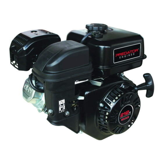
Horizontal Engines
Using an engine indoors
CAN KILL YOU IN MINUTES.
Engine exhaust contains carbon monoxide.
This is a poison you cannot see or smell.
NEVER use inside
a home or garage,
EVEN IF doors and
windows are open.
Visit our website at: http://www.harborfreight.com
Email our technical support at: predator@harborfreight.com
Manual Revised 11k
When unpacking, make sure that the product is intact
and undamaged. If any parts are missing or broken,
please call 1-800-520-0882 as soon as possible.
©
Copyright
2010 by Harbor Freight Tools
No portion of this manual or any artwork contained herein may be reproduced in
any shape or form without the express written consent of Harbor Freight Tools.
Diagrams within this manual may not be drawn proportionally. Due to continuing
improvements, actual product may differ slightly from the product described herein.
Tools required for assembly and service may not be included.
Keep this manual for the safety warnings and precautions, assembly, operating,
212, 346 and 420 cc
Only use OUTSIDE
and far away from
windows, doors,
and vents.
®
. All rights reserved.
ITEMS 68120, 68121,
Read this material before using this product.
Failure to do so can result in serious injury.
SAVE THIS MANUAL.
68136, 68306
Advertisement
Table of Contents

Related Manuals for Predator Engines PREDATOR 212


Summary of Contents for Predator Engines PREDATOR 212
- Page 1 No portion of this manual or any artwork contained herein may be reproduced in Failure to do so can result in serious injury. any shape or form without the express written consent of Harbor Freight Tools. Diagrams within this manual may not be drawn proportionally. Due to continuing SAVE THIS MANUAL.
-
Page 2: Table Of Contents
Table of Contents Specifications ..........2 Maintenance ..........14 Safety ............3 Troubleshooting ......... 18 Setup ............6 Warranties ..........20 Operation ............ 8 Parts Lists and Diagrams ......22 Specifications Description 68120, 68121 68136 68306 Displacement 212cc 346cc 420cc Engine Type Horizontal Single Cylinder 4 stroke OHV Cooling System... -
Page 3: Safety
WARNING SYMBOLS AND DEFINITIONS This is the safety alert symbol. It is used to alert you to potential personal injury hazards. Obey all safety messages that follow this symbol to avoid possible injury or death. Indicates a hazardous situation which, if not avoided, will result in death or serious injury. -
Page 4: Operating Precautions
Caution is necessary when near the engine’s magneto or recoil starter. 14. Use only accessories that are recommended by Harbor Freight Tools for your model. Accessories that may be suitable for one piece of equipment may become hazardous Only use OUTSIDE and far away from windows, when used on another piece of equipment. - Page 5 5. Maintain labels and nameplates on the equipment. These carry important information. If unreadable or missing, contact 68121 Max Fuel Harbor Freight Tools for a replacement. DO NOT OVERFILL! 6. Have the equipment serviced by a qualified repair person using only identical replacement parts.
-
Page 6: Setup
Set Up Read the ENTIRE IMPORTANT SAFETY INFORMATION section at the beginning of this manual including all text under subheadings therein before set up or use of this product. Model 68120: The emission control system for this engine is warranted for standards set by the U.S. Environmental Protection Agency. -
Page 7: Engine Controls
Engine Controls Fuel Cap Air Filter Engine Switch (Electric Start Models) Starter Handle Muffler Oil Drain Plug Throttle Dipstick Choke Starter Fuel Valve (Electric Start Models) Serial Number Location (Write on front cover of manual.) Engine Switch (Manual Start Models) Horizontal Engines For technical questions, please call 1-800-520-0882. -
Page 8: Operation
Operation Read the ENTIRE IMPORTANT SAFETY INFORMATION section at the beginning of this manual including all text under subheadings therein before set up or use of this product. Pre-Start Checks Inspect engine and equipment looking for damaged, loose, and missing parts before set up and starting. -
Page 9: Starting The Engine
Checking and Filling Fuel Note: Do not use gasoline containing more than WARNING! TO PREVENT SERIOUS 10% ethanol (E10). Do not use E85 ethanol. INJURY FROM FIRE: Fill the fuel tank in a well-ventilated area Note: Do not use gasoline that has been stored in a away from ignition sources. -
Page 10: Manual Start
Manual Start 1. To start a cold engine, move the Choke to the CHOKE position. To restart a warm engine, leave the Choke in the RUN position. CHOKE 2. Open the Fuel Valve. 3. Slide the Throttle or Speed Control Lever to 1/3 away from the SLOW position (the “turtle”). -
Page 11: Stopping The Engine
6. Allow the Engine to run for several seconds. Then, if the Choke lever is in the CHOKE position, move the Choke Lever very slowly to its RUN position. Note: Moving the Choke Lever too fast could stall the engine. CHOKE IMPORTANT: Allow the engine to run at no load for five minutes with no load after each start-up so that the engine can stabilize. - Page 12 Electric Start (if equipped) 1. To start a cold engine, move the Choke to the CHOKE position. To restart a warm engine, leave the Choke in the RUN position. CHOKE 2. Open the Fuel Valve. 3. Slide the Throttle or Speed Control Lever to 1/3 away from the SLOW position (the “turtle”).
- Page 13 5. Allow the Engine to run for several seconds. Then, if the Choke lever is in the CHOKE position, move the Choke Lever very slowly to its RUN position. Note: Moving the Choke Lever too fast could stall the engine. CHOKE IMPORTANT: Allow the engine to run at no load for five minutes with no load after each start-up so that the engine can stabilize.
-
Page 14: Maintenance
Maintenance WARNING TO PREVENT SERIOUS INJURY FROM ACCIDENTAL STARTING: Turn the Power Switch of the equipment to its “OFF” position, wait for the engine to cool, and disconnect the spark plug cap before performing any inspection, maintenance, or cleaning procedures. TO PREVENT SERIOUS INJURY FROM EQUIPMENT FAILURE: Do not use damaged equipment. -
Page 15: Checking And Filling Fuel
Checking and Filling Fuel Engine Oil Change WARNING! TO PREVENT SERIOUS CAUTION! Oil is very hot during operation and can INJURY FROM FIRE: cause burns. Wait for engine to cool before changing oil. Fill the fuel tank in a well-ventilated area 1. - Page 16 Air Filter Element Maintenance Spark Plug Maintenance 1. Remove the air filter cover and the air filter elements and check for dirt. Spark Clean or replace as described below. Plug 2. Cleaning: • For “paper” filter elements: To prevent injury from dust and debris, wear ANSI-approved safety goggles, NIOSH-approved dust mask/respirator, and heavy-duty work gloves.
- Page 17 Storage When the equipment is to remain idle for longer than d. Open the fuel valve. After all fuel has 20 days, prepare the engine for storage as follows: drained, reinstall the drain bolt and sediment cup (if equipped). Tighten securely. 1.
-
Page 18: Troubleshooting
Troubleshooting Problem Possible Causes Probable Solutions Engine will not start FUEL RELATED: FUEL RELATED: 1. No fuel in tank or fuel valve closed. 1. Fill fuel tank and open fuel valve. 2. Choke not in CHOKE position, cold engine. 2. Move Choke to CHOKE position. 3. -
Page 19: Probable Solutions
Problem Possible Causes Probable Solutions Engine misfires 1. Spark plug cap loose. 1. Check wire connections. 2. Incorrect spark plug gap or 2. Re-gap or replace spark plug. damaged spark plug. 3. Defective spark plug cap. 3. Replace spark plug cap. 4. -
Page 20: Warranties
Limited 90 Day Warranty Harbor Freight Tools Co. makes every effort to assure that its products meet high quality and durability standards, and warrants to the original purchaser that this product is free from defects in materials and workmanship for the period of 90 days from the date of purchase. - Page 21 If you have any questions regarding your warranty rights and to the effect of “repair or replace as necessary” are warranted for responsibilities, you should contact the Harbor Freight Tools Customer the warranty period. Any warranted part which is scheduled for Service Department at 1-800-520-0882.
-
Page 22: Parts Lists And Diagrams
Parts Lists and Diagrams 68120 212cc Parts List Part Description Qty. Part Description Qty. Gasket, Cylinder Head Rocker, Valve Cover Asm., Cylinder Head Nut_ Valve Adjusting Gasket, Cylinder Head Cover Nut, Valve Lock Tube, Breather Spring, Valve Bolt Starter Asm., Recoil Stud Bolt Stud... -
Page 23: Assembly Diagram
68120 212cc Assembly Diagram Horizontal Engines For technical questions, please call 1-800-520-0882. Page 23... - Page 24 68121 212cc Parts List Part Description Qty. Part Description Qty. Gasket, Cylinder Head Starter Asm., Recoil Cover Asm., Cylinder Head Bolt Gasket, Cylinder Head Cover Shroud Tube, Breather Shroud, Cylinder Body Bolt Shield,Lower Stud Protector, Oil Stud Switch Asm., Stop Engine Stud Bolt Bolt...
- Page 25 68121 212cc Assembly Diagram Horizontal Engines For technical questions, please call 1-800-520-0882. Page 25...
- Page 26 68136 346cc Parts List Part Description Qty. Part Description Qty. Gasket, Cylinder Head Plate Asm., Lifter Stopper Cover Asm., Cylinder Head Bolt, Valve Adjusting Gasket, Cylinder Head Cover Rocker, Valve Tube, Breather Nut, Valve Adjusting Bolt Asm., Cylinder Head Cover Nut, Valve Lock Stud Spring, Valve...
- Page 27 68136 346cc Assembly Diagram Horizontal Engines For technical questions, please call 1-800-520-0882. Page 27...
- Page 28 68306 420cc Parts List Part Description Qty. Part Description Qty. Gasket, Cylinder Head Retainer, Valve Spring Cover Asm., Cylinder Head Starter Asm., Recoil Gasket, Cylinder Head Cover Bolt Tube, Breather Shroud Bolt Asm., Cylinder Head Cover Shroud, Cylinder Body Stud Bolt Stud Bolt...
- Page 29 68306 420cc Assembly Diagram REV 11k Horizontal Engines For technical questions, please call 1-800-520-0882. Page 29...
- Page 30 Mounting Hole Diagrams Note: Not to scale. ITEM 68120 / 68121 212cc 6.38 in. / 162mm 2.6 in. / 66mm ITEM 68136 346cc and ITEM 68306 420cc 7.72 in. / 196mm 4.13 in. / 105mm Page 30 For technical questions, please call 1-800-520-0882. Horizontal Engines...
- Page 31 Power Take-Off Diagrams Note: Not to scale. ITEM 68120 / 68121 212cc 2.43 in. / 61.7mm 5/16-24UNF 1.79 in. / 45.5mm 0.67 in. / 17mm 0.1875 in. / 4.78mm Ø0.75 in. / 19.05mm Ø3.625 in. / 92mm 4x5/16-24UNF ITEM 68136 346cc and ITEM 68306 420cc Ø3.625 in.
- Page 32 3491 Mission Oaks Blvd. • PO Box 6009 • Camarillo, CA 93011 • (800) 520-0882 www.harborfreight.com...