Table of Contents
Advertisement
Advertisement
Table of Contents

Subscribe to Our Youtube Channel
Related Manuals for Predator Engines 420cc


Summary of Contents for Predator Engines 420cc
-
Page 2: Table Of Contents
Troubleshooting ......... 18 Setup ............6 Warranties ..........23 Operation ............ 9 Parts List and Diagram ......20 Specifications Displacement 420cc Horizontal Single Cylinder 4 stroke OHV Engine Type EPA phase III compliant Cooling System Forced air cooled Type 87+ octane unleaded gasoline... -
Page 3: Safety
WARNING SYMBOLS AND DEFINITIONS This is the safety alert symbol. It is used to alert you to potential personal injury hazards. Obey all safety messages that follow this symbol to avoid possible injury or death. Indicates a hazardous situation which, if not avoided, will result in death or serious injury. -
Page 4: Operating Precautions
Caution is necessary when near the engine’s magneto or recoil starter. 14. Use only accessories that are recommended by Harbor Freight Tools for your model. Accessories that may be suitable for one piece of equipment may become hazardous Only use OUTSIDE and far away from windows, when used on another piece of equipment. - Page 5 These carry important information. 4. Refuel in a well-ventilated area only. If unreadable or missing, contact Harbor Freight Tools for a replacement. 5. Wipe up any spilled fuel and allow excess to evaporate before starting engine. To prevent FIRE, do not start the engine while the smell of fuel hangs in the air.
-
Page 6: Setup
Set Up Read the ENTIRE IMpORTANT SAFETY INFORMATION section at the beginning of this manual including all text under subheadings therein before set up or use of this product. At high altitudes, the engine’s carburetor, governor (if so equipped), and any other parts that control the fuel-air ratio will need to be adjusted by a TO pREVENT SERIOUS INJURY: Operate only with proper spark arrestor installed. -
Page 7: Engine Controls
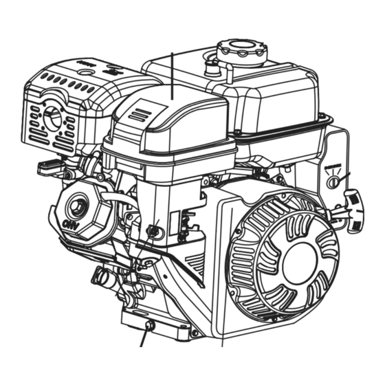
Engine Controls Fuel Cap Air Filter Engine Switch Starter Handle Muffler Oil Drain plug Throttle Dipstick Choke Starter Fuel Valve Serial Number Location (Write on front cover of manual.) ITEM 69736 For technical questions, please call 1-800-520-0882. Page 7... - Page 8 High Altitude Operation Above 3000 feet WARNING! TO pREVENT SERIOUS INJURY FROM FIRE: Follow instructions in a well-ventilated area away from ignition sources. If the engine is hot from use, shut the engine off and wait for it to cool before proceeding. Do not smoke. NOTICE Warranty void if necessary adjustments are not made for high altitude use.
-
Page 9: Operation
Operation Read the ENTIRE IMpORTANT SAFETY INFORMATION section at the beginning of this manual including all text under subheadings therein before set up or use of this product. pre-Start Checks Inspect engine and equipment looking for damaged, loose, and missing parts before set up and starting. If any problems are found, do not use equipment until fixed properly. -
Page 10: Manual Start
Manual Start 1. To start a cold engine, move the Choke to the CHOKE position. To restart a warm engine, leave the Choke in the RUN position. CHOKE 2. Open the Fuel Valve. 3. Slide the Throttle or Speed Control Lever to 1/3 away from the SLOW position (the “turtle”). -
Page 11: Stopping The Engine
6. Allow the Engine to run for several seconds. Then, if the Choke lever is in the CHOKE position, move the Choke Lever very slowly to its RUN position. Note: Moving the Choke Lever too fast could stall the engine. CHOKE IMpORTANT: Allow the engine to run at no load for five minutes with no load after each start-up so that the engine can stabilize. - Page 12 Electric Start (if equipped) 1. To start a cold engine, move the Choke to the CHOKE position. To restart a warm engine, leave the Choke in the RUN position. CHOKE 2. Open the Fuel Valve. 3. Slide the Throttle or Speed Control Lever to 1/3 away from the SLOW position (the “turtle”).
- Page 13 5. Allow the Engine to run for several seconds. Then, if the Choke lever is in the CHOKE position, move the Choke Lever very slowly to its RUN position. Note: Moving the Choke Lever too fast could stall the engine. CHOKE IMpORTANT: Allow the engine to run at no load for five minutes with no load after each start-up so that the engine can stabilize.
-
Page 14: Maintenance
Maintenance WARNING TO pREVENT SERIOUS INJURY FROM ACCIDENTAL STARTING: Turn the power Switch of the equipment to its “OFF” position, wait for the engine to cool, and disconnect the spark plug cap before performing any inspection, maintenance, or cleaning procedures. TO pREVENT SERIOUS INJURY FROM EQUIpMENT FAILURE: Do not use damaged equipment. -
Page 15: Checking And Filling Fuel
Checking and Filling Fuel Engine Oil Change WARNING! TO pREVENT SERIOUS CAUTION! Oil is very hot during operation and can INJURY FROM FIRE: cause burns. Wait for engine to cool before changing oil. Fill the fuel tank in a well-ventilated area 1. - Page 16 Air Filter Element Maintenance Spark plug Maintenance 1. Remove the air filter cover and the air filter elements and check for dirt. Spark Clean or replace as described below. plug 2. Cleaning: • For “paper” filter elements: To prevent injury from dust and debris, wear ANSI-approved safety goggles, NIOSH-approved dust mask/respirator, and heavy-duty work gloves.
- Page 17 Storage When the equipment is to remain idle for longer than d. Open the fuel valve. After all fuel has drained, 20 days, prepare the engine for storage as follows: reinstall the drain bolt and sediment cup (if equipped). Tighten securely. 1.
-
Page 18: Troubleshooting
Troubleshooting problem possible Causes probable Solutions Engine will not start FUEL RELATED: FUEL RELATED: 1. No fuel in tank or fuel valve closed. 1. Fill fuel tank and open fuel valve. 2. Choke not in CHOKE position, cold engine. 2. Move Choke to CHOKE position. 3. -
Page 19: Probable Solutions
problem possible Causes probable Solutions Engine misfires 1. Spark plug cap loose. 1. Check wire connections. 2. Incorrect spark plug gap or 2. Re-gap or replace spark plug. damaged spark plug. 3. Defective spark plug cap. 3. Replace spark plug cap. 4. -
Page 20: Parts List And Diagram
parts List and Diagram parts List part Description Qty. part Description Qty. Gasket, Cylinder Head Plate Subassembly, Lifter Stopper Cover Subassembly, Cylinder Head Bolt, Rocker Shaft Gasket, Cylinder Head Cover Rocker, Valve Tube, Breather Nut, Valve Adjusting Bolt, Cylinder Head Nut, Valve Lock Washer Set Spring, Valve... -
Page 21: Assembly Diagram
ITEM 69736 For technical questions, please call 1-800-520-0882. Page 21... - Page 22 Mounting Hole Diagram Note: Not to scale. 7.72 in. / 196mm 4.13 in. / 105mm power Take-Off Diagram Note: Not to scale. Ø3.625 in. / 92mm (30°) (30°) 3.48 in. / 88.5mm Ø6.5 in. / 165.1mm 0.25 in. / 6.35mm Ø1 in.
-
Page 23: Warranties
Limited 90 Day Warranty Harbor Freight Tools Co. makes every effort to assure that its products meet high quality and durability standards, and warrants to the original purchaser that this product is free from defects in materials and workmanship for the period of 90 days from the date of purchase. - Page 24 Harbor Freight Tools Emission Control Defects Service and Maintenance Warranty provisions Component parts which are not scheduled for replacement as required maintenance or are scheduled only for regular inspection Length of Coverage to the effect of “repair or replace as necessary” are warranted for HFT warrants to a first retail purchaser and each subsequent the warranty period.
Need help?
Do you have a question about the 420cc and is the answer not in the manual?
Questions and answers
show the place to put oil in engine
The oil fill location on a Predator 420cc engine is accessed by removing the dipstick. The dipstick is threaded and should be removed by turning it counterclockwise.
This answer is automatically generated