Table of Contents
Advertisement
Quick Links
Download this manual
See also:
Quick Reference Manual
Advertisement
Table of Contents

Related Manuals for Panasonic Studio System 300


Summary of Contents for Panasonic Studio System 300
- Page 1 Panasonic Solutions Company Studio System 300 Basic Installation Guide...
-
Page 2: Table Of Contents
Panasonic Solutions Company Table Of Contents DESCRIPTION Page DESCRIPTION Page Important Power OFF Block Diagram Introduction GPI Menu Base Station AG-BS300 Battery Menu HPX370 and HPX500 Camera Adaptor AG-CA300 Battery Menu HDX900 though HPX3700 Battery Mount GenLock Menu Settings ROP AG-EC4... -
Page 3: Important Power Off
Panasonic Solutions Company IMPORTANT POWER OFF Please make sure the power is turned OFF on all equipment before making any connections! -
Page 4: Introduction
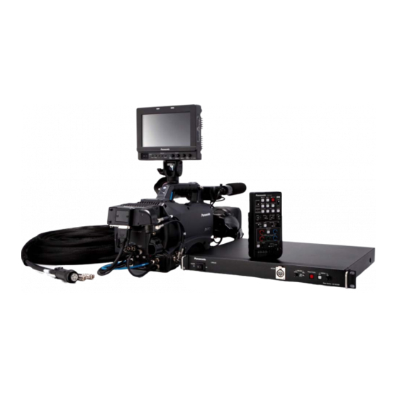
Panasonic Solutions Company Section 1 - Studio System 300 Introduction The Studio System 300 will work with the following cameras: AG-HPX300, AGHPX370, AGHPX500, AJ-HDX900, AJ-HPX2000, AJ-HPX2700, AJ-HPX3000, AJ-HPX3100 and AJ-HPX3700. Before installation of the Studio System 300, Lets review all of the components and its function. -
Page 5: Base Station Ag-Bs300
Panasonic Solutions Company Section 1 - Studio System 300 Base Station – AG-BS300 Front Back The Base Station AG-BS300 is the heart of the system. It provides the following: Power to the Camera*, Tally, Intercom, GenLock, Return Video (SDI or Video or Both) and ROP Control. -
Page 6: Camera Adaptor Ag-Ca300
Panasonic Solutions Company Section 1- Studio System 300 Camera Adaptor – AG-CA300 Right Left Back The Camera Adaptor AG-CA300 attaches to the Anton Bauer Gold Mount on the back of the Camera. It does the following: Connects to the GenLock, SDI Out, ROP, Provides Intercom, Return Video (SDI or Video or Both), GPI, Tally, Tally Out Trigger and Power. -
Page 7: Battery Mount
Panasonic Solutions Company Section 1- Studio System 300 Battery Mount Option – Anton Bauer Gold Mount If using a fiber option to run a cable length more than 100 M, power must be provided locally at the camera head. The supplied Anton Bauer Gold Battery Mount must be used. -
Page 8: Rop Ag-Ec4
Panasonic Solutions Company Section 1- Studio System 300 Remote Operation Panel (ROP) AG-EC4 Front Back The Remote Operation Panel (ROP) AG-EC4 is a simple control panel that works with all system supported cameras. This includes the following:HPX300, HPX370, HPX500, HDX900,... - Page 9 Panasonic Solutions Company Section 1- Studio System 300 Optional Remote Operation Panel AJ-RC10 Not Recommended for AG-HPX300, AG-HPX370 or AG-HPX500 The AJ-RC10 is a full featured Remote Operation Panel. It is recommended for the Cameras that offer more control options. Example: Knee and Slope Controls, Master Gama, Etc.
-
Page 10: View Finder Interface Ag-Ya500
Panasonic Solutions Company Section 1- Studio System 300 View Finder Interface Box– AG-YA500 Not Available for AG-HPX300 or AG-HPX370 The AG-YA500 VF Interface Box allows Return Video and Tally to be sent to the View Finder. This option is usually used when... - Page 11 Panasonic Solutions Company Section 2 – Cable Identification Studio 300 Cable The Studio 300 Cable connects the Camera Adaptor AG-CA300 to the Base Station AG-BS300. It is available in lengths of 25, 50 or 100 Meters. It contains a DC Power Cable and 2 Part #’s...
- Page 12 Panasonic Solutions Company Section 2 – Cable Identification Studio300 Cable To increase cable reliability, please loop the studio cable through the strain relieve and secure with the supplied cable strap as shown. Cable Strap In order to make the BNC Connection...
-
Page 13: Rop Cable 10M
Panasonic Solutions Company Section 2 – Cable Identification 10M ROP Cable The 10 Meter ROP Cable Connects the AG-EC4 (or AJ-RC10) to the Base Station AG-BS300 Remote In. It is also available in 50 Meter lengths. AG-BS300 AG-EC4... -
Page 14: Rop Cable 9
Panasonic Solutions Company Section 2 – Cable Identification 9” ROP Cable The 9” ROP Cable Connects the Camera Adaptor AG-CA300 Remote to the Camera Remote. This Cable Must Be connected for the system to work. The connection is very delicate so please handle with extreme care and make sure all power is off. -
Page 15: Genlock And Sdi
Panasonic Solutions Company Section 2 – Cable Identification GENLOCK and SDI These 2 short BNC cables connect: 1. AG-CA300 Camera Adaptor GenLock Out to the Camera GenLock In. 2. AG-CA300 SDI in to the Camera SDI Out. Note: When connecting to the HPX300, HPX370 or HPX500, these cameras will automatically GenLock when the GenLock Cable is connected. -
Page 16: Vf Gpi/Return Cable
Panasonic Solutions Company Section 2 – Cable Identification GPI/Return VF Cable From Camera Component On Board Monitor AG-CA300... -
Page 17: Lens Return Cable
Panasonic Solutions Company Section 2 – Cable Identification Optional – Lens Return Cable (Part # 300LensReturn) LENS LENS PORT The 300LensReturn Cable allows return video switching via the Lens Ret Switch or Rear Lens Controls. See the CTRL next page for connection details. - Page 18 Panasonic Solutions Company Section 2 – Cable Identification Optional – Lens Return Cable (Part # 300LensReturn) Connect a cable which is remaining to CA300 RET Remove Lens Cable CTRL terminal. Insert Lens Y Cable...
- Page 19 Panasonic Solutions Company Section 2 – Cable Identification Optional – Lens Return w/ Tally (Part # 300LensYTally) LENS The 300LensYTally is similar to the 300LensReturn cable with the following difference: It allows the Tally Out signal from the AG-CA300. LENS...
- Page 20 Panasonic Solutions Company Section 2 – Cable Identification Optional –Tally Trigger Cable (Part # 300TallyTrigger) Note: For use only with the AG-HPX300, AG-HPX370 and AJ-HPX3100. Allows Tally Lights on the Camera View Finder and Camera Body to illuminate. Also, the internal VF Tally will illuminate. Connect the 6 Pin RET CTRL on the...
- Page 21 Panasonic Solutions Company Section 2 – Cable Identification Optional – Power Tap 28” (Part # PowerTap28) This cable Provides 12 Volt DC Power for the On Board Monitor. Connect the P-Tap Plug to the P-Tap Jack on the Camera. Connect the 4 Pin XLR to the Monitor DC In.
- Page 22 Panasonic Solutions Company Section 2 – Cable Identification Optional – Multi P-Tap Adaptor (Part # PowerTap-Multi) Some Configurations require more than one P-Tap. The Multi Tap will give a total of 4 P-Tap 12 Volt DC outputs. An Example would be using the AJA Fido TR Fiber Option.
- Page 23 Panasonic Solutions Company Section 2 – Cable Identification Optional – BT-CS910G VF Cable Not for use on AG-HPX300, AG-HPX370 or AG-HPX500 The BT-CS910G Cable allows the on board monitor (BT-LH910 or BT-LH80) to use the camera VF out connector. This will provide all VF on screen status information and markings.
- Page 24 Panasonic Solutions Company Section 2 – Cable Identification Optional – AJA P-Tap Power Cable This cable Provides 12 Volt DC Power for Optional AJA Fido TR Fiber Device or for an AJA DA. Example: AG-HPX500 has only 1 SDI out. This camera will need the AJA DA to provide additional SDI outputs.
- Page 25 Panasonic Solutions Company Section 3 – System Overview...
- Page 26 Panasonic Solutions Company Section 4 – MENU SETUP On Board Monitor GPI Assignment Press Menu button on Panasonic Monitor Select GPI GPI Control = Enable GPI 1 = R-Tally GPI 2 = G-Tally GPI 3 = INPUT SEL. YP GPI 4 = INPUT SEL. SDI1 (or VF if using BT-CS910G cable)
- Page 27 Panasonic Solutions Company Section 4 – MENU SETUP Camera Battery Menu Setup AG-HPX300, AG-HPX370 and AG-HPX500 Press Menu button. Select Battery Setup. Battery Select = Type B Scroll Down to Type B and select values. Full = 13.0V ...
- Page 28 Panasonic Solutions Company Section 4 – MENU SETUP Camera Battery Menu Setup AJ-HDX900, AJ-HPX2000, AJ-HPX2700, AJ-HPX3000, AJ-HPX3100, AJ-HPX3700 Press and hold the menu button for 2 seconds to enter menu. Select Main Operation. Select Battery/P2 Card Battery Select = Type B...
- Page 29 Panasonic Solutions Company Section 5 – MENU SETUP Genlock Menu Setup AJ-HDX900, AJ-HPX2000, AJ-HPX2700, AJ-HPX3000, AJ-HPX3100, AJ-HPX3700 Press and hold the menu button for 2 seconds to enter menu. Select System Settings. Select Genlock Genlock = GL IN or EXT (depending on camera)
- Page 30 Panasonic Solutions Company Section 5 – MENU SETUP SDI Video Out Setup AJ-HDX900, AJ-HPX2000, AJ-HPX3000 AJ-HDX900 Set the Video Out Switch to HS-SDI or SD-SDI respectively. AJ-HPX2000 The switch is located under the camera side door. AJ-HDX3000 AJ-HPX2700, AJ-HDX3700 AJ-HPX2700 Set the HD-SDI A-B Switch to MEM or CAM.
- Page 31 Panasonic Solutions Company Section 5 – Intercom Connection RTS TW Intercom Connection to AG-BS300 1. Set INCOM switch on BS-300 to RTS (2 wire, AKA TW). AG-BS300 2. Turn down all volume levels before powering on. 3. Connect Pin 8 on AG-BS300 to Common (pin 1) on RTS TW.
- Page 32 Panasonic Solutions Company Section 5 – Intercom Connection Clear-Com Intercom Connection to AG-BS300 A Clear-Com IF4W-4 Interface is required to connect to the AG-BS300. AG-BS300 1. Set INCOM switch on AG-BS300 to 4W 2. Turn down all volume levels before powering on.
- Page 33 Panasonic Solutions Company Section 6 – AG-HPX500 DA Using the AG-HPX500 with an on Board Monitor The AG-HPX500 uses a Standard Definition B&W View Finder. This image will appear very soft if the on board monitor was connected to the camera VF Out. For this reason, we DO NOT recommend the BT-CS910G VF cable.
- Page 34 Panasonic Solutions Company Section 6 – AG-HPX500 DA BT-Mount PowerTap28 MultiTap SDI OUT...
- Page 35 Panasonic Solutions Company Section 7 – Fiber Options AJA FIDO TR The AJA Fido TR will allow the Studio System 300 to work with a distance of up to 6.2 miles using Low Cost Single Mode Duplex Fiber Cable with LC Termination.
- Page 36 Panasonic Solutions Company Section 7 – Fiber Options AJA FIDO TR Mounts to AG-CA-300 Bracket Not Shown Single Mode Duplex Fiber Up To 6.2 Miles 12 VDC IN VIA Gold Mount (adaptor not shown) 12VDC Cable To Camera D-Tap AC Adaptor...
- Page 37 Panasonic Solutions Company Section 8 – Trouble Shooting Common Issues Remote Control (ROP) Problem: No ROP Control and ROP shows Initializing (RC10) or dashes (EC4)? Solutions: A: Confirm that the 9” ROP is attached from the AG-CA300 remote connector to the other end to...
-
Page 38: Gpi Menu
Panasonic Solutions Company Section 8 – Trouble Shooting Common Issues Base Station lights Flash and nothing works. Problem: The Base Station light is flashing and nothing works? Solutions: A: Check that all connections are correct and no cables are swapped. -
Page 39: Tally Trigger Cable
Panasonic Solutions Company Section 9 – Accessory List PART NUMBER DESCRIPTION Page Studio Cable 300/100 100M Studio Cable Studio Cable 300/50 50M Studio Cable Studio Cable 300/25 25M Studio Cable 300LensReturn Lens Return Control Cable 300LensYTally Lens Return Control Cable w/ Tally Out option... - Page 40 Panasonic Solutions Company Section 10 – Reference Studio System Power Connectors...
- Page 41 Panasonic Solutions Company Section 10 – Reference Studio System Power Cable...
- Page 42 Panasonic Solutions Company Section 10 – Reference 300LensReturn Cable...
- Page 43 Panasonic Solutions Company Section 10 – Reference 300LensYTally Cable...
- Page 44 Panasonic Solutions Company Section 10 – Reference 300TallyTrigger Cable...
-
Page 45: Av-Hs400A Tally Connection
Panasonic Solutions Company Section 10 – Reference AV-HS400A Tally Connection... -
Page 46: Av-Hs450 Tally Connection
Panasonic Solutions Company Section 10 – Reference AV-HS450 Tally Connection... - Page 47 Panasonic Solutions Company Section 10 – Reference Prompter...
-
Page 48: Vf Cable
Panasonic Solutions Company Section 10 – Reference Common Replacement Parts Panasonic Parts Center 800-334-4881 VF Cable 10M Remote Cable 9” Remote Cable # VEE1G49 # K1EY10YY0001 # VEE1G47 2 short BNC Cables for AG-CA300 To Camera SDI and GenLock Cable Strap... - Page 49 Panasonic Solutions Company Section 11 - Conclusion Please refer to the individual operating manuals provided in your package for detailed instructions on setting up and operating your equipment. For additional Support, please call us toll free at: 855-PSC-TECH (855-772-8324)
-
Page 50: Notes
Panasonic Solutions Company Section 12 - NOTES ________________________________________________ ________________________________________________ ________________________________________________ ________________________________________________ ________________________________________________ ________________________________________________ ________________________________________________ ________________________________________________ ________________________________________________ ________________________________________________ ________________________________________________ ________________________________________________ ________________________________________________ ________________________________________________ ________________________________________________...
Need help?
Do you have a question about the Studio System 300 and is the answer not in the manual?
Questions and answers