
Related Manuals for Bose PowerMatch PM8250N


Summary of Contents for Bose PowerMatch PM8250N
- Page 1 PM8500 / PM8500N PM8250 / PM8250N PM4500 / PM4500N PM4250 / PM4250N PowerMatch ® Configurable Professional Power Amplifiers Installation and Operating Guide...
-
Page 3: Table Of Contents
Contents pro.Bose.com Introduction ..............................12 Product Features ............................12 PowerMatch Amplifier Line Overview ® ....................13 PowerMatch configurable professional power amplifiers ..............13 Onboard Loudspeaker Processing and Front Panel Interface ............... 13 Accessory Cards ............................ 13 Ideal for use with RoomMatch array module loudspeakers .............. -
Page 4: Important Safety Instructions
® ® professional installers with basic installation and safety guidelines for Bose PowerMatch amplifiers in typical fixed-installation systems. Please read this document before attempting installation. WARNING: Do not expose this apparatus to dripping or splashing, and do not place objects filled with liquids such as vases, on or near the apparatus. - Page 5 Do not attempt to service this product yourself. Opening or removing covers may expose you to dangerous voltages or other hazards. Please call Bose to be referred to an authorized service center near you.
- Page 6 ® ® professional installers with basic installation and safety guidelines for Bose PowerMatch amplifiers in typical fixed-installation systems. Please read this document before attempting installation. WARNING: Do not expose this apparatus to dripping or splashing, and do not place objects filled with liquids such as vases, on or near the apparatus.
- Page 7 Do not attempt to service this product yourself. Opening or removing covers may expose you to dangerous voltages or other hazards. Please call Bose to be referred to an authorized service center near you.
- Page 8 ® ® professional installers with basic installation and safety guidelines for Bose PowerMatch amplifiers in typical fixed-installation systems. Please read this document before attempting installation. WARNING: Do not expose this apparatus to dripping or splashing, and do not place objects filled with liquids such as vases, on or near the apparatus.
- Page 9 Do not attempt to service this product yourself. Opening or removing covers may expose you to dangerous voltages or other hazards. Please call Bose to be referred to an authorized service center near you.
- Page 10 ® ® professional installers with basic installation and safety guidelines for Bose PowerMatch amplifiers in typical fixed-installation systems. Please read this document before attempting installation. WARNING: Do not expose this apparatus to dripping or splashing, and do not place objects filled with liquids such as vases, on or near the apparatus.
- Page 11 Do not attempt to service this product yourself. Opening or removing covers may expose you to dangerous voltages or other hazards. Please call Bose to be referred to an authorized service center near you.
-
Page 12: Introduction
Nor does it cover every possible situation that may arise during installation, operation, or maintenance. If assistance is required beyond the scope of these documents, please contact your local Bose Representative or Technical Support specialist. -
Page 13: Powermatch Amplifier Line Overview
ControlSpace Designer software. Using a Bose ESPLink connection, a ControlSpace ESP engineered sound processor can route 8 digital audio channels to multiple PowerMatch amplifiers for low latency in-rack audio distribution. For wiring digital audio between racks or for use in larger distributed systems, Audio over Ethernet expansion cards are also available for use with the PowerMatch and ControlSpace ESP processors. -
Page 14: Controls, Display, And Connectors
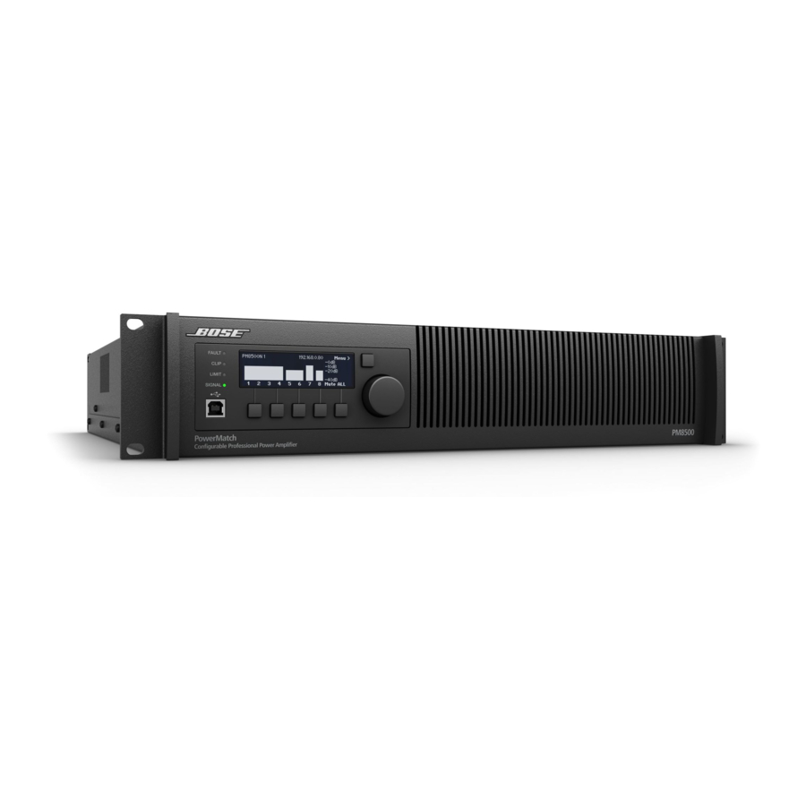
Installation and Operating Guide pro.Bose.com Controls, Display, and Connectors Figures 1 and 2 detail the various elements found on the front and rear panels of PowerMatch amplifiers. Figure 1. Front Panel View 1. LED Indicators 5. Menu Soft Keys (1-5) 2. -
Page 15: Hardware Installation
Accessory Kit PN PM8500, PM8500N 343511-0010 PM8250, PM8250N PM4500, PM4500N 343511-0020 PM4250, PM4250N Rack Mounting PowerMatch amplifiers are designed to fit standard 19-inch (48 cm) rack equipment, occupying 2 rack-units (RU) in height, requiring a mounting depth of 21 inches (53 cm) from the front rack rail. Use four fasteners with washers (not supplied) to mount the amplifier front panel rack ears to the equipment rack rails. -
Page 16: Making Connections
Installation and Operating Guide pro.Bose.com Making Connections Connection and Configuration Steps Use the following procedure when setting up a PowerMatch amplifier for the first time. ® 1. Install any digital expansion cards (optional) 2. Mount the amplifier into the rack 3. -
Page 17: Wiring Input Connectors
Installation and Operating Guide pro.Bose.com Wiring Input Connectors The balanced line-level analog inputs utilize 3-pin terminal block connectors (Phoenix Contact #1776168, supplied). Terminal descrip- tions are printed directly on the connectors for convenience. For balanced inputs, strip the wire ¼ inch (6 mm) and connect to the respective positive, negative, and ground terminals as indicated on the connector and in Figure 5. -
Page 18: Mono Mode
Note: While not optimal, a 70/100V loudspeaker load can be driven off a single channel in Mono mode but is limited to 50 V RMS / 71 V Peak capability. Download the application note "Using Mono Mode to Drive High Impedance Loudspeaker Loads" from pro.Bose.com for details on how to adjust software and tap settings for this derated use. -
Page 19: Fault Notification Output
Fault Output state when they occur. A full listing of the available protocol can be found in the PDF document "ControlSpace Serial Control Protocol" on pro.Bose.com. English... -
Page 20: Setup And Configuration
Installation and Operating Guide pro.Bose.com Setup and Configuration Figure 8 shows the basic signal flow and available DSP functions available to manipulate each individual input channel. Some functions and advanced parameters can only be modified using ControlSpace Designer™ software. See "Interface ®... -
Page 21: Control Panel Description
LED lights red when a fault condition has been detected. For more information see Figure 18, "Fault Conditions" on page 38. Clip LED Indicator Indicates red when the input signal reaches full scale. Bose recommends that you reduce input levels or modify input sensitivity settings to prevent this condition. (See Input Sensitivity on Page 24). -
Page 22: Front Panel Control Menu Structure
Installation and Operating Guide pro.Bose.com Front Panel Control Menu Structure The displays and user controls accessible by the front panel are presented in the following menu structure illustration: Figure 10. Front panel menu structure OPERATING Mute All MAIN MENU LEVEL... - Page 23 Installation and Operating Guide pro.Bose.com MAIN MENU ➞ MAIN MENU LEVEL METER CONFIG UTILITY Description The MAIN MENU offers five areas of control: • Level • Meter • DSP • Configuration • Utility Available Controls Navigation Soft Key: Back to OPERATING display.
- Page 24 Installation and Operating Guide pro.Bose.com MAIN MENU < LEVEL < INPUT SENS LEVEL Input Source ➞ Input Sensitivity Input Mute Output Mute Output Attenuate Description This display allows you to appropriately match each configured input channel to the incoming signal. This per channel setting corresponds to the level that will create rated power out of the amplifier, with all other gains through the DSP signal processing chain set to 0 dB (unity gain).
- Page 25 Installation and Operating Guide pro.Bose.com MAIN MENU < LEVEL < OUTPUT ATTEN LEVEL Input Source Input Sensitivity Input Mute Output Mute ➞ Output Attenuate Description This display allows you to attenuate each configured output channel. For channels set to output modes other than Mono, attenuation control is bound by the configured groupings.
- Page 26 Menu Soft Key #5: Enables the selection of the output channel (or output groupings) using the rotary encoder dial. Menu Soft Key #1: Enables users to select from a list of Bose speaker series, or none, using the rotary encoder. Once the desired series is highlight- ed, press the rotary encoder to select.
- Page 27 Installation and Operating Guide pro.Bose.com MAIN MENU < DSP < ARRAY EQ Speaker Presets ➞ Array EQ Delay Limiting Description This display allows you to apply additional EQ to each input channel that feeds signal to RoomMatch loudspeakers in array configurations.
- Page 28 MAIN MENU < DSP < SPEAKER PRESETS. ® For non-Bose loudspeakers, refer to manufacturer technical specifications for information to properly configure the limiter. See "Setting the Limiting Function for use with 3rd Party Loudspeakers" on page 34 for further details.
- Page 29 OFF, -60dB to 0dB in 1dB increments Notes Bose suggests that you first configure output modes (MAIN MENU < CONFIG < OUTPUT CONFIG) before performing input routing. MAIN MENU < CONFIGURE < OUTPUT CONFIG CONFIGURE ➞...
- Page 30 Installation and Operating Guide pro.Bose.com MAIN MENU < UTILITY ➞ UTILITY Standby mode Alarm Log Network Setup (Device ID) Lock Front Panel Set Front Panel Lock Combination Display Restore Factory Settings Firmware Version Description The UTILITY menu allows you to access additional configuration parameters of the amplifier.
- Page 31 IP Address Octet Values: 0 to 255 Notes DHCP is enabled by default on network version amplifiers. Upon Power Up, resolving of DHCP times out after 10 seconds to IP:80 for PM8500N/PM8250N and IP:40 for PM4500N/PM4250N. MAIN MENU < UTILITY < DEVICE ID (USB-only versions) UTILITY...
- Page 32 Installation and Operating Guide pro.Bose.com MAIN MENU < UTILITY < LOCK FRONT PANEL UTILITY Standby mode Alarm Log Network Setup (Device ID) ➞ Lock Front Panel Set Front Panel Lock Combination Display Restore Factory Settings Firmware Version Description This display allows you to view the current unlock combination and ability to lock the front panel controls to prevent tampering.
- Page 33 Restore Factory Settings Firmware Version Description This display allows you to view the model number, hardware software versions, installed Bose loudspeaker EQ presets file, and status of any plug-in cards. Available Controls To access the Firmware Versions menu, use the rotary encoder dial from the UTILITY menu to highlight, then press to select.
-
Page 34: Setting The Limiting Function For Use With 3Rd Party Loudspeakers
3. Select the proper EQ (flat or custom EQ for non-Bose loudspeakers) from MAIN MENU < DSP < SPEAKER PRESETS. 4. Using the manufacturer’s loudspeaker specification sheet, calculate the limiter RMS voltage using the loudspeaker's continuous power rating using the following formula: RMS Voltage = Square Root (rated power of the loudspeaker x loudspeaker impedance). -
Page 35: Sample Output Configurations For Different Loudspeaker Loads
RoomMatch 7010 array module loudspeakers (70° H x 10° V) ® (1) Bose PowerMatch PM4500 configurable professional power amplifier (PM8500 amplifier similar) Figure 12. RoomMatch two-module array configuration Note: All RoomMatch loudspeaker connections use Neutrik NL4 speakON-type cable connectors. Please refer to RoomMatch loudspeaker documentation for further details. -
Page 36: Maintenance Operations
To obtain the newest version of the Firmware and EQ files, download the latest version of ControlSpace Designer software from pro.Bose.com. Upon connection, you may be alerted of a newer version of firmware and/or EQ files and will be prompted for action. -
Page 37: Saving And Recalling Amplifier Settings (Usb-Only Version Amplifiers)
® ® become available. Check pro.Bose.com for updates and instructions on how to load and apply these files. Saving and Recalling Amplifier Settings (USB-only version amplifiers) You can save amplifier settings using a PC, USB connection, and ControlSpace Designer software. This may be useful for archiving settings made on the front panel after installation. -
Page 38: About The Alarm Log And Fault Indicator
Non-Customer Serviceable Warnings and Alarms Fault Text Resolution Both amp or PS fan fail Requires Bose Support. Call Bose Representative. Power supply fault ➟ ICV not OK power supply fault ➟ DC not OK power supply fault ➟ DC_200 not OK power supply fault ➟... -
Page 39: Troubleshooting
® Fault LED is lit Refer to Figure 18, "Fault Conditions" on page 38 for alarm conditions and potential solutions. Call your local Bose support contact for assistance with unlisted or unsolvable faults. USB is connected to PC but not found by •... -
Page 40: Appendix
Set output attenuation (dB) Set output mute View output gain (dB) View output voltage (V) Load Bose speaker EQ preset ® View Bose speaker EQ Load speaker array EQ Adjust delay Adjust limiting Modify output configuration Modify input routing Enter/exit standby mode... -
Page 41: Technical Specifications
< 0.95 ms Input to Output Signal Routing 8 x 8 matrix (PM8500 and PM8250), 4 x 4 matrix (PM4500 and PM4250) Loudspeaker Presets Bose Professional Input EQ 5-band PEQ (+/- 20 dB), notch, shelving, high pass, low pass Bandpass Filters (Crossover) - Page 42 Installation and Operating Guide pro.Bose.com Technical Specifications - PM8500 / PM8500N 2 Ω 4 Ω 8 Ω Power Rating 70 V 100 V THD for Power Rating, Typical < 0.1 % < 0.1% < 0.1% Mono Mode 500 W 500 W...
- Page 43 Installation and Operating Guide pro.Bose.com Technical Specifications - PM8250 / PM8250N 2 Ω 4 Ω 8 Ω Power Rating 70 V 100 V THD for Power Rating, Typical < 0.1 % < 0.1% < 0.1% Mono Mode 250 W 250 W...
- Page 44 Installation and Operating Guide pro.Bose.com Technical Specifications - PM4500 / PM4500N 2 Ω 4 Ω 8 Ω Power Rating 70 V 100 V THD for Power Rating, Typical < 0.1 % < 0.1% < 0.1% Mono Mode 500 W 500 W...
- Page 45 Installation and Operating Guide pro.Bose.com Technical Specifications - PM4250 / PM4250N 2 Ω 4 Ω 8 Ω Power Rating 70 V 100 V THD for Power Rating, Typical < 0.1 % < 0.1% < 0.1% Mono Mode 250 W 250 W...
-
Page 46: Ac Current Draw And Thermal Dissipation Information
4Ω/Ch Mono 6dB Crest Factor 2Ω/Ch I-Share 1,333 14.9 1,553 8Ω/Ch V-Bridge 4Ω/Ch Quad PM8250 / PM8250N, AC Current Draw and Thermal Dissipation Thermal Dissipation, Typical 120VAC 60Hz. 230VAC 50Hz. Load Configuration Total Audio Typical Line Typical Line Test Signal & Power Level... - Page 47 Installation and Operating Guide pro.Bose.com PM4250 / PM4250N, AC Current Draw and Thermal Dissipation Thermal Dissipation, Typical 120VAC 60Hz. 230VAC 50Hz. Load Configuration Total Audio Typical Line Typical Line Test Signal & Power Level (All Channels Driven) Output, W Current, A...
- Page 48 Installation and Operating Guide pro.Bose.com Page 48 User Guide English...
-
Page 49: English User Guide
Installation and Operating Guide pro.Bose.com English User Guide Page 49... - Page 50 Installation and Operating Guide pro.Bose.com Page 50 User Guide English...
-
Page 51: Additional Resources
Additional Resources pro.Bose.com Additional Resources Visit us on the web at pro.Bose.com for more information, including specifications, technical literature, product warranty, parts and accessories, and global support contact information. Americas Hong Kong (USA, Canada, Mexico, Central America, South America) Bose Limited... - Page 52 © 2013 Bose Corporation. All rights reserved. The Mountain, Framingham, MA 01701-9168 USA www.pro.Bose.com All trademarks are the property of their respective owners. AM364052 Rev. 00...
Need help?
Do you have a question about the PowerMatch PM8250N and is the answer not in the manual?
Questions and answers