
Related Manuals for Clarke weld MIG 151EN


Summary of Contents for Clarke weld MIG 151EN
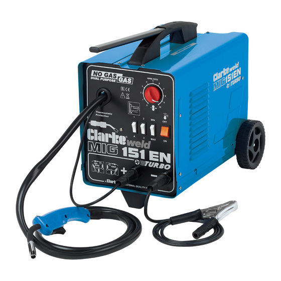
- Page 1 GAS/NO-GAS MIG WELDER GAS/NO-GAS MIG WELDER Models 90EN, 100EN, 105EN & 151EN 0515 OPERATING & MAINTENANCE INSTRUCTIONS...
-
Page 2: Guarantee
CLARKE MIG Welder, designed to operate with or without gas..so-called GAS/NO-GAS welders. This is explained in greater detail within the manual. Before attempting to operate the machine, it is essential that you read this manual thoroughly and carefully follow all instructions given. -
Page 3: Table Of Contents
CONTENTS PAGE Guarantee ....................3 Parts & Service Contacts ..............3 Electromagnetic Interference (EMC) ..........4 Safety Precautions ................. 6 Additional Safety Precautions for MIG Welding ....... 11 Principles of Operation ............... 12 Electrical Connections ............... 13 Unpacking and Parts Identification ........... 14 Assembly ....... -
Page 4: Electromagnetic Interference (Emc)
ELECTROMAGNETIC INTERFERENCE (EMC) Whilst this unit complies with EMC regulations, the user is responsible for installing and using the welding equipment according to the manufacturers instructions. If electromagnetic disturbances are detected then it shall be the responsibility of the user of the welding equipment to resolve the situation. In some cases this remedial action may be as simple as earthing the welding circuit, see ‘Note’. - Page 5 take additional precautions such as filtering of the mains supply. Consideration should be given to shielding the supply cable of permanently installed welding equipment, in metallic conduit or equivalent. Shielding should be electrically continuous throughout its length. The shielding should be connected to the welding power source so that good electrical contact is maintained between the conduit and the welding power source enclosure.
-
Page 6: Safety Precautions
SAFETY PRECAUTIONS FOR ALL TYPES OF WELDING 1. WARNING: As with all machinery, there are certain hazards involved with their operation and use. Exercising respect and caution will considerably lessen the risk of personal injury. However, if normal safety precautions are overlooked, or ignored, personal injury to the operator may result. - Page 7 C) Fire and explosion prevention Causes of fire and explosion are: 1) combustibles reached by the arc, flame, flying sparks, hot slag or heated material; 2) misuse of compressed gases and cylinders; 3) short circuits. BE AWARE THAT flying sparks or falling slag can pass through cracks, along pipes, through windows or doors, and through wall or floor openings, out of sight of the goggled operator.
- Page 8 3. ELECTRIC ARC (MIG, TIG) WELDING Comply with precautions in 1 above, and this section. Arc welding, properly done, is a safe process, but a careless operator invites trouble. The equipment carries high currents at significant voltages. The arc is very bright and hot. Sparks fly, fumes rise, ultraviolet and infrared energy radiates, weldments are hot.
- Page 9 3C) FIRE AND EXPLOSION PREVENTION Comply with precautions in 2C. Equipment’s rated capacity. Do not overload arc welding equipment. It may overheat cables and cause a fire. Loose cable connections may overheat or flash and cause a fire. Never strike an arc on a cylinder or other pressure vessel.
- Page 10 4) Cables Frequently inspect cables for wear, cracks and damage. IMMEDIATELY REPLACE those with excessively worn or damaged insulation to avoid possibly lethal shock from bared cable. Cables with damaged areas may be taped to give resistance equivalent to original cable. Keep cable dry, free of oil and grease, and protected from hot metal and sparks.
-
Page 11: Additional Safety Precautions For Mig Welding
NEVER attempt any electrical or mechanical repair unless your are a qualified technician. If you have a problem with the machine contact your local CLARKE dealer. • NEVER use or store in a wet/damp environment. DO NOT EXPOSE TO RAIN. -
Page 12: Principles Of Operation
SAFETY EQUIPMENT A comprehensive range of CLARKE safety equipment for use when welding is available from your local dealer. NO-GAS MIG WELDING - PRINCIPLES OF OPERATION MIG (Metal Inert Gas) welding is a process in which a power wire electrode is fed continuously into the weld pool at a controlled, constant rate. -
Page 13: Electrical Connections
ELECTRICAL CONNECTIONS WARNING! THIS APPLIANCE MUST BE EARTHED. These welders are fitted with a standard 13 amp BS 1363 plug, fitted with a 13 amp fuse. Connect to a 230 volt (50Hz) domestic electrical supply and we strongly recommend that this be done via a Residual Current Device (RCD). IMPORTANT: If the welder is fitted with a plug which is moulded onto the electric cable (i.e. -
Page 14: Unpacking And Parts Identification
UNPACKING & PARTS IDENTIFICATION Unpack and lay out the components, checking against the following list. Any damage or deficiency should be reported to your CLARKE dealer immediately. Most of the components are stored within the side compartment. To open the compartment, pull the side panel up sharply. -
Page 15: Assembly
ASSEMBLY & INSTALLATION A. LOOSE COMPONENTS MIG’s, 90EN, 100EN & 105EN Lay the welder gently on its side and attach the four feet using the screws and flat washers provided. MIG 151EN only Insert the axle through the holes in the rear base of the machine, then attach the wheels, securing them by pushing the star locking washers provided, on to the axle, using a piece of tube or an old socket, ensuring the centre tines of the washer face outwards. -
Page 16: Installing The Welding Wire
C. INSTALLING THE WELDING WIRE NOTE: These machines are supplied with a Clarke ‘Mini’ spool of mild steel flux cored welding wire. A 5kg spool is available from your Clarke dealer. See ‘Accessories’ for full details. IMPORTANT: Ensure that theelectrical supply is disconnected. - Page 17 IMPORTANT! If you are changing the size of wire, you must also select the appropriate groove on the feed roller. See p. 19 Fig.5 Re: Fig.5 Pull out the end of the wire from the rim of the spool, taking care NOT to release it. The spool is wound firmly and should remain this way.
-
Page 18: Selecting The Drive Roller Groove
(3) Selecting the Correct Drive Roller Groove As previously mentioned, it is important that the correct groove in the drive roller is selected for the particular wire being used. Two grooves, 7mm and 9mm are provided. The 7mm groove should be used with 6mm dia. wire and the 9mm groove for all 8mm wire and 9mm flux cored wire. - Page 19 Always use the appropriate gas for the material being welded. Three types are provided by Clarke International, as follows: Carbon Dioxide (CO ) ..For Mild Steel ....Part No. 6000642 Argon ........For Aluminium ....Part No. 6000661 CO2/Argon Mix ....For Thin Sheet metal Mild Steel/ Stainless ..
-
Page 20: Preparation For Use
PREPARATION FOR USE PREPARE THE WORK MOST IMPORTANT! It is VITAL that the workpiece is perfectly clean at the point of weld. Any coating, plating or corrosion MUST be removed, otherwise a good weld will be impossible to achieve. B. SET THE CONTROLS Fig.10 In order to produce a satisfactory... -
Page 21: Welding Wire Preparation
Models 90EN, 1010EN and 105EN are provided with two, 2-position switches marked 1- 2 and MAX - MIN respectively, as shown in Fig 10. Model 150EN is provided with three 2-position switches, marked A-1, 2-3 and MAX-MIN. These controls areused to control the welding current according to the type and thickness ofmaterial to be welded, and in accordance with the charts shown in the‘Reference Tables’... -
Page 22: Mig Welding Operation
OPERATION With the welding current set, and welding wire trimmed, set the wire feed control to 6 , (8 for Aluminium). Plug the machine into the mains supply or switch on at the isolator and ensuring all precautions have been taken and with the machine set up correctly, lower the torch to the workpiece with one hand, whilst holding the welding mask in the other. -
Page 23: Welding Tips
Replacement clear and dark lenses are available from your Clarke dealer - see Parts Lists for details. NEVER use any dark filter lens other than that provided by CLARKE International, or one with the same certified ‘Optical class’... -
Page 24: Renewing The Wire Liner
RENEWING THE WIRE LINER Fig.12 If the liner becomes damaged or kinked, it will be necessary to replace it. Before commencing work, ensure the electrical supplies disconnected. Open the side cover, and remove the welding wire from the hose and torch assembly. (Refer to ‘Installing Welding Wire’... -
Page 25: Troubleshooting
TROUBLESHOOTING Your Clarke Mig Welder has been designed to give long and trouble free service. If, however, having followed the instructions in this booklet carefully, you still encounter problems, the following points should help identify and resolve them. PROBLEM CAUSE REMEDY 1. -
Page 26: Control Settings Reference Tables
CONTROL SETTINGS - REFERENCE TABLES A. MIG 90EN STEEL 0.6 mm Gas Welding Wire 0.8 mm Gas Welding Wire Workpiece Welding Wire Speed Welding Wire Speed Thickness Position Position Adjustment Adjustment (mm) 0.6 - 0.8 0.8 - 1.0 1.0 - 2.0 2.0 - 3.0 ALUMINIUM 0.8 mm Gas Welding Wire... - Page 27 CONTROL SETTINGS - REFERENCE TABLES B. MIGs 100EN & 105EN STEEL 0.6 mm Gas Welding Wire 0.8 mm Gas Welding Wire Workpiece Welding Welding Wire Speed Wire Speed Thickness Position Position Adjustment Adjustment (mm) 0.6 - 0.8 0.8 - 1.0 1.0 - 2.0 2.0 - 3.0 >3.0...
- Page 28 CONTROL SETTINGS - REFERENCE TABLES B. MIGs 151EN STEEL 0.6 mm Gas Welding Wire 0.8 mm Gas Welding Wire Workpiece Welding Welding Wire Speed Wire Speed Thickness Position Position Adjustment Adjustment (mm) 0.5 - 0.6 0.6 - 0.8 0.8- -1.0 2/3 MAX 2/3 MAX 1.0 - 1.2...
-
Page 29: Wiring Diagrams
WIRING DIAGRAMS MIG 90EN... - Page 30 WIRING DIAGRAMS MIG 100EN & 105EN...
- Page 31 WIRING DIAGRAMS MIG 151EN...
-
Page 32: Parts Lists And Diagrams
PARTS DIAGRAM - MIG 90EN... - Page 33 PARTS LIST - MIG90EN Part No. No. Description P.C. Board EN22710043 Handle EN21600035 Wire Feeding Motor l 2V EN04600143 Rectifier EN22400001 Complete Thermostat EN04600126 Cable Clamp EN04600233 Torch Grommet On Front Panel EN21690458 FrontPdnel EN33710056 Potentiometer Knob EN04600333 Amber Pilot-light Switch EN22200022 Input Cable EN20220068...
- Page 34 PARTS DIAGRAM - MIG 100EN & 105EN...
- Page 35 PARTS LIST - MIG100EN & 105EN Part No. No. Description P.C. Board EM22710043 Handle EM21600035 Wire Feeding Motor EM22810001 Rectifier EM22400001 Complete Fan EM04600055 Cable Clamp EM21605010 Front Panel EM33710056 Welding Current Switch EM22200038 Potentiometer Knob EM21690310 Input Cable EM20220068 Flux-cored Wire Spool See Accessories Spool Holder Retaining Ring...
- Page 36 PARTS DIAGRAM - MIG 151TE...
- Page 37 PARTS LIST - MIG151TE Part No. No. Description Part No Handle-Extension EN33725071 9005 P.C. Board EN22710043 Handle EN 21600035 Wire Feeding Motor EN 04600143 Complete Thermostat EN 04600126 Complete Fan EN 04600055 Cable Clamp EN4600233 Front Panel Black EN33710056 9005 High/Low Power Switch EN 22200038 Red Knob...
-
Page 38: Accessories
8132040 4. Gas Regulator 8132000 In addition to the above, your Clarke dealer can provide you with a wide range of welding accessories, safety equipment etc., to increase productivity where necessary and to simplify and assist in the welding process. -
Page 39: Welder Specifications
6 minutes and must have a down time of 4 minutes. Please note that the details and specifications contained herein, are correct at the time of going to print. However, CLARKE International reserve the right to change specifications at any time without prior notice.
Need help?
Do you have a question about the weld MIG 151EN and is the answer not in the manual?
Questions and answers