
Subscribe to Our Youtube Channel
Related Manuals for IOGear M1123


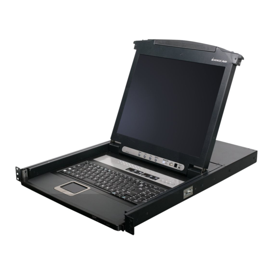
Summary of Contents for IOGear M1123
- Page 1 Installation Guide Installation 8/16-Port 17” LCD Combo KVM Switch GCL1808/GCL1816 PART NO. M1123/M1124...
- Page 2 All information furnished here is for informational purposes only and is subject to change without notice. IOGEAR, Inc. assumes no responsibility for any inaccuracies or errors that may appear in this document.
-
Page 3: Table Of Contents
Table of Contents On-screen Display (OSD) Operation Package Contents Hotkey Setting Mode (HSM) System Requirements Mac Keyboard Emulation Overview Sun Keyboard Emulation Rack Mounting Factory Default Settings Grounding Firmware Upgrade Open/Close Console Upgrade Fail Single Level Installation Restore Factory Default Settings 2-Level Installation (Cascading) Safety Instructions External Console Port (Optional) -
Page 4: Package Contents
Package Contents - 1 x 8/16-Port LCD KVM - 1 x PS/2 KVM Cable - 1 x USB KVM Cable - 1 x Console Cable - 1 x Firmware Upgrade Cable - 1 x Rack Mount Kit (Long and Short L Brackets) - 1 x Grounding Wire - 1 x Power Cord - 1 x Installation Guide... -
Page 5: System Requirements
System Requirements Computers • VGA, SVGA, or MultiSync video graphics card with an HDB-15 port • PS/2 mouse and keyboard ports (6-pin mini DIN) or 1 USB port... -
Page 6: Overview
Overview Slide Release Handle Bar LCD Display LCD Power Button LCD Controls Port LEDs (8 for GCL1808 and 16 for GCL1816) Keyboard Touchpad External USB Mouse Port Power LED Master/Slave Port Switches Num Lock/Caps Lock/Scroll Lock LED Reset Button Firmware Upgrade Recovery Switch Firmware Upgrade Port USB Sharing Port Front view... - Page 7 Grounding Terminal Power Socket Power Switch External Console Port CPU Ports (8 for GCL1808 and 16 for GCL1816) PS/2-USB PS/2-USB CONSOLE Back view...
-
Page 8: Rack Mounting
Rack Mounting The following diagram shows the required components to mount the LCD KVM to the rack. L Bracket CAUTION: Slide/rail Side Mounting Brackets mounted equipment is not to be used as a shelf or a work space. Note: The Slide Mounting Brackets are pre-installed onto the LCD KVM. - Page 9 Step 1 While one person holding the LCD KVM in the proper position in the rack, the second person can lock the screws loosely through the front bracket onto the front of the rack. M4 x 6 Phillips Head Screws...
- Page 10 Step 2 While the person continue holding the position of M4 x 6 Phillips the LCD KVM, the second person can slide the L Head Screws brackets from the back of the rack into the Slide Mounting Brackets. Then, you can lock the screws through the rear bracket onto the back of the rack.
-
Page 11: Grounding
Grounding To prevent damaging your equipment, it is important that all devices are properly grounded. Use the included grounding wire to ground the LCD KVM by connecting one end of the wire to the grounding terminal, and the other end of the wire to a suitable grounded object. PS/2-USB PS/2-USB CONSOLE... -
Page 12: Open/Close Console
Open/Close Console Opening the Console Slide the 2 Slide Releases toward the center of the LCD KVM, then pull the console module out while holding the Slide Releases’ position. Then simply open the console by raising the handle bar. - Page 13 Closing the Console First, close the LCD module with the handle bar, then pull the safety catches on both sides of the console module towards yourself to release the safety lock. Then slide the 2 Slide Releases toward the center of the LCD KVM, then push the console module all the way in while holding the Slide Releases’...
-
Page 14: Single Level Installation
Single Level Installation Please make sure the computers are powered off before you start. Step 1 Connect the power cord to the power outlet and the power socket of the LCD KVM. PS/2-USB PS/2-USB CONSOLE... - Page 15 Step2 Connect a USB KVM Cable (with a green connector) or PS/2 KVM Cable (with a yellow connector) from the KVM switch to each of your computers PS/2-USB PS/2-USB CONSOLE USB KVM Cable PS/2 KVM Cable Connection Connection...
- Page 16 Step 3 Turn on LCD KVM by using the power switch that’s located in the back of the LCD KVM. PS/2-USB PS/2-USB CONSOLE Final Step Turn on your computers.
-
Page 17: 2-Level Installation (Cascading)
2-Level Installation (Cascading) This LCD KVM can be cascaded with our GCS1808/GCS1716. Please go to our website at www.iogear.com for details about those 2 KVMs. Please make sure the computers are powered off before you start. Step 1 Connect the power cord to the power outlet and the power socket of the LCD KVM. Then connect the power adapter to the power outlet and the DC jack of the GCS1808/GCS1716. - Page 18 Step 2 Connect the Cascade Cable between the back of the LCD KVM and a GCS1808/GCS1716. Connect the green connector to one of the CPU ports from the LCD KVM. Then, connect the yellow connector to the console port of the GCS1808/GCS1716. PS/2-USB PS/2-USB CONSOLE...
- Page 19 Step 3 Connect a USB KVM Cable (with a green connector) or PS/2 KVM Cable (with a yellow connector) from the KVM switch to each of your computers. CONSOLE PS/2-USB 2nd Level...
- Page 20 USB KVM Cable Connection PS/2 KVM Cable Connection Step 4 Turn on LCD KVM by using the power switch that’s located in the back of the LCD KVM. Final Step Turn on your computers.
-
Page 21: External Console Port (Optional)
External Console Port (Optional) If you wish to use external monitor, keyboard or mouse rather then the built-in LCD, keyboard or touchpad, you can connect the console cable to the external console port in the back of the LCD KVM. Then, connect your external VGA monitor, USB or PS/2 keyboard and mouse to the console cable. -
Page 22: Usb External Mouse Port (Optional)
USB External Mouse Port (Optional) There is an external mouse port in the front of the LCD KVM next to the Power LED. Simply plug in any USB connection of the mouse to that USB port to use an external mouse instead of the touchpad. -
Page 23: Usb Sharing Port
USB Sharing Port The USB sharing port is located below the LCD display and next to the firmware upgrade port. This USB port allows you to share a USB device ONLY for the computers that are connected to the LCD KVM via USB KVM Cable (The green connector KVM cable). -
Page 24: Lcd Configuration
LCD Configuration There are four buttons for LCD configuration, the functions are as follow: Button Function Menu • If you are currently not in the LCD OSD (On Screen Display) Menu, press this Menu button will bring up the LCD OSD Menu. •... -
Page 25: Lcd Adjustment Setting
LCD Adjustment Setting There are ten functions in the LCD OSD Menu, and they are as follow: Setting Function Brightness This function adjusts the brightness of the LCD Contrast This function is to eliminate pixel jitters or horizontal line noise Phase This function is to eliminate vertical banding Clock... -
Page 26: Reset Button
Reset Button Use a paper clip or any kind of small object to press the reset button, you will then hear a beep sound which indicates that it will perform a system reset on the LCD KVM. -
Page 27: Led Indication
LED Indication Description No LED No computer is connected to the specific port or the computer is connected to the specific port but it is not powered on Orange The specific port has a computer connected and it is powered on... -
Page 28: Keyboard Function Keys
Keyboard Function Keys There are 6 sets of Keyboard Function Keys on the built-in keyboard and they are as follow. Simply Hold the [Fn] key then press the function key and release the [Fn] key to trigger the specific function. Function Description Mute key... -
Page 29: Port Switching
Port Switching Port Switching via Port Switches If you wish to switch to a port that’s on the 1st level, simply press the up or down button to select the Master Port ID If you wish to switch to a port that is on the 2nd level, first, press the up or down button to select Master port ID for the port on the 1st level that is connected to the desire 2nd level’s port. -
Page 30: On-Screen Display (Osd) Operation
On-screen Display (OSD) Operation Trigger OSD OSD Main Screen Simply press [Scroll Lock] [Scroll Lock] rapidly. When you invoke the OSD, a screen similar to the one below appears: Note: This hotkey sequence can be changed to [Ctrl] [Ctrl]. Please refer to Hotkey Setting Mode (HSM) section. - Page 31 Notes: The diagram depicts the administrator’s main screen. The user main screen does not show the F4 and F6 functions, since these are reserved for the administrator and can’t be accessed by users. The OSD always starts in list view, with the highlight bar at the same position it was in the last time it was closed.
- Page 32 OSD Main Screen Headings Heading Description This column lists the port ID numbers for all the KVM ports on the installation. The simplest method to access a particular computer is move the highlight bar to it then press Enter. QV If a port is selected for quick view scanning an arrowhead shows in this column.
- Page 33 OSD Navigation • After executing any action, you automatically • To dismiss the menu, and deactivate OSD, go back to the menu one level above. click the X in the upper right corner of the OSD window; or press [Esc]. OSD Function •...
- Page 34 F1: GOTO F1: GOTO If [1] was chosen, then type in the port’s name that This function is to let you switch to a specific port you want to go to and then press [Enter]. You can via port ID or port’s name. Enter [1] to choose from also move the red highlight bar to the specific port Port Name and [2] to choose from Port Number in that you want to go to and press [Enter].
- Page 35 F2: LIST If [2] was chosen then you can go to a specific port F2: LIST by entering the port ID. You can also move the red This function allows you to choose a way that you highlight bar to the specific port that you want to wish to list the ports in the OSD display on the go to and press [Enter].
- Page 36 Function Description List out all ports that the administrator has set as accessible for the current logged in user Quick View List out only the ports that have been set as quick view ports Powered ON List out only the ports that have been powered on Quick View + Pow- List out only the ports that have been set as quick view ports and they have ered ON...
- Page 37 F3: SET F3: SET OSD Hotkey There are 11 different settings within the SET This function allows you to switch the way to section, which they are as follow: trigger the hotkey between [Scroll Lock] [Scroll Lock] and [Ctrl] [Ctrl]. Simply move the red OSD Hotkey highlight bar to the hotkey setting that you would Port ID Display Position...
- Page 38 Port ID Display Position Port ID Display Duration This function allows you to change the position This function allows you to change the port ID of the port ID that’s showing on the screen as the display duration between 3 seconds and off. image below.
- Page 39 Scan Duration Port ID Display Mode This function allows you to set the autoscan time This function allow you to choose the way you interval between 0 second to 255 seconds (5 want to show the ports in the OSD main screen – second is set by default).
- Page 40 Scan-Skip Mode This function allows you to set the behavior in autoscan mode. Simply move the red highlight bar to the behavior you want and press [Enter]. Then, press [Esc] to exit from this function. Function Description Scan all ports that the administrator has set as accessible for the current logged in user...
- Page 41 Screen Blanker Hotkey Command Mode This function allows you to set the time interval to This function allows you to enable or disable the have the KVM goes to a black screen. Simply en- hotkey commands. Simply press Y for yes and N ter the number between 0 to 30 and press [Enter];...
- Page 42 OSD Language Hotkey This function allows you to choose the OSD This function allows you to set the hotkey language between English, Deutsch, Japanese, sequence that you wish to use to trigger hotkeys Simplified Chinese and Traditional Chinese. Simply commands. Simply move the red high light bar to move the red high light bar to the language that choose the sequence that you wish to use and youwish to choose and press [Enter].
- Page 43 Touchpad This function allows you to enable/disable the touchpad. It will ask if you want to enable the touchpad or disable the touchpad depending on the current status of it. Simply press Y for yes and N for no.
- Page 44 F4: ADM F4: ADM Set User Login This function will only be shown if you have login This function allows you to setup the login name as Administrator. There are 12 different functions and password for the users accounts. There are within the ADM section, which they are as follow: 5 user accounts in the system –...
- Page 45 Then simply type in the user name and Once the user name and password are set password. Then, enter the password again for correctly, you will see the message in the bottom of confirmation then press [Enter]. (We have used the the screen indicating the setup is ok.
- Page 46 Set Accessible Ports This function allows you to setup the access on each port for each user. Use [Spacebar] to cycle through all the entries and press [Enter] to complete the setup. Then, press [Esc] to exit from the function. Function Description F (Full)
- Page 47 Set Logout Timeout Edit Port Names This function allows you to set a time that the KVM This function allows you to customize a name will automatically logout after being idle for a certain on each port of the KVM. Simply move the red period of time.
- Page 48 Restore Default Values Enter the port name that you wish to show in OSD This function allows you to restore all settings into for that specific port and press [Enter] to complete factory default settings. Move the red highlight the editing. Then, press [Esc] to exit from this bar to Restore Default Values and press [Enter].
- Page 49 Activate Beeper Clear The Name List This function allows you to enable or disable the This function allows you to clear up all the port beeper sound while switching port. Move the red names to blanks. Move the red highlight bar to highlight bar to Activate Beeper and press [Enter].
- Page 50 Set Quick View Ports This function allows you to set the desire ports as Quick View Ports. If a port is selected as a Quick View Port, an icon will show in the QV column of the OSD main screen. Simply more the red highlight bar to the desire port and press [Spacebar] to select the port as a Quick View Port.
- Page 51 Set Operating System This function allows you to define what kind of operating system is being used in each port. Simply move the red highlight bar to the desire port and press [Spacebar] to cycle through the options between WIN, MAC, SUN or OTHER. Note: The keyboard Operating platform will changed accordingly depending what you have chosen in this function.
- Page 52 Firmware Upgrade After you type Y, you will see the below screen. This function allows you to have the KVM activates The KVM is now in firmware upgrade mode. the firmware upgrade mode so that you can Please see Firmware Upgrade section for details perform a firmware upgrade to the KVM.
- Page 53 Set Console Mode Keyboard Language This function allows you to selects which console This function allows you to choose the keyboard language of your console keyboard. Auto is chosen to be enabled. [0] is to enable both Internal Console and optional External Console, [1] is to by default;...
- Page 54 F5: SKP F5: SKP Function Description This function allows you to trigger Skip Mode. Simply press [F5] to activate skip mode. When [←] Switch to the last accessible port you see a left and right arrow next to the port number as the image below, you can press the [→] Switch to the next accessible port...
- Page 55 F6: BRC / F7: SCAN F6: BRC F7: SCAN This function will only be shown if you have login This function allows you to autoscan all the as Administrator. Simply press [F6] to trigger available ports. (This autoscan behavior depends Broadcast (BRC) Mode, then you will see a on the Scan-Skip Mode and Scan Duration.) speaker symbol next to the port number.
- Page 56 F8: LOUT F8: LOUT This function allows you to logout of the OSD. So, when another person is trying to access this from the console, he would have to login again. Simply Press Y to proceed the logout and N to cancel.
-
Page 57: Hotkey Setting Mode (Hsm)
Hotkey Setting Mode (HSM) Function Description Press and hold [Num Lock] Invoking hotkey setting mode Press and release [-] Release [Num Lock] Note: To exit HSM manually, press Esc or spacebar. Press [KVM Hotkey] Button that is located on the left bottom corner of the built-in keyboard. - Page 58 Invoke HSM, then press [F5] Perform keyboard / Mouse reset on the port that has KVM focus. Note: You can also press and hold Port 1 and Port 2 front panel push button to perform keyboard / mouse reset. Invoke HSM, then press [←] Invokes Skip mode and skips from the current port to the first accessible port previous to it Invoke HSM, then press [→]...
- Page 59 Invoke HSM, then press [b] Toggle hotkey beepers on or off Invoke HSM, then press [X*] [Y*] Switches KVM focus to the computer that is connected to [Enter] Port X in the 1st Level and Port Y in the 2nd Level Note: If you only have a single level installation, simply ignore the Y interval Invoke HSM, then press [r] [Enter]...
-
Page 60: Mac Keyboard Emulation
Mac Keyboard Emulation The PC compatible (101/104 key) keyboard can emulate the functions of the Mac keyboard. The emulation mappings are listed in the table below. PC Keyboard Mac Keyboard [Alt] [Shift] Shift [Print Screen] [Crtl] Ctrl [Scroll Lock] [Ctrl] [1] [Enter] Return... -
Page 61: Sun Keyboard Emulation
Sun Keyboard Emulation The PC compatible (101/104 key) keyboard can emulate the functions of the Sun keyboard. The emulation mappings are listed in the table below. [Ctrl] [F9] Find PC Keyboard Sun Keyboard [Crtl] [F10] [Crtl] [t] Stop [Crtl] [F2] Again [Crtl] [1] [Crtl] [2]... -
Page 62: Factory Default Settings
Factory Default Settings Function Default Settings OSD Hotkey [Scroll Lock] [Scroll Lock] Invoking HSM [Num Lock] [-] Auto Scan Duration 5 seconds Scan-Skip Mode Screen Blanker Beeper Keyboard Operating Platform PC Compatible Port ID Display Position Upper left corner Port ID Display Duration 3 seconds Port ID Display Mode Port Number + Port Name... -
Page 63: Firmware Upgrade
Step 3 nected to the LCD KVM. Go to www.iogear.com from the computer that performing the firmware upgrade to download the Step 1 latest available firmware or the specific firmware Connect the provided firmware upgrade cable to that you wish to upgrade to. - Page 64 Step 6 Step 7 Read the License Agreement and click “I Agree” Choose the correct KVM* that you wish to perform firmware upgrade from the “Device List” and then then click “Next” if you wish to continue with the firmware upgrade. Otherwise, click “Cancel” to exit click “Next”...
- Page 65 Step 8 Step 9 If you have checked the “Check Firmware Version” Warning window may popup again for 2nd part of checkbox, then the utility will check the current the firmware upgrade (IO1). firmware that is on your KVM. If the current firmware is newer than the firmware that you wish to upgrade to, a window will popup and prompt you to ask if you wish to proceed.
- Page 66 Step 12 Step 11 When the firmware upgrade is done, you will see When the firmware upgrade is done, you will see “Firmware upgrade OK” in the “Status Messages” “Firmware upgrade OK” in the “Status Messages” window. Then simply click “Finish” to complete the window.
-
Page 67: Upgrade Fail
Upgrade Fail Step 3 If you don’t see “Firmware upgrade OK” in the Repeat the firmware upgrade process. (Please refer “Status Messages” window, it means the utility has to Firmware Upgrade section) failed to complete the firmware successfully. If that occurs, please do the following: Step 4 After the firmware upgrade has completed, turn off... -
Page 68: Restore Factory Default Settings
Restore Factory Default Settings This restore will change all settings back to default. This will also have administrator and all user accounts removed from the LCD KVM. All port names and setting will also be removed. In other words, everything will be changed as if it is a brand new unit. - Page 69 Step 5 Step 7 Now plug the power cord back to the power sock- Turn off the LCD KVM and unplug the power cord et and turn the LCD KVM back on. This will restore from the power socket, then remove the jumper the LCD KVM with the factory default settings.
-
Page 70: Safety Instructions
Safety Instructions General • Please read all of these instructions and save them for future reference. • Carefully follow all warning and instructions marked on the device. • Do not place the device on any unstable surface (cart, stand, table, etc.). If the device falls, serious damage may result. - Page 71 • In order to prevent damage once installed, it is important that this device and all devices connected to it are properly grounded. • As a safety feature, the device is equipped with a 3-wire grounding plug. If you are unable to insert the plug into an outlet, please contact an electrician to repair/replace the outlet.
- Page 72 • If the following conditions occur, unplug the device from the wall outlet and bring it to qualified service personnel for repair: - The power cord or plug is damaged or frayed; - Liquid was spilled into the device; - The device was exposed to rain or water - The device was dropped, or the cabinet was damaged;...
- Page 73 Rack Mounting • Before working on the rack, make sure that the stabilizers are secured to the rack, extended to the floor, and that the full weight of the rack rests on the floor. Install front and side stabilizers on a single rack or front stabilizers for joined multiple racks before working on the rack.
-
Page 74: Specifications
Specifications Model GCL1808 GCL1816 Power Consumption Physical Housing Metal + Plastic Properties Weight 27.78lb 29.03lb Dimension (W x H x D) 17in. x 1.75in. x 25in. Environment Operating Temperature 0-40˚C Storage Temperature -20-60˚C Humidity 0-80% RH; Noncondensing... -
Page 75: Federal Communications Commission (Fcc) Statement
Federal Communications Commission (FCC) Statement This product has been tested and found to comply with the limits for a Class A digital device, pursuant to Part 15 of the FCC Rules. These limits are designed to provide reasonable protection against harmful interference when the equipment is operated in a commercial environment. -
Page 76: Ce Statement
CE Statement This device has been tested and found to comply with the requirements set up in the council directive on the approximation of the law of member states relating to EMC Directive 89/336/EEC, Low Voltage Directive 73/23/EEC and R&TTE Directive 99/5/EC. The product has been approved for LVD and covered the following countries: Belgium, Denmark, France, Germany, Italy, Portugal, U.K., Spain, Sweden... -
Page 77: Sj/T 11364-2006
SJ/T 11364-2006 The following contains information that relates to China. 有毒有害物质或元素 部件名称 多溴联苯 多溴二苯醚 铅 (Pb) 汞 (Hg) 镉(Cd) 六价 (Cr(VI)) (PBB) (PBDE) 电器部件 ● ○ ○ ○ ○ ○ 机构部件 ○ ○ ○ ○ ○ ○ ○:表示该有毒有害物质在该部件所有均质材料中的含量均在SJ/T 11363-2006规定的限量要求之下。 ●:表示符合欧盟的豁免条款,但该有毒有害物质至少在该部件的某一均质材料中的含量超出 SJ/T 11363-2006的限量要求。... -
Page 78: Limited Warranty
For further inquiries please contact IOGEAR. -
Page 79: Contact
Contact IOGEAR 19641 Da Vinci Irvine, CA 92610 P 949.453.8782 F 949.453.8785 Visit us at: www.iogear.com... - Page 80 About Us About Us IOGEAR offers connectivity solutions that are innovative, fun, and stylish, helping people enjoy daily life using our high technology products. GREEN IOGEAR is an environmentally conscious company that emphasizes the importance of conserving natural resources. The use of our technology solutions helps reduce electronic waste.
Need help?
Do you have a question about the M1123 and is the answer not in the manual?
Questions and answers