Advertisement
Quick Links
INSTALLATION INSTRUCTIONS FOR BLOWER KIT FBK-250 (CATALOG NO. 80L86)
GENERAL INFORMATION
This blower kit may be used with gas fireplaces. The FBK-250 blower kit
is used when unit-mounted variable speed blower control is desired. The
blower is installed beneath the firebox. Room air is drawn in through the
bottom area of the fireplace, heated as it passes across the firebox, and
discharged through the upper panel/louver area at the top of the
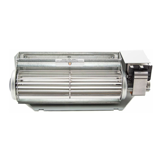
fireplace. This kit contains one blower, one speed control module, two
speed control module securing screws and these instructions.
INSTALLATION INSTRUCTIONS
Step 1. Turn off the fireplace and allow it to cool before proceeding.
Step 2. If the appliance is connected to 120 volt power, disconnect
the power.
Step 3. Shut off the gas supply to the fireplace.
Step 4. Open the lower compartment door (either a radiant panel or
louver assembly) by pushing in simultaneously the left and right side of
the door. (The door is hinged at the bottom.)
Step 5. D-400, D-500, D-600 and D-800 series; B-500, B-600, and
B-800 series; and MDT3328 and MDR3328 Fireplaces - Remove the
bottom panel or louver assembly by removing the screw at each end of
the panel or louver assembly, retain the end spacers, and then pull the
panel or the louver assembly from the unit.
Elite-2 Series Fireplaces - Remove the bottom compartment door (on
Multi-Open fireplaces, the modesty-panel-side door) by sliding the
hinge pin, located at the door's left side, to the right until it disengages
from the left corner post hole. Pull the door diagonally to the left, away
from the fireplace.
Step 6. Elite-2 Series Fireplaces - Remove the modesty panel as
follows: lift the modesty panel by the tab on the panel's right end, pull
the right end of the panel away from cabinet and then pull the panel
diagonally out of the corner post slots on the left side of the unit. Remove
the modesty panel carefully, so that none of the wires become loose or
disconnected.
Step 7. Front-open direct vent and B-vent units -
Slide the blower assembly through the front opening to the middle rear
area of the cabinet base. Position the blower assembly so that the tabs
(located on the cabinet base) are seated in the notches of the blower
bracket. Then bend the tabs over to secure the blower assembly. See
Figure 1, direct vent models; Figure 3, B-vent models .
750,029M REV. F 05/2005
FOR USE WITH GAS FIREPLACES
Figure 1
Figure 2
Figure 3
NOTE: DIAGRAMS & ILLUSTRATIONS NOT TO SCALE.
BLOWER
BLOWER MOUNTING TABS
CONTROL MODULE
MODESTY PANEL
BLOWER KIT INSTALLATION - ELITE FRONT-OPEN DIRECT VENT FIREPLACE
TOP VIEW
BLOWER MOUNTED
HERE ON MPD35ST
MOUNTING
MODEL
CONTROL
MODULE
MODESTY
PANEL
VIEW A
FIGURE 8
BLOWER KIT INSTALLATION FOR MULTI-OPEN DIRECT VENT FIREPLACE
(See-through, Peninsula, Corner left)
CAUTION:
ROUTE BLOWER ELECTRICAL CORDS, SO THAT THEY ARE POSITIONED
WELL AWAY FROM THE ROTATING BLOWER PARTS
BLOWER
BLOWER MOUNTING TABS
VIEW A
FIGURE 9
CONTROL MODULE
CONTROL MODULE MOUNTING TABS
BLOWER KIT INSTALLATION FOR B-VENT FRONT-OPEN FIREPLACE
TOP VIEW
HEARTH PRODUCTS
KITS AND ACCESSORIES
BLOWER KIT FBK-250
JUNCTION
BOX
ELECTRICAL
OUTLET
USE MODULE
VIEW A
HOLES 1 AND 2
FIGURE 8
(SEE FIGURE 8)
BLOWER
TABS
JUNCTION BOX
ELECTRICAL
OUTLET
USE MODULE
HOLES 1 AND 2
(SEE FIGURE 8)
JUNCTION
BOX
ELECTRICAL
OUTLET
1
Advertisement

Summary of Contents for Lennox Hearth Products FBK-250
- Page 1 GENERAL INFORMATION BLOWER JUNCTION This blower kit may be used with gas fireplaces. The FBK-250 blower kit is used when unit-mounted variable speed blower control is desired. The ELECTRICAL blower is installed beneath the firebox. Room air is drawn in through the...
- Page 2 BLOWER JUNCTION BLOWER MOUNTING TABS 12” MINIMUM FIELD PROVIDED ELECTRICAL EXTENSION CORD OUTLET CONTROL MODULE BLOWER MOUNTING TABS JUNCTION CONTROL MODULE ELECTRICAL MODESTY USE MODULE VIEW A OUTLET PANEL HOLES 1 AND 2 FIGURE 8 (SEE FIGURE 8) VIEW A BLOWER KIT INSTALLATION FOR MULTI-OPEN DIRECT VENT FIREPLACE FIGURE 8 (Corner Right)
- Page 3 Step 10. Direct vent units - Place the front lip of the control module Step 14. Elite-2 Series Gas Fireplaces - Reinstall the modesty panel. Reinstall the modesty panel carefully, so that none of the underneath the front flange of the cabinet bottom panel as shown in View A, Figure 8 .
- Page 4 Figure 10 NOTE: DIAGRAMS & ILLUSTRATIONS NOT TO SCALE. Lennox Hearth Products reserves the right to make changes at any time, without notice, in design, materials, specifications, prices and also to discontinue colors, styles and products. Consult your local distributor for fireplace code information.


Need help?
Do you have a question about the FBK-250 and is the answer not in the manual?
Questions and answers